US4531300A - Electronic inclination gauge with acceleration compensation - Google Patents
Electronic inclination gauge with acceleration compensation Download PDFInfo
- Publication number
- US4531300A US4531300A US06/607,997 US60799784A US4531300A US 4531300 A US4531300 A US 4531300A US 60799784 A US60799784 A US 60799784A US 4531300 A US4531300 A US 4531300A
- Authority
- US
- United States
- Prior art keywords
- signal
- output
- vehicle
- respect
- providing
- Prior art date
- Legal status (The legal status is an assumption and is not a legal conclusion. Google has not performed a legal analysis and makes no representation as to the accuracy of the status listed.)
- Expired - Fee Related
Links
Images


Classifications
-
- G—PHYSICS
- G01—MEASURING; TESTING
- G01C—MEASURING DISTANCES, LEVELS OR BEARINGS; SURVEYING; NAVIGATION; GYROSCOPIC INSTRUMENTS; PHOTOGRAMMETRY OR VIDEOGRAMMETRY
- G01C9/00—Measuring inclination, e.g. by clinometers, by levels
- G01C9/02—Details
- G01C9/08—Means for compensating acceleration forces due to movement of instrument
Definitions
- the invention pertains to the art of electrolytic accelerometers used as tilt sensors and, more particularly, to devices of this type which include means for providing compensation for acceleration errors when used in a moving vehicle.
- the invention relates to apparatus for sensing and measuring changes in inclination.
- Such apparatus has many applications; for example, in one form the apparatus may be used to sense or measure the variations in tilt of a surface from a datum position such as the horizontal.
- the invention may be used to measure accurately the grade of a road bed being traversed. Heavily loaded trucks may be unable to negotiate a road beyond a predetermined grade, and hence would find useful a device capable of measuring the grade while in motion and before stopping. Highway departments would find such a device useful for measuring the grades of highway under construction or for surveying roads about to be modernized.
- the present invention provides a gauge for compensating the acceleration sensitive response of a liquid level sensor gravity reference by utilizing an independent sensing of velocity and processing the value obtained to compensate the output of the sensor to yield a measurement of road grade free of acceleration effects.
- this approach eliminates mechanical gears and linkages and substantially reduces the cost, while providing improved effectiveness and accuracy.
- the present invention obviates the above-discussed disadvantages of the prior art instruments for measuring road bed inclination in a moving vehicle subject to an acceleration by providing a tilt-sensitive transducer having an output corresponding to the acceleration and to the angle and direction of the transducer along a reference axis with respect to a gravitational field.
- the apparatus includes a velocity sensor coupled to the vehicle to provide an output corresponding to a velocity component of the vehicle along the reference axis, and a circuit for processing the velocity signal to derive a signal corresponding to the component of acceleration along the reference axis.
- the acceleration signal is algebraically subtracted from the transducer output signal thereby nulling out the acceleration signal component and providing an output which is representative of the inclination of the reference axis with respect to the gravitational field, independent of the acceleration of the vehicle.
- the corrected output is then coupled to an output indicator for providing a reading indicative of the inclination of the vehicle and the road bed on which it travels.
- the tilt transducer comprises a liquid level potentiometer symmetrically excited by a bipolar signal source, which provides an output whose phase and amplitude corresponds to the inclination of the level with respect to the gravitational field.
- the bipolar output is then rectified and provides a unidirectional signal of variable amplitude and polarity corresponding to the tilt of the instrument.
- a speedometer in the vehicle is coupled to a sensor which provides an output signal responsive to the speed of the vehicle, which output signal is then differentiated to provide an acceleration component in the direction of travel. Since the tilt transducer is also sensitive to the acceleration of the vehicle, by subtracting the acceleration component derived from the speedometer from the transducer output signal a resultant output is provided which is independent of vehicular acceleration and depends only on the tilt of the sensor.
- FIG. 1 is a schematic view of a vehicle ascending a grade, showing the error introduced by longitudinal acceleration.
- FIG. 2 shows how the algebraic combination of the acceleration component due to gravity and the longitudinal component due to vehicular motion produces a resultant tilt error.
- FIG. 3 is a schematic block diagram showing the system of the present invention.
- FIG. 4A is a schematic circuit diagram of a transducer excitation circuit as used in the present invention.
- FIG. 4B is a schematic circuit diagram of a demodulation circuit as used in the present invention.
- FIG. 4C is a schematic diagram of a velocity sensor and integrator as used in the present invention.
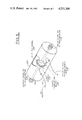
- FIG. 5 is a perspective view of a speedometer sensor for providing a velocity output signal.
- FIG. 6 is a conceptual view in perspective showing how the elements of the present invention are packaged for a vehicular installation.
- the improved system includes means for compensating for the error inducing acceleration components so that the tilt indicating instrument responds to an actual vertical gravitational acceleration rather than to an apparent vertical.
- the means provided herein for compensating for the acceleration error utilizes the motion of the vehicle to provide a velocity signal which is then processed to derive a longitudinal acceleration component.
- the acceleration component of the vehicle is algebraically subtracted from the acceleration component of the transducer thereby providing an output proportional only to the angular inclination of the road bed from the horizontal and independent of the vehicular acceleration in the direction of travel.
- FIG. 1 shows a vehicle 10 traveling along a road bed 12 inclined at a tilt angle ⁇ from the horizontal plane 18. It is desired to measure the tilt angle ⁇ of the road bed from instrumentation located within the vehicle 10. It may be seen that a gravity reference located within the vehicle will be subject to a total acceleration vector a T which is the vector sum of the earth's gravitational acceleration vector a G and the acceleration vector due to the fore and aft speed changes of the vehicle, a V . Since the tilt sensor measures total acceleration due to its inability to distinguish between the actual tilt of the vehicle as referenced to the gravitational vector a G , and the apparent tilt, it will display a pitch angle error by an amount equal to the angle ⁇ . As an example, it may be assumed the vehicle is traveling at 55 mph and reduces its speed to 45 mph over a ten second period. The resultant deceleration is:
- dV/dt represents the derivative of velocity
- ⁇ V/ ⁇ t represents the resultant acceleration when measured over a suitably short interval.
- the output of the gravity reference sensor is influenced by the accelerations thereon to a significant effect.
- the present invention provides for sensing the longitudinal component of acceleration and compensating for its effect so as to indicate the true grade of the road bed. This is accomplished by providing a tilt transducer comprised of a liquid level of the bubble type including a containing vial, electrodes, and a conductive fluid.
- the vial is preferably mounted within a housing which is aligned along a reference axis with respect to the gravitational field.
- the vial is excited by an a.c. source and contains an electrolyte providing a variable impedance with respect to exciting contacts disposed at opposing ends of the vial and a centrally disposed common contact.
- the transducer thereby acts as a potentiometer when excited by a balanced voltage source, to provide an output responsive in magnitude and phase to the direction and extent of inclination of the transducer, thereby providing an indication of the inclination of the reference axis with respect to the gravitational field.
- the output of the device is subject to the acceleration error previously described and must be corrected therefor.
- the a.c. output is rectified in a suitable demodulator providing a bipolar pulse output and integrated to provide a unidirectional or d.c. output with polarity that is variable in accordance with the inclination of the transducer.
- Acceleration correction is provided by a velocity signal which may be derived by coupling to a conventional speedometer on the vehicle, and processing the resultant velocity signal through a differentiating circuit, thereby providing an output voltage proportional to the acceleration of the vehicle.
- This output suitably scaled in d.c. form, may be subtracted from the integrated transducer output, thereby providing a resultant output indicative of the inclination of the reference axis and independent of the acceleration of the vehicle.
- a conventional astable multivibrator 20 is used to generate a square wave pulse train 22.
- the period of oscillation is primarily determined by the time constants of associated components, as is described below.
- the pulse output 22 is used to drive an amplifier 26 which is biased by a voltage regulator 24 to energize a signal bus 25 which is at a positive potential with respect to a power supply return 27. Since both the signal ground and a d.c. supply reference voltage developed by regulator 24 on line 29 are essentially independent of battery supply voltage, the resultant output 28 of amplifier 26 is a highly stable square wave which is substantially independent of supply voltage variations.
- the pulse output 28 of amplifier 26 is applied to an end electrode 34 of conventional liquid level sensor 36.
- the signal 28 is also applied to an inverter 30 which supplies a signal 32, 180° out-of-phase with signal 28, to electrode 38 which is disposed at the opposing end of sensor 36.
- the sensor output is provided from central electrode 40 and coupled to a phase demodulator 42.
- the invention is not limited to the use of electrolytic sensors, and any other type of deflection sensor of the potentiometric type is also suitable.
- the magnetically coupled pendulous accelerometer described in said U.S. Pat. No. 4,277,895 would be suitable.
- Other potentiometric sensors with resistive elements, whose resistances varies in magnitude and sense according to the extend and direction of tilt, may also be used.
- the a.c. source 26 is arranged to provide to sensor 36 two out-of-phase a.c. voltages of equal amplitude with respect to the common signal bus 25, the signal supplied by electrode 40 is dependent in amplitude and phase on the degree and direction of tilt of the sensor 36.
- the output 22 of oscillator 20 and the sensor output on line 44 are fed to the phase demodulator 42.
- the demodulator is phase synchronized to signal 22 from oscillator 20 and detects the amplitude of the sensor output from electrode 40 to provide a d.c. voltage, the magnitude of which is proportional to the angle of inclination from the reference and the sense (positive or negative) of which is dependent on the direction of inclination of the sensor 36.
- the output voltage of demodulator 42 is coupled to a buffer amplifier 46 and then to a potentiometer 48 for calibrating the sensor 36 to a known angular standard inclination.
- Amplifier 64 is used to couple the output of potentiometer 48 and an acceleration correction signal, in a manner to be described.
- a velocity sensor 50 is provided and may be mounted in a housing in the vehicle.
- the sensor is coupled to a speedometer or other element linked to the drive train of the vehicle and thus provides an output proportional to the speed of the vehicle to pulse generator 52.
- a suitable velocity sensor may be constructed by coupling a shutter to the speedometer shaft and using the shutter to interrupt a source of light impinging on a phototransistor.
- Pulse generator 52 is adapted to provide a square wave output of fixed pulse duration and pulse width, whose output frequency corresponds to the input frequency from velocity sensor 50. The output of pulse generator 52 is filtered, applied to amplifier 54, and then to capacitor 56.
- Capacitor 56 and resistor 58 in combination with amplifier 54 form a simple differentiator circuit which accepts the velocity input from pulse generator 52 and by differentiation provides a voltage proportional to the rate of change of speed or acceleration to inverter 60 as in equation (1). Additional circuitry, shown in FIG. 4C to be described, mateches the transient response of inverter 60 to the corresponding time constant of sensor 36. Thus, when sensor 36 is offset from a preset reference level, thereby providing a d.c.
- a corresponding acceleration output from inverter 60 is adjusted by means of potentiometer 62 and mixed with the detected sensor output from potentiometer 48 so that it will exactly cancel the acceleration forces sensed by electrolytic sensor 36, thus cancelling any acceleration outputs from sensor 36 and providing d.c. output at terminal 68 that reflects only the angular grade reading, independent of acceleration of the vehicle.
- Any suitable d.c. indicator may be used as an output device when calibrated to present a grade reading.
- this could be a digital voltmeter or an analog voltmeter, scaled to provide a useful range of angle readings, such as 0 to 10 degrees, plus or minus.
- the square wave oscillator 20 is supplied power from a single d.c. source which may be a twelve-volt vehicular battery.
- Oscillator 20 is comprised of an astable multivibrator such as a digital integrated circuit, type CD 4047.
- the period of the square wave produced at the output 70 is a function of the external components R 1 and C 1 .
- This circuit provides a 50% duty cycle with good frequency stability operable over a wide temperature range. A frequency of 500 H Z is suitable for this application but other frequencies may also be chosen.
- the circuit shown provides essentially a twelve volt peak output with respect to d.c. ground to the base of transistor amplifier 72, which drives amplifier circuit 26.
- Amplifier 72 may be a conventional transistor type amplifier such as type 2N2432.
- Amplifier 72 is coupled to oscillator 70 by resistor R 2 and biased from a precision voltage regulator 24 through resistor R 3 .
- Voltage regulator 24 is comprised of a reference zener diode 76 which is preferably temperature compensated and here selected to provide an output of 6.4 volts d.c.
- Resistor R 4 couples diode 76 to the 12 volt power supply.
- the d.c. return of diode 76 is applied to a bus 27 which constitutes the d.c. return or power ground.
- a voltage follower 80 which may be comprised of a conventional integrated circuit operational amplifier, such as type LM148, provides a low impedance 6.4 volt output which is applied to signal ground bus 25.
- Capacitor C 2 filters this supply in a conventional manner.
- the voltage regulator circuit 24 thus provides positive and negative supply voltages with respect to signal ground from a single 12-volt power supply.
- the +6.4 volt output from amplifier 80 is applied through voltage divider R 5 , R 6 in combination with series connected resistor R 8 to a negative (-) input of operational amplifier 84.
- This d.c. level is also coupled through voltage divider R 7 , R 9 to the positive (+) differential input.
- Resistor R 10 controls the gain of amplifier 84.
- Amplifier 84 has a gain adjusted to provide about +9 volts with respect to power ground 27, on line 74, which thereby provides a voltage reference of approximately 2.6 volts with respect to the signal ground 25.
- Amplifier 84 may be a conventional operational amplifier, such as type LM11.
- Amplifier circuit 26 is further comprised of a second stage operational amplifier 86, with one input driven by amplifier 72 through series resistor R 1 , and a second input connected to ground through resistor R 12 , in a conventional manner.
- Resistor R 13 is adjusted to provide a suitable gain factor so that the output of amplifier 86 appears as a square wave pulse of approximately 2.6 volts peak-to-peak across capacitor C 3 from where it is coupled to electrode 34 of transducer 36.
- the output of amplifier 86 is also coupled to inverter 88 through resistor 14 and is biased by resistors R 15 and R 16 to provide an output voltage across capacitor C 4 which is equal to amplitude but 180° degrees out of phase with the voltage across capacitor C 3 .
- Capacitor C 4 is coupled to electrode 38.
- electrodes 34 and 38 are biased by square wave signals of equal voltage but opposing polarity.
- Transistors 90 and 92 which may be type 2N2945 and 2N2432, respectively, are bipolar transistors of the p-n-p and n-p-n type, respectively. The transistors are connected in a grounded collector configuration, and operate in a saturated switching mode.
- the square wave reference line a from oscillator 20 is coupled through resistors R18 and R20, respectively, to the base of an associated transistor 90,92.
- the signal output from the transducer 36 is coupled through resistor R17 to the emitter of transistor 90, and through resistor R19 to the emitter of transistor 92.
- Resistor R21 and resistor R22 couple emitters of transistor 90 and transistor 92, respectively to the dual inputs of a differential amplifier 94.
- a feedback resistor R24 coupled across amplifier 94 determines the amplifier gain.
- the output of amplifier 94 is applied to filter R25, C5, R26.
- the output waveform of amplifier 94 is a pulse train of negative or positive polarity with respect to reference a, corresponding to the sense of the angle of inclination of transducer 36, and an amplitude corresponding to the deviation of the transducer from the reference axis.
- the pulse train is filtered by R25, C5, R26 and the d.c. voltage derived therefrom applied to current driver 46.
- the output of driver 46 represents a current or voltage corresponding to the direction and magnitude of the inclination of transducer 36 from the reference axis. This signal is then applied to potentiometer 48 to permit calibration against a standard of angular deviation.
- the calibration was established at 0.175 V/DEG, corresponding to 0.1 V/% Grade.
- the output of potentiometer 48 is coupled through resistor 27 to the input of operational amplifier 96 whose function is to combine the signal component representing angular displacement within an acceleration component whose derivation is described below.
- a feedback network C6, R28 is applied to amplifier 96 so as to control the gain and transient response to be compatible with the response of sensor 36.
- Circuit 50 comprises a velocity sensor for deriving a voltage proportional to the speed of the vehicle.
- a light source 100 which may be an LED, is coupled through limiting resistor R 30 to a suitable source of power.
- a light sensitive device such as a phototransistor 104 is mounted in proximity to the light source 100.
- a shutter 102 Interposed between the light source and the phototransistor is a shutter 102 which may be comprised of a circular plate having radially extending fins therefrom, for interrupting the light path.
- Shutter 102 is coupled to a drive shaft of the vehicle or the speedometer cable.
- Photodiode 104 is biased through resistor R31 from the vehicle power source so as to produce an output current when energized by light source 100.
- the output is applied to resistor R32 and coupled to amplifier 106 to provide a signal of variable pulsewidth and pulse repetition rate, responsive to the speed of the vehicle.
- Operational amplifier 106 is biased by resistors R33, R34 to provide an output pulse train to oscillator circuit 52 with an average value of approximately 1 V/DC that is never driven negative.
- Oscillator 108 is a monostable multivibrator which outputs a pulse of predetermined duration and amplitude and a repetition rate proportional to the velocity of the vehicle.
- Resistor R35 and capacitor C7 determine the pulsewidth and duration in a conventional manner.
- the output of oscillator 108 is filtered by network R36, R37, C8 and coupled to amplifier 110.
- Network R40, C9 determines the gain and transient response of amplifier 110 and provides additional filtering.
- the output of amplifier 110 is an analog voltage proportional to the speed of the vehicle. In the embodiment shown herein the circuit constants were chosen to provide approximately 0.175 V/MPH.
- the analog speed output is coupled through series connected resistor R41 and capacitor C10 to operational amplifier 112.
- Series capacitor C 10 and shunt resistor R42 in combination with amplifier 112 provide a differentiating function so that the input to resistor R43 represents a voltage proportional to the rate of change of speed, or acceleration.
- Amplifier 114 whose gain is controlled by resistors R44 and R45, inverts the signal applied from resistor R43.
- Capacitor C12 is used to adjust the time contant of response of amplifier 114 so that it matches the transient response of transducer 36. The purpose of this correction is to avoid under-correction or over-correction of the resultant acceleration voltage applied to the buffer amplifier 96.
- the output voltage from inverter 114 is applied to potentiometer R46. R46 is adjusted to calibrate the acceleration voltage applied to amplifier 96 on line c.
- the acceleration correction voltage is suitably polarized so that when combined with the angular voltage component at amplifier 96 it will provide a resultant voltage indicative of the sense and angular deviation of transducer 36 from a reference axis aligned with the vehicle. This output will be independent of the vehicular acceleration along the line of measurement.
- FIG. 5 shows a conceptual mechanical implementation of velocity sensor 50.
- a cylindrical housing 120 has a shaft 122 concentrically mounted therein on suitable support bearings, not shown.
- a first end 124 of the shaft is coupled to a transmission member which drives a speedometer cable.
- An output coupling 126 may be used to drive the speedometer when the sensor 50 is interposed between the existing speedometer and speedometer cable.
- Mounted on shaft 122 is a wheel 128 having a plurality of regular pheripheral slots 129.
- Mounted within the housing and illuminating the slotted wheel is a light source 130 powered by the vehicular battery through cable 136.
- a block 132 having mounted thereon a phototransistor.
- wheel 128 When shaft 122 is driven by the action of the moving vehicle, wheel 128 will periodically interrupt a beam of light from light source 130, thereby energizing phototransistor block 132 in a periodic manner.
- the resultant pulse output is provided to the external electronic circuit of FIG. 4C on cable 134 for processing and readout.
- a suitable system configuration is shown in FIG. 6.
- the speed sensor 141 is provided with a mechanical input from the drive shaft and in turn may be coupled to provide an output to drive the speedometer cable. Power for the system is furnished by the vehicular battery, although a dedicated supply is also suitable.
- a tilt transducer 140 is comprised of a suitable housing which may be mounted and aligned with the vehicle frame with respect to a predetermined reference axis. Transducer 140 has contained therein a suitable tilt transducer such as sensor 36, as shown in FIG. 4A.
- the sensor output signals are conveyed on a cable 142 to the enclosure 144, which contains the electronic circuitry of FIGS. 4A, 4B, and 4C, except for the circuitry associated with sensor 141.
- Velocity signals from speed sensor 141 are coupled to enclosure 144 by means of cable 146.
- Enclosure 144 also contains a suitable readout for providing a visual indication of the measured grade.
- the tilt transducer 36 which is responsive both to angular inclination and acceleration, is coupled to a source of pulses 26 and a source of phase inverted pulses 30 derived from a stabilized source of reference voltage 20.
- a differential voltage is developed across electrodes 34-40 and 38-40 of the transducer, due to the unequal areas of the electrodes in contact with the electrolyte, and an output signal at electrode 40 is derived from the transducer which represents by its polarity and amplitude the angle and direction of inclination of the transducer with respect to the reference axis.
- the resultant output is also responsive to a longitudinal acceleration of the vehicle.
- a phase demodulator 42 receives the output signal from the transducer and a reference signal 22 from the pulse source 20, which is rectified to provide a bipolar signal whose amplitude and phase are porportional to the angle and direction of inclination of the transducer.
- a sensor 141 mounted in a vehicle is coupled to a drive shaft or speedometer cable so as to provide a pulse signal output to amplifier 54 representative of the longitudinal velocity of the vehicle in which the apparatus is mounted.
- the velocity signal is differentiated at amplifier 54 to provide a signal representative of the longitudinal acceleration of the vehicle.
- the demodulated signal from the transducer 36 and the acceleration signal from amplifier 54 are algebraically combined after sutable buffering so as to cancel the acceleration component in the transducer signal output.
- the resultant output at terminal 68 is indicative of the inclination of the reference axis of the vehicle with respect to the gravitational field and free from any error induced by accelerations of the vehicle.
- Absolute readings may be obtained by suitable calibration of the acceleration and angular displacement components.
Landscapes
- Physics & Mathematics (AREA)
- Engineering & Computer Science (AREA)
- General Physics & Mathematics (AREA)
- Radar, Positioning & Navigation (AREA)
- Remote Sensing (AREA)
- Gyroscopes (AREA)
- Steroid Compounds (AREA)
- Oscillators With Electromechanical Resonators (AREA)
Abstract
Description
a=dV/dt=ΔV/Δt (1)
Claims (16)
Priority Applications (4)
| Application Number | Priority Date | Filing Date | Title |
|---|---|---|---|
| US06/607,997 US4531300A (en) | 1984-05-07 | 1984-05-07 | Electronic inclination gauge with acceleration compensation |
| JP60048084A JPS60238712A (en) | 1984-05-07 | 1985-03-11 | Electronic inclinometer having acceleration compensation function and compensating method thereof |
| IL74996A IL74996A0 (en) | 1984-05-07 | 1985-04-23 | Electronic inclination gauge |
| EP85303126A EP0161873A2 (en) | 1984-05-07 | 1985-05-02 | Electronic inclination gauge with acceleration compensation |
Applications Claiming Priority (1)
| Application Number | Priority Date | Filing Date | Title |
|---|---|---|---|
| US06/607,997 US4531300A (en) | 1984-05-07 | 1984-05-07 | Electronic inclination gauge with acceleration compensation |
Publications (1)
| Publication Number | Publication Date |
|---|---|
| US4531300A true US4531300A (en) | 1985-07-30 |
Family
ID=24434609
Family Applications (1)
| Application Number | Title | Priority Date | Filing Date |
|---|---|---|---|
| US06/607,997 Expired - Fee Related US4531300A (en) | 1984-05-07 | 1984-05-07 | Electronic inclination gauge with acceleration compensation |
Country Status (4)
| Country | Link |
|---|---|
| US (1) | US4531300A (en) |
| EP (1) | EP0161873A2 (en) |
| JP (1) | JPS60238712A (en) |
| IL (1) | IL74996A0 (en) |
Cited By (30)
| Publication number | Priority date | Publication date | Assignee | Title |
|---|---|---|---|---|
| US4628729A (en) * | 1984-07-16 | 1986-12-16 | U.S. Philips Corporation | Arrangement for determining the instantaneous angular position of a moving object |
| US4888540A (en) * | 1987-08-10 | 1989-12-19 | Allied-Signal Inc. | Electronic torquer interface and erection control circuit |
| US5029473A (en) * | 1988-05-10 | 1991-07-09 | Baverische Motoren Werke Ag | Acceleration sensor |
| US5265472A (en) * | 1989-07-26 | 1993-11-30 | Daimler-Benz Aktiengesellschaft | Process for compensating acceleration sensor errors |
| US5429442A (en) * | 1992-03-05 | 1995-07-04 | International Business Machines Corp. | Print hammer coil current control |
| US5428902A (en) * | 1994-02-24 | 1995-07-04 | Precision Navigation, Inc. | Inclinometer sensing circuitry and operation |
| US5524894A (en) * | 1994-11-23 | 1996-06-11 | Shannon; Allan P. | Head movement sensor for golf practice |
| EP0689116A3 (en) * | 1994-06-22 | 1997-10-08 | Gen Motors Corp | Method and apparatus for estimating incline and bank angles of a road surface |
| US5678527A (en) * | 1994-11-14 | 1997-10-21 | Yamaha Hatsudoki Kabushiki Kaisha | Induction and charge forming system for gaseous fueled engine |
| US5703484A (en) * | 1993-10-04 | 1997-12-30 | The Charles Machine Works, Inc. | Roll independent variable inductance inclinometer |
| WO1997049973A1 (en) * | 1996-06-24 | 1997-12-31 | Vladimir Mendelevich Olshansky | Inclinometer |
| US5774996A (en) * | 1995-02-14 | 1998-07-07 | Nissho Corporation | Biaxial inclination sensor |
| EP0903267A1 (en) * | 1997-08-21 | 1999-03-24 | Bayerische Motoren Werke Aktiengesellschaft, Patentabteilung AJ-3 | Apparatus and method for controlling the inflation of a restraint system in a vehicle |
| US5956664A (en) * | 1996-04-01 | 1999-09-21 | Cairo Systems, Inc. | Method and apparatus for monitoring railway defects |
| US5987979A (en) * | 1996-04-01 | 1999-11-23 | Cairo Systems, Inc. | Method and apparatus for detecting railtrack failures by comparing data from a plurality of railcars |
| WO2001085510A1 (en) * | 2000-05-02 | 2001-11-15 | Volvo Articulated Haulers Ab | Device and method for determining a highest allowable velocity of a vehicle |
| US20010048291A1 (en) * | 2000-03-09 | 2001-12-06 | Lautzenhiser John L. | Rate-of-change switches and controllable apparatus |
| US6349477B1 (en) | 1999-11-01 | 2002-02-26 | The Regents Of The University Of California | Self adjusting inclinometer |
| US6722199B2 (en) * | 1999-12-20 | 2004-04-20 | Heinz Ploechinger | Sensor for detecting a rotational movement or an angular acceleration |
| US20050021270A1 (en) * | 2003-07-22 | 2005-01-27 | Samsung Electronics Co., Ltd. | Method and apparatus for measuring speed of moving body using accelerometer |
| US20050139004A1 (en) * | 2003-12-26 | 2005-06-30 | Samsung Electronics Co., Ltd. | Method and apparatus for measuring speed of land vehicle using accelerometer |
| US20060027030A1 (en) * | 2004-08-09 | 2006-02-09 | Martin Schofl | Device and process for determining an acceleration-independent tilt angle |
| US20060293826A1 (en) * | 2005-05-13 | 2006-12-28 | Samsung Electronics Co., Ltd. | Apparatus and method for measuring speed of a moving object |
| US20070162251A1 (en) * | 2006-01-09 | 2007-07-12 | Stephen Todd | Device for measuring incline under acceleration |
| WO2012045556A1 (en) * | 2010-10-05 | 2012-04-12 | Zf Friedrichshafen Ag | Method for ascertaining an inclination of a vehicle in the direction of travel |
| US20130079949A1 (en) * | 2011-09-28 | 2013-03-28 | Caterpillar, Inc. | Inclination detection systems and methods |
| US20130080112A1 (en) * | 2011-09-28 | 2013-03-28 | Caterpillar Inc. | Inclination angle compensation systems and methods |
| DE102016225043A1 (en) * | 2016-12-14 | 2018-06-14 | Hahn-Schickard-Gesellschaft für angewandte Forschung e.V. | ACCELERATION COMPENSATED TILT SENSOR |
| US10559138B2 (en) | 2015-12-18 | 2020-02-11 | Ge Global Sourcing Llc | Sensor signal processing system and method |
| US11945705B2 (en) | 2018-09-13 | 2024-04-02 | Crown Equipment Corporation | System and method for controlling a maximum vehicle speed for an industrial vehicle based on a calculated load |
Families Citing this family (3)
| Publication number | Priority date | Publication date | Assignee | Title |
|---|---|---|---|---|
| ATE115717T1 (en) * | 1990-03-07 | 1994-12-15 | Hl Planartechnik Gmbh | ELECTRICAL MEASUREMENT ARRANGEMENT FOR MEASUREMENT RESPECTIVELY. CALCULATION OF THE LEVEL OR OTHER MECHANICAL DATA OF AN ELECTRICALLY CONDUCTIVE LIQUID. |
| JP3531452B2 (en) * | 1997-12-26 | 2004-05-31 | トヨタ自動車株式会社 | Vehicle slope determination device and vehicle height adjustment device |
| JP5899052B2 (en) * | 2012-06-04 | 2016-04-06 | パイオニア株式会社 | Inclination angle calculation device, inclination angle calculation method, inclination angle calculation program, and recording medium |
Citations (8)
| Publication number | Priority date | Publication date | Assignee | Title |
|---|---|---|---|---|
| US3277840A (en) * | 1965-02-26 | 1966-10-11 | Li Yao-Tzu | Vehicle stabilization system |
| US3871235A (en) * | 1969-06-27 | 1975-03-18 | Smiths Industries Ltd | Distance or speed measuring apparatus for land-vehicles |
| US3984918A (en) * | 1974-10-02 | 1976-10-12 | Sun Oil Company (Delaware) | Inclinometer |
| US4085375A (en) * | 1976-11-18 | 1978-04-18 | The Singer Company | Combined angular displacement measuring system and multiplier |
| DE2847128A1 (en) * | 1978-10-30 | 1980-05-14 | Tracto Technik | Axial position detector for percussion drill - indicates position w.r.t. horizontal using vibration-proofed reference level with electrical sensing and evaluation |
| US4246790A (en) * | 1979-10-22 | 1981-01-27 | General Motors Corporation | Combination speed transducer and speedometer cable |
| US4393709A (en) * | 1980-11-13 | 1983-07-19 | Alps Electric Co., Ltd. | Direction detection apparatus |
| JPS58131509A (en) * | 1982-01-29 | 1983-08-05 | Aisin Warner Ltd | Detector of inclination and acceleration |
-
1984
- 1984-05-07 US US06/607,997 patent/US4531300A/en not_active Expired - Fee Related
-
1985
- 1985-03-11 JP JP60048084A patent/JPS60238712A/en active Pending
- 1985-04-23 IL IL74996A patent/IL74996A0/en unknown
- 1985-05-02 EP EP85303126A patent/EP0161873A2/en not_active Withdrawn
Patent Citations (8)
| Publication number | Priority date | Publication date | Assignee | Title |
|---|---|---|---|---|
| US3277840A (en) * | 1965-02-26 | 1966-10-11 | Li Yao-Tzu | Vehicle stabilization system |
| US3871235A (en) * | 1969-06-27 | 1975-03-18 | Smiths Industries Ltd | Distance or speed measuring apparatus for land-vehicles |
| US3984918A (en) * | 1974-10-02 | 1976-10-12 | Sun Oil Company (Delaware) | Inclinometer |
| US4085375A (en) * | 1976-11-18 | 1978-04-18 | The Singer Company | Combined angular displacement measuring system and multiplier |
| DE2847128A1 (en) * | 1978-10-30 | 1980-05-14 | Tracto Technik | Axial position detector for percussion drill - indicates position w.r.t. horizontal using vibration-proofed reference level with electrical sensing and evaluation |
| US4246790A (en) * | 1979-10-22 | 1981-01-27 | General Motors Corporation | Combination speed transducer and speedometer cable |
| US4393709A (en) * | 1980-11-13 | 1983-07-19 | Alps Electric Co., Ltd. | Direction detection apparatus |
| JPS58131509A (en) * | 1982-01-29 | 1983-08-05 | Aisin Warner Ltd | Detector of inclination and acceleration |
Cited By (42)
| Publication number | Priority date | Publication date | Assignee | Title |
|---|---|---|---|---|
| US4628729A (en) * | 1984-07-16 | 1986-12-16 | U.S. Philips Corporation | Arrangement for determining the instantaneous angular position of a moving object |
| US4888540A (en) * | 1987-08-10 | 1989-12-19 | Allied-Signal Inc. | Electronic torquer interface and erection control circuit |
| US5029473A (en) * | 1988-05-10 | 1991-07-09 | Baverische Motoren Werke Ag | Acceleration sensor |
| US5265472A (en) * | 1989-07-26 | 1993-11-30 | Daimler-Benz Aktiengesellschaft | Process for compensating acceleration sensor errors |
| US5429442A (en) * | 1992-03-05 | 1995-07-04 | International Business Machines Corp. | Print hammer coil current control |
| US5703484A (en) * | 1993-10-04 | 1997-12-30 | The Charles Machine Works, Inc. | Roll independent variable inductance inclinometer |
| US5428902A (en) * | 1994-02-24 | 1995-07-04 | Precision Navigation, Inc. | Inclinometer sensing circuitry and operation |
| EP0689116A3 (en) * | 1994-06-22 | 1997-10-08 | Gen Motors Corp | Method and apparatus for estimating incline and bank angles of a road surface |
| US5678527A (en) * | 1994-11-14 | 1997-10-21 | Yamaha Hatsudoki Kabushiki Kaisha | Induction and charge forming system for gaseous fueled engine |
| US5524894A (en) * | 1994-11-23 | 1996-06-11 | Shannon; Allan P. | Head movement sensor for golf practice |
| US5774996A (en) * | 1995-02-14 | 1998-07-07 | Nissho Corporation | Biaxial inclination sensor |
| US5956664A (en) * | 1996-04-01 | 1999-09-21 | Cairo Systems, Inc. | Method and apparatus for monitoring railway defects |
| US5987979A (en) * | 1996-04-01 | 1999-11-23 | Cairo Systems, Inc. | Method and apparatus for detecting railtrack failures by comparing data from a plurality of railcars |
| US6044698A (en) * | 1996-04-01 | 2000-04-04 | Cairo Systems, Inc. | Method and apparatus including accelerometer and tilt sensor for detecting railway anomalies |
| WO1997049973A1 (en) * | 1996-06-24 | 1997-12-31 | Vladimir Mendelevich Olshansky | Inclinometer |
| EP0903267A1 (en) * | 1997-08-21 | 1999-03-24 | Bayerische Motoren Werke Aktiengesellschaft, Patentabteilung AJ-3 | Apparatus and method for controlling the inflation of a restraint system in a vehicle |
| US6169946B1 (en) | 1997-08-21 | 2001-01-02 | Bayerische Motoren Werke Aktiengesellschaft | Device and method for controlling accident protection triggering devices in motor vehicles |
| US6349477B1 (en) | 1999-11-01 | 2002-02-26 | The Regents Of The University Of California | Self adjusting inclinometer |
| US6722199B2 (en) * | 1999-12-20 | 2004-04-20 | Heinz Ploechinger | Sensor for detecting a rotational movement or an angular acceleration |
| US8502641B2 (en) * | 2000-03-09 | 2013-08-06 | Intelpro Llc | Rate-of-change switches and controllable apparatus |
| US20010048291A1 (en) * | 2000-03-09 | 2001-12-06 | Lautzenhiser John L. | Rate-of-change switches and controllable apparatus |
| WO2001085510A1 (en) * | 2000-05-02 | 2001-11-15 | Volvo Articulated Haulers Ab | Device and method for determining a highest allowable velocity of a vehicle |
| US7120532B2 (en) | 2000-05-02 | 2006-10-10 | Volvo Articulated Haulers Ab | Device and method for determining a highest allowed velocity of a vehicle |
| US20050021270A1 (en) * | 2003-07-22 | 2005-01-27 | Samsung Electronics Co., Ltd. | Method and apparatus for measuring speed of moving body using accelerometer |
| US6928382B2 (en) * | 2003-07-22 | 2005-08-09 | Samsung Electronics Co., Ltd. | Method and apparatus for measuring speed of moving body using accelerometer |
| US20050139004A1 (en) * | 2003-12-26 | 2005-06-30 | Samsung Electronics Co., Ltd. | Method and apparatus for measuring speed of land vehicle using accelerometer |
| US7032450B2 (en) * | 2003-12-26 | 2006-04-25 | Samsung Electronics Co., Ltd. | Method and apparatus for measuring speed of land vehicle using accelerometer |
| US20060027030A1 (en) * | 2004-08-09 | 2006-02-09 | Martin Schofl | Device and process for determining an acceleration-independent tilt angle |
| EP1626248A1 (en) * | 2004-08-09 | 2006-02-15 | Bomag Gmbh | Device and method for determining an acceleration independent inclination angle |
| US20060293826A1 (en) * | 2005-05-13 | 2006-12-28 | Samsung Electronics Co., Ltd. | Apparatus and method for measuring speed of a moving object |
| US7289898B2 (en) * | 2005-05-13 | 2007-10-30 | Samsung Electronics Co., Ltd. | Apparatus and method for measuring speed of a moving object |
| US20070162251A1 (en) * | 2006-01-09 | 2007-07-12 | Stephen Todd | Device for measuring incline under acceleration |
| US7873458B2 (en) | 2006-01-09 | 2011-01-18 | Stephen Todd | Device for measuring incline under acceleration |
| WO2012045556A1 (en) * | 2010-10-05 | 2012-04-12 | Zf Friedrichshafen Ag | Method for ascertaining an inclination of a vehicle in the direction of travel |
| US20130079949A1 (en) * | 2011-09-28 | 2013-03-28 | Caterpillar, Inc. | Inclination detection systems and methods |
| US20130080112A1 (en) * | 2011-09-28 | 2013-03-28 | Caterpillar Inc. | Inclination angle compensation systems and methods |
| US9020776B2 (en) * | 2011-09-28 | 2015-04-28 | Caterpillar Inc. | Inclination angle compensation systems and methods |
| US9145144B2 (en) * | 2011-09-28 | 2015-09-29 | Caterpillar Inc. | Inclination detection systems and methods |
| AU2012209016B2 (en) * | 2011-09-28 | 2016-10-06 | Caterpillar Inc. | Inclination detection systems and methods |
| US10559138B2 (en) | 2015-12-18 | 2020-02-11 | Ge Global Sourcing Llc | Sensor signal processing system and method |
| DE102016225043A1 (en) * | 2016-12-14 | 2018-06-14 | Hahn-Schickard-Gesellschaft für angewandte Forschung e.V. | ACCELERATION COMPENSATED TILT SENSOR |
| US11945705B2 (en) | 2018-09-13 | 2024-04-02 | Crown Equipment Corporation | System and method for controlling a maximum vehicle speed for an industrial vehicle based on a calculated load |
Also Published As
| Publication number | Publication date |
|---|---|
| IL74996A0 (en) | 1985-08-30 |
| JPS60238712A (en) | 1985-11-27 |
| EP0161873A2 (en) | 1985-11-21 |
Similar Documents
| Publication | Publication Date | Title |
|---|---|---|
| US4531300A (en) | Electronic inclination gauge with acceleration compensation | |
| US5440923A (en) | Drivable slope-sensitive unit for measuring curvature and crossfall of ground surfaces | |
| US2362616A (en) | Pendulum compensator | |
| US4788773A (en) | Apparatus for measuring lateral inclination of a roadway with error compensation | |
| EP0123460A2 (en) | Precision inclinometer | |
| US4725957A (en) | Process for correcting angle errors in an electronic compass in vehicles | |
| EP0427882B1 (en) | Apparatus for measuring small displacements | |
| EP0228180A1 (en) | Systems to display saw blade angle and height | |
| GB2227315A (en) | Vehicle land navigating device | |
| US6204499B1 (en) | Method and apparatus for a rotation angle sensor | |
| FI930819A0 (en) | SYSTEM FOER CONTROL AV ETT JAERNVAEGSFORDONS ROTATION KRING DENNES LAENGDAXEL | |
| EP0806632B1 (en) | Vehicle navigation system with automatic calibration of on-board sensors | |
| EP0744622B1 (en) | Acceleration sensor | |
| US2659985A (en) | Method of and apparatus for pendulum compensating | |
| JPS63117211A (en) | Clinometer | |
| US2524934A (en) | Elevation recording apparatus | |
| CA1258765A (en) | Apparatus for measuring the lateral inclination of a supporting surface by means of a vehicle drivable thereon | |
| GB2090662A (en) | Navigational equipment for a vehicle | |
| SU478186A1 (en) | Device for recording the trajectory of the ground vehicle | |
| RU1797690C (en) | Gyrocompass | |
| RU2066283C1 (en) | Device for measuring rail track curvature radius | |
| SU1002548A1 (en) | Zenith angle converter | |
| SU678287A1 (en) | Inclination meter | |
| SU987531A1 (en) | Molecular electronic angle acceleration meter | |
| JPS6252409A (en) | Clinometer mounted on vehicle |
Legal Events
| Date | Code | Title | Description |
|---|---|---|---|
| AS | Assignment |
Owner name: SPERRY CORPORATION, GREAT NECK, NY 11020 A DE CORP Free format text: ASSIGNMENT OF ASSIGNORS INTEREST.;ASSIGNORS:HEIDEL, JEFFREY C.;SWARTZ, HAROLD L.;REEL/FRAME:004296/0621 Effective date: 19840507 |
|
| AS | Assignment |
Owner name: SCHAEVITZ SENSING SYSTEMS, INC., A DE. CORP. AND W Free format text: ASSIGNMENT OF ASSIGNORS INTEREST.;ASSIGNOR:HONEYWELL INC.,;REEL/FRAME:004736/0113 Effective date: 19870512 |
|
| AS | Assignment |
Owner name: SCHAEVITZ SENSING SYSTEM, INC., U.S. ROUTE 130 UNI Free format text: ASSIGNMENT OF ASSIGNORS INTEREST.;ASSIGNOR:HONEYWELL INC.,;REEL/FRAME:004753/0673 Effective date: 19870720 |
|
| AS | Assignment |
Owner name: SP-COMMERCIAL FLIGHT, INC., ONE BURROUGHS PLACE, D Free format text: ASSIGNMENT OF ASSIGNORS INTEREST.;ASSIGNORS:SPERRY CORPORATION;SPERRY RAND CORPORATION;SPERRY HOLDING COMPANY, INC.;REEL/FRAME:004838/0329 Effective date: 19861112 Owner name: SP-COMMERCIAL FLIGHT, INC., A DE CORP.,MICHIGAN Free format text: ASSIGNMENT OF ASSIGNORS INTEREST;ASSIGNORS:SPERRY CORPORATION;SPERRY RAND CORPORATION;SPERRY HOLDING COMPANY, INC.;REEL/FRAME:004838/0329 Effective date: 19861112 |
|
| AS | Assignment |
Owner name: HONEYWELL INC. Free format text: ASSIGNMENT OF ASSIGNORS INTEREST. EFFECTIVE DEC 30, 1986;ASSIGNOR:UNISYS CORPORATION;REEL/FRAME:004869/0796 Effective date: 19880506 Owner name: HONEYWELL INC.,MINNESOTA Free format text: ASSIGNMENT OF ASSIGNORS INTEREST;ASSIGNOR:UNISYS CORPORATION;REEL/FRAME:004869/0796 Effective date: 19880506 |
|
| FPAY | Fee payment |
Year of fee payment: 4 |
|
| FPAY | Fee payment |
Year of fee payment: 8 |
|
| REMI | Maintenance fee reminder mailed | ||
| LAPS | Lapse for failure to pay maintenance fees | ||
| FP | Lapsed due to failure to pay maintenance fee |
Effective date: 19970730 |
|
| STCH | Information on status: patent discontinuation |
Free format text: PATENT EXPIRED DUE TO NONPAYMENT OF MAINTENANCE FEES UNDER 37 CFR 1.362 |