US4530561A - Edge connector - Google Patents
Edge connector Download PDFInfo
- Publication number
- US4530561A US4530561A US06/394,221 US39422182A US4530561A US 4530561 A US4530561 A US 4530561A US 39422182 A US39422182 A US 39422182A US 4530561 A US4530561 A US 4530561A
- Authority
- US
- United States
- Prior art keywords
- feet
- body section
- projections
- electrical connector
- lips
- Prior art date
- Legal status (The legal status is an assumption and is not a legal conclusion. Google has not performed a legal analysis and makes no representation as to the accuracy of the status listed.)
- Expired - Fee Related
Links
Images


Classifications
-
- H—ELECTRICITY
- H01—ELECTRIC ELEMENTS
- H01R—ELECTRICALLY-CONDUCTIVE CONNECTIONS; STRUCTURAL ASSOCIATIONS OF A PLURALITY OF MUTUALLY-INSULATED ELECTRICAL CONNECTING ELEMENTS; COUPLING DEVICES; CURRENT COLLECTORS
- H01R13/00—Details of coupling devices of the kinds covered by groups H01R12/70 or H01R24/00 - H01R33/00
- H01R13/46—Bases; Cases
- H01R13/514—Bases; Cases composed as a modular blocks or assembly, i.e. composed of co-operating parts provided with contact members or holding contact members between them
-
- H—ELECTRICITY
- H01—ELECTRIC ELEMENTS
- H01R—ELECTRICALLY-CONDUCTIVE CONNECTIONS; STRUCTURAL ASSOCIATIONS OF A PLURALITY OF MUTUALLY-INSULATED ELECTRICAL CONNECTING ELEMENTS; COUPLING DEVICES; CURRENT COLLECTORS
- H01R12/00—Structural associations of a plurality of mutually-insulated electrical connecting elements, specially adapted for printed circuits, e.g. printed circuit boards [PCB], flat or ribbon cables, or like generally planar structures, e.g. terminal strips, terminal blocks; Coupling devices specially adapted for printed circuits, flat or ribbon cables, or like generally planar structures; Terminals specially adapted for contact with, or insertion into, printed circuits, flat or ribbon cables, or like generally planar structures
- H01R12/70—Coupling devices
- H01R12/7005—Guiding, mounting, polarizing or locking means; Extractors
- H01R12/7011—Locking or fixing a connector to a PCB
- H01R12/7047—Locking or fixing a connector to a PCB with a fastener through a screw hole in the coupling device
-
- H—ELECTRICITY
- H01—ELECTRIC ELEMENTS
- H01R—ELECTRICALLY-CONDUCTIVE CONNECTIONS; STRUCTURAL ASSOCIATIONS OF A PLURALITY OF MUTUALLY-INSULATED ELECTRICAL CONNECTING ELEMENTS; COUPLING DEVICES; CURRENT COLLECTORS
- H01R13/00—Details of coupling devices of the kinds covered by groups H01R12/70 or H01R24/00 - H01R33/00
- H01R13/46—Bases; Cases
- H01R13/502—Bases; Cases composed of different pieces
- H01R13/506—Bases; Cases composed of different pieces assembled by snap action of the parts
-
- H—ELECTRICITY
- H01—ELECTRIC ELEMENTS
- H01R—ELECTRICALLY-CONDUCTIVE CONNECTIONS; STRUCTURAL ASSOCIATIONS OF A PLURALITY OF MUTUALLY-INSULATED ELECTRICAL CONNECTING ELEMENTS; COUPLING DEVICES; CURRENT COLLECTORS
- H01R4/00—Electrically-conductive connections between two or more conductive members in direct contact, i.e. touching one another; Means for effecting or maintaining such contact; Electrically-conductive connections having two or more spaced connecting locations for conductors and using contact members penetrating insulation
- H01R4/02—Soldered or welded connections
Definitions
- the present invention relates to connectors for printed circuits and the like.
- it relates to connectors formed individually by the assembly of blocks of insulating material and contacts into such assemblies which may readily be shortened, either before or after completion of their assembly, to eliminate undesired lengths of connectors and provide a desired number of contacts only.
- Australian Patent No. 503,549 describes an electrical connector having five parts; the metal contacts, the body, a slide element made from insulating material which holds the contact elements in the body and two end feet which have teeth which mate into the contact cavities and lock the slide securely into the body of the connector.
- German Patent No. 1,936,0119 Another prior art connector is shown in German Patent No. 1,936,019.
- this suffers from the same disadvantage as the connector of the beforementioned Australian Patent, in that the tolerances of the components must be very exact to ensure adequate connection and as a result is prone to the end foot slipping loose.
- Another disadvantage is that the connector of the German Patent would not satisfy the height limitations required for standard connectors.
- the present invention therefore provides an electrical connector comprising:
- feet means having top and bottom projections with re-entrant lips so as to lock the feet means securely onto the supportive body without interferring with the contact elements in the said rows.
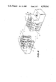
- FIG. 1 is an exploded perspective view of a connector according to a preferred embodiment of the present invention
- FIG. 2 is a perspective view of the assembled connector of the FIG. 1;
- FIGS. 3 and 4 are respectively plan and bottom plan views of the connector of FIG. 2.
- the body section 1 as can be seen in FIGS. 1 to 3 comprises a series of contact recesses 3.
- the contacts can be affixed by any suitable means into these recesses 3, such as by clipping over the shoulders 4 or clipping into the openings 5 which extend into the recesses 3 or by a forced fit between adajacent walls 6 and 6' of the recesses 3.
- the body section 1 also has a groove 7 running along the two lateral sides 8. This groove is not necessary for the workability of this claim and is provided as an additional means of support for other types of end feet. There is also a third groove 9 running along the base 10 of the body.
- the foot member 2 has two projections 11 with entrant lips 12, located adjacent the top of the feet members.
- the two projections 11 fit into the channels 15 with the lips 12 locking behind the shoulder 16 in the contact recess (see FIGS. 2 and 3).
- the projection 13 extends along the groove 9 with the lip extending into the second contact recess 3' (see FIG. 4).
- Two further projections 17 maybe located on the foot 2 to fit into the lateral grooves 7 of the body portion 1, (as shown in FIG. 2).
- the feet members are securely attached to the body member. Because of the type of attachment the tolerances for manufacture of the feet and the body are not as critical as those of the prior art connectors.
- the projections 11 and 13 are so shaped that they extend across the contact recesses 3 without interfering with the contacts fitted into the contact recesses (see FIGS. 3 and 4).
- the three types of projections rigidly affix the foot member to the body ameliorating any lateral or transverse movement between the foot member and the body.
- the feet members are removed and the contacts can be removed and the body shortened and the feet members reattached without any damage to the remaining contacts.
Landscapes
- Coupling Device And Connection With Printed Circuit (AREA)
- Connector Housings Or Holding Contact Members (AREA)
- Details Of Connecting Devices For Male And Female Coupling (AREA)
Applications Claiming Priority (2)
| Application Number | Priority Date | Filing Date | Title |
|---|---|---|---|
| AUPE9647 | 1981-07-08 | ||
| AU964781 | 1981-07-08 |
Publications (1)
| Publication Number | Publication Date |
|---|---|
| US4530561A true US4530561A (en) | 1985-07-23 |
Family
ID=3700415
Family Applications (1)
| Application Number | Title | Priority Date | Filing Date |
|---|---|---|---|
| US06/394,221 Expired - Fee Related US4530561A (en) | 1981-07-08 | 1982-07-01 | Edge connector |
Country Status (6)
| Country | Link |
|---|---|
| US (1) | US4530561A (enExample) |
| JP (1) | JPS5823180A (enExample) |
| AU (1) | AU8553682A (enExample) |
| DE (1) | DE3224954A1 (enExample) |
| FR (1) | FR2509538A1 (enExample) |
| GB (1) | GB2103891B (enExample) |
Cited By (13)
| Publication number | Priority date | Publication date | Assignee | Title |
|---|---|---|---|---|
| US5013263A (en) * | 1985-11-22 | 1991-05-07 | William Gordon | Modular electrical connector structure |
| US5038050A (en) * | 1989-10-31 | 1991-08-06 | Yazaki Eds | Junction relay box |
| US5129831A (en) * | 1991-07-26 | 1992-07-14 | Amp Incorporated | Right angle header shroud to board polarization and keying system |
| US5147226A (en) * | 1991-01-25 | 1992-09-15 | Amp Incorporated | Connector assembly and keyed alignment assist shroud therefor |
| US5147225A (en) * | 1991-01-25 | 1992-09-15 | Amp Incorporated | Shroud-to-board polarization and keying system |
| US5161996A (en) * | 1991-07-26 | 1992-11-10 | Amp Incorporated | Header assembly and alignment assist shroud therefor |
| EP0747998A2 (en) * | 1995-06-07 | 1996-12-11 | SAMTEC, Inc. | Connector having press fit mating shrouds |
| RU2138890C1 (ru) * | 1998-03-11 | 1999-09-27 | Акционерное общество открытого типа "Ракетно-космическая корпорация "Энергия" им.С.П.Королева" | Электросоединитель пакетный |
| US6464537B1 (en) | 1999-12-29 | 2002-10-15 | Berg Technology, Inc. | High speed card edge connectors |
| US20040203281A1 (en) * | 1997-08-14 | 2004-10-14 | The Panda Project, Inc. | Electrical connector having staggered hold-down tabs |
| US20110012597A1 (en) * | 2008-02-29 | 2011-01-20 | Koninklijke Philips Electronics N.V. | Fastener-less edge launch connector for mr-compatible medical monitoring |
| US20110151705A1 (en) * | 2009-12-21 | 2011-06-23 | Koichi Kagotani | Connector guide member and electrical connector device having the same |
| CN102570137A (zh) * | 2010-11-24 | 2012-07-11 | Wago管理有限责任公司 | 用于电气接线盒设备的支撑装置 |
Families Citing this family (4)
| Publication number | Priority date | Publication date | Assignee | Title |
|---|---|---|---|---|
| DE9410919U1 (de) * | 1994-07-07 | 1994-11-10 | Weidmüller Interface GmbH & Co, 32760 Detmold | Mehrpolige Anschlußklemmen-Stiftleiste für Leiterplatten |
| DE19520416C2 (de) * | 1995-06-02 | 1997-04-03 | Siemens Ag | Steckfassung |
| DE19836154C2 (de) * | 1998-08-10 | 2000-07-20 | Felten & Guilleaume Kabelwerk | Sockel für elektrische Kontakte |
| JP5585838B2 (ja) * | 2010-12-06 | 2014-09-10 | 第一精工株式会社 | コネクタ装置及びその製造方法 |
Citations (4)
| Publication number | Priority date | Publication date | Assignee | Title |
|---|---|---|---|---|
| US3172718A (en) * | 1963-03-20 | 1965-03-09 | Electronic Fittings Corp | Multiple contact receptacle for printed circuit boards and the like |
| US3601770A (en) * | 1969-07-17 | 1971-08-24 | United Carr Inc | Edge connector for printed circuit panels |
| US3822916A (en) * | 1972-11-16 | 1974-07-09 | Akzona Inc | In-situ extraction of mineral values from ore deposits |
| US3951494A (en) * | 1974-11-14 | 1976-04-20 | Molex Incorporated | Electrical connector |
-
1981
- 1981-07-08 AU AU85536/82A patent/AU8553682A/en not_active Abandoned
-
1982
- 1982-07-01 US US06/394,221 patent/US4530561A/en not_active Expired - Fee Related
- 1982-07-03 DE DE19823224954 patent/DE3224954A1/de not_active Withdrawn
- 1982-07-05 GB GB08219417A patent/GB2103891B/en not_active Expired
- 1982-07-07 JP JP57118326A patent/JPS5823180A/ja active Pending
- 1982-07-08 FR FR8211975A patent/FR2509538A1/fr active Granted
Patent Citations (4)
| Publication number | Priority date | Publication date | Assignee | Title |
|---|---|---|---|---|
| US3172718A (en) * | 1963-03-20 | 1965-03-09 | Electronic Fittings Corp | Multiple contact receptacle for printed circuit boards and the like |
| US3601770A (en) * | 1969-07-17 | 1971-08-24 | United Carr Inc | Edge connector for printed circuit panels |
| US3822916A (en) * | 1972-11-16 | 1974-07-09 | Akzona Inc | In-situ extraction of mineral values from ore deposits |
| US3951494A (en) * | 1974-11-14 | 1976-04-20 | Molex Incorporated | Electrical connector |
Cited By (20)
| Publication number | Priority date | Publication date | Assignee | Title |
|---|---|---|---|---|
| US5013263A (en) * | 1985-11-22 | 1991-05-07 | William Gordon | Modular electrical connector structure |
| US5038050A (en) * | 1989-10-31 | 1991-08-06 | Yazaki Eds | Junction relay box |
| US5147226A (en) * | 1991-01-25 | 1992-09-15 | Amp Incorporated | Connector assembly and keyed alignment assist shroud therefor |
| US5147225A (en) * | 1991-01-25 | 1992-09-15 | Amp Incorporated | Shroud-to-board polarization and keying system |
| US5129831A (en) * | 1991-07-26 | 1992-07-14 | Amp Incorporated | Right angle header shroud to board polarization and keying system |
| US5161996A (en) * | 1991-07-26 | 1992-11-10 | Amp Incorporated | Header assembly and alignment assist shroud therefor |
| EP0747998A2 (en) * | 1995-06-07 | 1996-12-11 | SAMTEC, Inc. | Connector having press fit mating shrouds |
| US20040203281A1 (en) * | 1997-08-14 | 2004-10-14 | The Panda Project, Inc. | Electrical connector having staggered hold-down tabs |
| RU2138890C1 (ru) * | 1998-03-11 | 1999-09-27 | Акционерное общество открытого типа "Ракетно-космическая корпорация "Энергия" им.С.П.Королева" | Электросоединитель пакетный |
| US6464537B1 (en) | 1999-12-29 | 2002-10-15 | Berg Technology, Inc. | High speed card edge connectors |
| US6561850B2 (en) | 1999-12-29 | 2003-05-13 | Berg Technology, Inc. | High speed card edge connectors |
| US20110012597A1 (en) * | 2008-02-29 | 2011-01-20 | Koninklijke Philips Electronics N.V. | Fastener-less edge launch connector for mr-compatible medical monitoring |
| US8564291B2 (en) | 2008-02-29 | 2013-10-22 | Koninklijke Philips N.V. | Fastener-less edge launch connector for MR-compatible medical monitoring |
| RU2501521C2 (ru) * | 2008-02-29 | 2013-12-20 | Конинклейке Филипс Электроникс, Н.В. | Краевой соединитель без крепежных элементов для медицинского контроля, совместимого с магнитно-резонансным оборудованием |
| US20110151705A1 (en) * | 2009-12-21 | 2011-06-23 | Koichi Kagotani | Connector guide member and electrical connector device having the same |
| US8425250B2 (en) * | 2009-12-21 | 2013-04-23 | Hirose Electric Co., Ltd. | Connector guide member and electrical connector device having the same |
| US8608503B2 (en) | 2009-12-21 | 2013-12-17 | Hirose Electric Co., Ltd. | Connector guide member and electrical connector device having the same |
| US8801454B2 (en) | 2009-12-21 | 2014-08-12 | Hirose Electric Co., Ltd. | Connector guide member and electrical connector device having the same |
| CN102570137A (zh) * | 2010-11-24 | 2012-07-11 | Wago管理有限责任公司 | 用于电气接线盒设备的支撑装置 |
| CN102570137B (zh) * | 2010-11-24 | 2016-05-04 | Wago管理有限责任公司 | 用于电气接线盒设备的支撑装置 |
Also Published As
| Publication number | Publication date |
|---|---|
| GB2103891B (en) | 1985-05-30 |
| DE3224954A1 (de) | 1983-02-10 |
| GB2103891A (en) | 1983-02-23 |
| JPS5823180A (ja) | 1983-02-10 |
| FR2509538B3 (enExample) | 1984-07-27 |
| AU8553682A (en) | 1983-01-13 |
| FR2509538A1 (fr) | 1983-01-14 |
Similar Documents
| Publication | Publication Date | Title |
|---|---|---|
| US4530561A (en) | Edge connector | |
| US4552423A (en) | Shunted electrical connectors | |
| US3775733A (en) | Terminal block and terminal connector | |
| EP1269578B1 (en) | Connector assembly with stabilized modules | |
| EP0482669B1 (en) | Electrical connector and method of making an electrical connector | |
| KR0182790B1 (ko) | 코딩 요소가 있는 접속기 조립체 | |
| US6890214B2 (en) | Multi-sequenced contacts from single lead frame | |
| US4758182A (en) | Electric connector | |
| JPH0350630Y2 (enExample) | ||
| US5037334A (en) | Connector with equal lateral force contact spacer plate | |
| EP0448382B1 (en) | Improved female terminal for an electrical connector | |
| GB2104735A (en) | Electrical connector | |
| GB2175152A (en) | Surface-mounted edge connector for p c b | |
| US4080041A (en) | Electrical connector | |
| US6394841B1 (en) | Electric connector having shield plates | |
| GB1590423A (en) | Electrical connector | |
| JPS60748B2 (ja) | 電気接続子ハウジング | |
| US3963296A (en) | Locking bar assembly for high voltage terminal blocks | |
| US4607906A (en) | Panel-mounted duplex electrical receptacle and power terminal strip | |
| US5006080A (en) | Electrical connector | |
| KR960016024A (ko) | 표면실장형 컨넥터 및 그 전기 콘택트 | |
| US4969825A (en) | Electrical connector | |
| EP0639873A2 (en) | Connector | |
| US3982809A (en) | Cord adapter | |
| US5370557A (en) | Keying system for low profile connector |
Legal Events
| Date | Code | Title | Description |
|---|---|---|---|
| AS | Assignment |
Owner name: AMTRON TYREE PTY. LIMITED 176 COPE STREET WATERLOO Free format text: ASSIGNMENT OF ASSIGNORS INTEREST.;ASSIGNORS:TYREE, CHRISTOPHER W.;POLAND, JOHN M.;REEL/FRAME:004327/0962 Effective date: 19840823 |
|
| REMI | Maintenance fee reminder mailed | ||
| LAPS | Lapse for failure to pay maintenance fees | ||
| STCH | Information on status: patent discontinuation |
Free format text: PATENT EXPIRED DUE TO NONPAYMENT OF MAINTENANCE FEES UNDER 37 CFR 1.362 |
|
| FP | Lapsed due to failure to pay maintenance fee |
Effective date: 19890723 |