US4530226A - Sweep-forming apparatus - Google Patents

Sweep-forming apparatus Download PDF

Info

Publication number
US4530226A
US4530226A US06/503,405 US50340583A US4530226A US 4530226 A US4530226 A US 4530226A US 50340583 A US50340583 A US 50340583A US 4530226 A US4530226 A US 4530226A
Authority
US
United States
Prior art keywords
forming
driving means
article
sweep
pinch roll
Prior art date
Legal status (The legal status is an assumption and is not a legal conclusion. Google has not performed a legal analysis and makes no representation as to the accuracy of the status listed.)
Expired - Lifetime
Application number
US06/503,405
Inventor
Carl F. Granzow
Edward G. Lash
Everett Gleason
Jerome Kubiak
Current Assignee (The listed assignees may be inaccurate. Google has not performed a legal analysis and makes no representation or warranty as to the accuracy of the list.)
Tishken Products Inc
Original Assignee
Tishken Products Inc
Priority date (The priority date is an assumption and is not a legal conclusion. Google has not performed a legal analysis and makes no representation as to the accuracy of the date listed.)
Filing date
Publication date
Application filed by Tishken Products Inc filed Critical Tishken Products Inc
Priority to US06/503,405 priority Critical patent/US4530226A/en
Assigned to TISHKEN PRODUCTS INC. reassignment TISHKEN PRODUCTS INC. ASSIGNMENT OF ASSIGNORS INTEREST. Assignors: GLEASON, EVERETT, GRANZOW, CARL F., KUBIAK, JEROME, LASH, EDWARD G.
Application granted granted Critical
Publication of US4530226A publication Critical patent/US4530226A/en
Anticipated expiration legal-status Critical
Expired - Lifetime legal-status Critical Current

Links

Images

Classifications

    • BPERFORMING OPERATIONS; TRANSPORTING
    • B21MECHANICAL METAL-WORKING WITHOUT ESSENTIALLY REMOVING MATERIAL; PUNCHING METAL
    • B21DWORKING OR PROCESSING OF SHEET METAL OR METAL TUBES, RODS OR PROFILES WITHOUT ESSENTIALLY REMOVING MATERIAL; PUNCHING METAL
    • B21D7/00Bending rods, profiles, or tubes
    • B21D7/08Bending rods, profiles, or tubes by passing between rollers or through a curved die

Abstract

An apparatus and associated method is disclosed for introducing a curvature or sweep into a preferably previously-formed elongated article. The elongated article is substantially constrained, both laterally and transversely, as it moves longitudinally through the sweep-forming apparatus and is permanently deformed in a transverse direction in order to introduce the sweep or curvature therein.

Description

BACKGROUND AND SUMMARY OF THE INVENTION
The invention relates generally to a method and apparatus for forming sheet material, such as sheet metal, into an article having a desired configuration and cross-sectional shape. More particularly, the invention relates to methods and apparatus for roll-forming a sweep or curvature into such article.
In conventional cold roll-forming methods and apparatus, a flat strip of sheet material, such as sheet metal or the like, is longitudinally passed between a series of corresponding forming rolls that progressively deform the sheet material into a desired configuration and cross-sectional shape. Although such methods and apparatus have become well-developed over the years, and have proved to be quite successful and advantageous in cold-forming a wide variety of articles and products, they have previously been very limited in their capability to form article configurations having a longitudinal sweep or curvature. Such methods and apparatus have been especially incapable of sweep-forming curved configurations from various high-strength, light weight materials, such as high-strength, low alloy (HSLA) steel. Such materials are very desirable for the fabrication of products such as automotive bumpers, for example. Because of the difficulty or infeasibility of sweep-forming such materials, products that require a sweep or curvature have previously been formed by other conventional techniques, such as by stamping, stretch-forming, or extruding and have thus been expensive and difficult to accomplish efficiently.
According to the present invention, sweep-forming apparatus, which is preferably located at the end of a roll-forming line, generally includes a base assembly and one or more forming stations serially-disposed in a longitudinal direction and adapted to introduce a sweep or curvature into a previously-formed elongated article. At least one of such forming stations preferably includes transversely off-set forming rolls for permanently deforming the elongated article in a transverse direction and apparatus for substantially constraining substantially all of the lateral and transverse surfaces of the previously-formed article during the introduction of a sweep therein without introducing undesirable wrinkles, folds or other undesirable deformations into the article. Preferably, the transverse position of each forming station is adjustable in order to progressively displace successive forming stations farther in the transverse direction from the base assembly and thereby accommodate various degrees of sweep in varying applications.
Additional advantages and features of the present invention will become apparent from the following description and the appended claims, taken in conjunction with the accompanying drawings.
BRIEF DESCRIPTION OF THE DRAWINGS
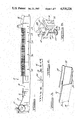
FIG. 1 is a side elevation view of a roll-forming apparatus, including sweep-forming apparatus according to the present invention.
FIG. 2 is a top view of an exemplary arcuate automotive bumper, illustrating one type of article which may be formed by the roll-forming apparatus of FIG. 1.
FIG. 3 is a partial cross-sectional perspective view of the automotive bumper of FIG. 2.
FIG. 4 is an enlarged side elevation view of the sweep-forming apparatus of FIG. 1.
FIG. 5 is a plan view of the support platform portions of the sweep-forming apparatus of FIG. 4.
FIG. 6 is a partial perspective view of the support platform structure of FIG. 5, diagramatically illustrating a mechanism for selectively adjusting the transverse position of the sweep-forming stations of FIG. 5 in a transverse direction generally perpendicular to the longitudinal path of the workpiece.
FIG. 7 is an enlarged side elevation view of one of the stations of the sweep apparatus of FIG. 4, with one of its supporting stands removed to reveal the various forming components therein.
FIG. 8 is a partial end view of the entrance of the sweepforming station of FIG. 7, with various components removed for clarity.
FIG. 9 is an end view of the exit of the sweep-forming station illustrated in FIG. 7.
FIG. 10 is a partial top view of the sweep-forming station of FIG. 7, with various components removed for clarity.
FIG. 11 is a sectional view taken along line 11--11 of FIG. 10.
DETAILED DESCRIPTION OF THE PREFERRED EMBODIMENTS
FIGS. 1 through 11 of the drawings depict, for purposes of illustration, an exemplary roll-forming line, including sweep-forming apparatus according to the present invention. One skilled in the art will readily recognize from the following discussion that the principles of the present invention are equally applicable to roll-forming equipment other than that shown in the drawings.
Referring to FIG. 1, an exemplary roll-forming line 10, generally includes a coil holder 12 for dispensing a coiled strip of sheet material 14, a feeding and leveling apparatus 16, and an end-welder machine 18 for longitudinally feeding the sheet material 14 into one or more roll-forming sections 20. The roll-forming sections 20 each include a number of serially-located sets of forming rolls (not shown) that progressively deform the sheet material 14 as it is longitudinally fed therethrough in order to ultimately form the sheet material into a desired configuration and cross-sectional shape. According to the present invention, the roll-forming line 10 includes a sweep-forming apparatus 22, preferably located at the end or exit of the series of roll-forming sections 20. The sweep-forming apparatus 22 functions, as is described further below, to introduce a generally longitudinally-extending sweep or curvature into the previously-formed sheet material 14. Typically, the roll-forming line 10 may also include an automatic cut-off machine 24 and a conveyor mechanism 26 for transporting the finished product to another location in the fabricating facility.
FIGS. 2 and 3 illustrate, for purposes of illustration only, a longitudinally-extending automotive bumper 30 which exemplifies one type of product which may be formed or fabricated on equipment such as the roll-forming line 10 having a sweep-forming apparatus 22 according to the present invention. The exemplary automotive bumper 30 is generally U-shaped and includes an upper portion 32, an outer portion 34, and a lower portion 36. Typically, a pair of flanges 38 and 40 protrude inwardly toward each other from the upper and lower portions 32 and 36, respectively. As described herein with respect to the roll-forming line 10 and the sweepforming apparatus 22, both the interior and exterior surfaces of the outer portion 34 and the flanges 38 and 40 are referred to as "lateral" or "laterally-extending" surfaces. Correspondingly, both the interior and exterior surfaces of the upper and lower portions 32 and 36 are referred to as "transverse" or "transversely-extending" surfaces.
In one embodiment of the present invention, automotive bumpers such as that depicted by reference number 30 in FIGS. 2 and 3, were fabricated from high-strength, low-alloy (HSLA) steel having a yield strength in the range of approximately 45,000 p.s.i. to approximately 200,000 p.s.i., with a degree of curvature or sweep up to approximately "no. 30" sweep. The "sweep number" refers to the relationship of the chord depth 44 shown in FIG. 2, to the overall length of the chord 46. For example, a "no. 10 sweep" refers to a maximum chord depth of ten-eighths (10/8") inch over a five-foot increment of chord length. It was found during the actual development and construction of a sweep-forming apparatus according to the present invention that such degrees of curvature could be introduced into elongated, high-strength, low-alloy steel articles that have already been formed into their final desired cross-sectional shapes without affecting or damaging the previously-formed cross-sectional shape of the article.
FIG. 4 illustrates an enlarged side elevational view of the exemplary sweep-forming apparatus 22, which generally includes a base assembly 52, a number of articulated and pivotally interconnected support platforms 54, and a corresponding number of forming station assemblies 56 supportably secured to the support platforms 54. It should be noted that although three forming stations are depicted for purposes of illustration in the exemplary sweep-forming apparatus 22, a greater or lesser number of forming stations may alternatively be employed in a particular application. As will become apparent from the discussion herein, the exact number of forming stations depends upon various factors, such as the degree of curvature or sweep to be introduced into the formed elongated article, the type of material being formed, and the cross-sectional shape of the article, for example.
The position of the support platforms 54 relative to the base assembly 52 can preferably be adjustably increased or decreased in a transverse direction, and the platforms can be rotated relative to the base assembly 52 in order to form the desired degree of sweep in the elongated article. Such adjustments are facilitated in the preferred embodiment by a number of adjustment mechanisms 58 provided at both lateral sides and at both longitudinal ends of each support platform 54. As illustrated in FIGS. 5 and 6, the adjustment mechanisms 58 each generally include a generally transversely-extending threaded adjusting screw 60 fixed for rotation with a worm wheel 62 meshed with, and rotatably driven by, a worm gear 64. The adjusting screws 60 are threadably engaged with each end of a number of anchor bars 66. Each anchor bar 66 extends laterally through generally circular openings in a number of longitudinally-extending arms 68 on adjacent support platforms 54 and through elongated openings in a lock bracket 70 at each of its lateral ends.
As the adjusting screws 60 are rotated by the interaction of their associated worm gears 64 and worm wheels 62, they threadably urge the anchor bars 66 in a transverse direction toward or away from the base assembly 52. The support platforms 54, which are pivotally connected to the anchor bars 66 by way of their longitudinally-extending arms 68, are therefore also moved toward or away from the base assembly 52 in order to adjust the transverse position of the forming station assemblies 56 for the desired degree of sweep or curvature in the item being formed. As shown in FIG. 4, by adjusting the transverse position of the anchor bars 66, the center line 72 of each forming station 56 can be maintained in a generally perpendicular relationship with the tangential path 74 of the workpiece as it is passed longitudinally through the forming station. Once the above-described adjustments are made, the adjustment mechanisms 58 are secured to the base assembly 52 by locking bolts or other suitable securing means, and the anchor bars 66 are secured to the lock bracket 70 by locking nuts 76 or other suitable locking means, in order to maintain the support platforms 54 in their adjusted positions.
It should be noted the corresponding adjustment mechanisms 58 at each end of an anchor bar may optionally be interconnected by a common drive shaft drivingly interconnecting their respective worm gears 64 in order to simultaneously adjust the position of both lateral ends of their associated anchor bars by the same amount. Alternatively, such adjustments may optionally be driven by independent worm gears at each lateral end of each anchor bar in order to accommodate unusual forming conditions necessitating independent lateral adjustment capabilities.
Generally, each forming station 56 at least includes a pair of laterally-spaced corresponding stand assemblies 80 adapted for supporting one or more driven roll shafts 82 that drivingly carry forming rolls (described below) that conformingly engage opposite lateral surfaces of the previously-formed bumper 30 therebetween. The stand assemblies 80, as well as other components of forming stations 56, are connected with their respective support platforms 54 and thus may also be adjustably pivoted and transversely moved therewith.
For purposes of illustration, FIGS. 7 through 11 generally depict the various sweep-forming components of the intermediate, or second, of the three sweep-forming stations 56 of the exemplary sweep-forming apparatus 22. The sweep-forming station 56 generally includes a pair of corresponding forming rolls 84 and 86 mounted on the roll shafts 82 for rotation therewith, an entrance-side constraining assembly 90 secured to the stand assembly 80 at the entrance side of the sweep-forming station, and a transversely and longitudinally offset forming roll 94 mounted on the exit-side of the constraining assembly 92. It should be noted that the workpiece is preferably driven in a longitudinal direction by the forming rolls 84 and 86, which conformingly engage opposite lateral surfaces of the bumper outer portion 34.
As shown in FIG. 8, the longitudinally-moving elongated workpiece (here the bumper 30) enters the constraining assembly 90 and is substantially constrained in its desired cross-sectional configuration during the sweep-forming operation. A pair of suitably-shaped outside arbors 96 slidably and conformingly engage the exterior transverse surfaces of the portions 32 and 36 of the bumper 30, a back-up shoe 98 slidably and conformingly engages the exterior lateral surface of the bumper portion 34, and a pair of constraining arbors 100 slidably and conformingly engage the exterior lateral surfaces of bumper flanges 38 and 40, in order to constrain substantially all of the entire exterior lateral and transverse surfaces of the bumper 30. The outside arbors 96, back-up shoe 98, and the constraining arbors 100 are all connected to a fixed body portion 102 of the constraining assembly 90. In the preferred embodiment, the interior surfaces of the bumper 30 are constrained by a suitably-shaped insert member 104 and a pair of articulated interior or "snake" arbors 106 that slidably engage the interior surfaces of the bumper 30. The insert member 104 is secured to a guide block 108, which is in turn secured to the fixed body portion 102. The snake arbors 106 each include a number of specially-shaped arbor blocks 110 that are longitudinally interconnected by at least one tie rod 112 that is anchored to the guide block 108 by a retainer plate 114.
FIG. 9 illustrates the interaction of the exit-end constraining assembly 92 with the bumper 30 in the exemplary sweep-forming apparatus 22 according to the present invention. Like the constraining assembly 90, the exit-end constraining assembly 92 generally includes a pair of suitably-shaped outside arbors 116 that slidably and conformingly engage the exterior transverse surfaces of the bumper portions 32 and 36, a back-up shoe 118 that slidably and conformingly engages the exterior lateral surfaces of the bumper portion 34, and a pair of constraining arbors 120 that slidably and conformingly engage the exterior lateral surfaces of the bumper flanges 38 and 40. The interior surfaces of the bumper 30 are similarly constrained by the sliding and conforming engagement arbor blocks 110 of the snake arbors 106 and an insert member 122 secured to a guide block 124. The outside arbors 116, and back-up shoe 118, the constraining arbors 120, the insert member 122, and the guide block 124 are all connected to a fixed body portion 126 of the constraining assembly 92.
As the bumper 30 moves longitudinally through the area between the entrance-end constraining assembly 90 and the exit-end constraining assembly 92, it is substantially constrained by the driven forming rolls 84 and 86, a pair of idler rolls 130 and the snake arbors 106. The idler rolls 130 are rotatable about generally transversely-extending axes, and have outer surfaces that conformingly engage the exterior transverse surfaces of the bumper 30. The snake arbors 106 longitudinally extend generally from the exit area of the constraining assembly 90 into the entrance area of the constraining assembly 92. The tie rods 112 extend through longitudinal openings 132 in the individual arbor blocks 110 that are sized to allow a substantial amount of clearance between the tie rods 112 and the openings 132. Thus the individual arbor blocks 110 are allowed to pivot, or articulate, in a transverse direction so that the snake arbors 106 can slidably constrain and conform to the interior of the bumper 30 as the sweep or curvature is introduced therein.
The bumper 30 in the exemplary sweep-forming apparatus 22 is permanently deformed to introduce a sweep therein primarily by the interaction of the forming rolls 84 and 86 and the forming roll 94 at the middle or intermediate sweep-forming station 72. In the exemplary embodiment, the rolls at the first and third sweep-forming stations primarily serve the function of guiding the bumper 30 as it is passed to and from the second or intermediate station. Thus during the forming of the sweep, the longitudinally-moving bumper 30 is substantially constrained over substantially all of its interior and exterior surfaces, both lateral and transverse. During the development and construction of an actually-constructed embodiment of the exemplary sweep-forming apparatus 22, it was found that by substantially constraining such surfaces during the sweep-forming operation, the previously-formed cross-sectional shape and configuration of the moving elongated article could be maintained without the introduction of undesirable wrinkles, folds or other undesired deformations. Thus, the present invention allows an elongated article to be roll-formed to a desired final cross-section, using conventional and easy-to-control roll-forming techniques, and then permanently deformed in a transverse direction into a desired swept or curved configuration without disturbing or damaging the previously-formed article. Furthermore, the present invention may be so employed in the forming of high-strength materials, such as high-strength, low-alloy (HSLA) steels, for example.
It should be emphasized that although the exemplary sweepforming apparatus 22 includes three serially-disposed sweep-forming stations, with only the second or middle station including the entrance and exit constraining assemblies 90 and 92, the invention is not limited to such a construction. From the foregoing discussion, one skilled in the art will now readily recognize that any number of stations may be employed, and that one or more of such stations may include the constraining assemblies discussed above, in a particular application. The exact number of stations and constraining assemblies necessary or desirable in a particular application depends upon factors such as the properties of the material being formed, the cross-sectional configuration of the article being formed, and the desired amount of sweep or curvature, for example.
The foregoing discussion discloses and describes exemplary embodiments of the present invention. One skilled in the art will readily recognize from such discussion that various changes, modifications and variations may be made therein without departing from the spirit and scope of the invention as defined in the following claims.

Claims (11)

What is claimed is:
1. An apparatus for introducing a sweep into an elongated article having a predetermined cross-sectional shape and defining an interior surface and an exterior surface comprising:
first and second pinch roll driving means in rolling engagement with said article for driving said article in a longitudinal direction;
roll-forming means disposed longitudinally subsequent to said first and second pinch roll driving means for introducing a sweep into said elongated article;
constraining means for preventing change in said predetermined cross-sectional shape including,
(a) an entrance guide means fixed relative to said first and second driving means and disposed longitudinally precedent to said first and second driving means, said entrance guide means having means for slidingly supporting substantially the entire exterior surface of said article as it enters engagement with said driving means;
(b) an exit guide means fixed relative to said first and second driving means and disposed longitudinally subsequent to said first and second driving means and disposed both longitudinally precedent and subsequent to said roll-forming means, said exit guide means having means for slidingly supporting substantially the entire exterior surface of said article as it exits from engagement with said driving means;
(c) internal supporting means comprising at least two elongated and parallel snake arbor means extending longitudinally between said entrance guide means and said exit guide means and disposed on axially opposite sides of said first pinch roll driving means, said internal supporting means slidingly supporting substantially the entire interior surface of said article as it enters engagement with said driving means and as it exits engagement with said driving means; and
(d) means disposed generally between said entrance and exit guide means for supporting said exterior surface of said article as it passes between said entrance and exit guide means.
2. The apparatus according to claim 1 wherein said means for supporting said exterior surface of said article as it passes between said entrance and exit guide means includes at least one idler roll.
3. The apparatus of claim 1 wherein each of said snake arbor means includes a plurality of tie rods extending longitudinally therethrough.
4. The apparatus of claim 1, further comprising a base, a support platform for carrying at least said first and said second pinch roll driving means, and adjustment means for interconnecting said platform with said base.
5. The apparatus of claim 4 wherein said adjustment means comprises means for adjusting the spatial relationship of said platform to said base.
6. The apparatus of claim 4 wherein said adjustment means comprises means for raising and lowering said platform relative to said base.
7. The apparatus according to claim 1 further comprising at least one forming station having third and fourth pinch roll driving means, said forming station disposed longitudinally precedent to said first and second pinch roll driving means.
8. The apparatus of claim 1 further comprising forming station having third and fourth pinch roll driving means, said forming station disposed longitudinally subsequent to said roll-forming means.
9. The apparatus according to claim 1 further comprising a first forming station having third and fourth pinch roll driving means disposed longitudinally precedent to said first and second pinch roll driving means; and second forming station having fifth and sixth pinch roll driving means disposed longitudinally subsequent to said roll-forming means.
10. The apparatus of claim 9 wherein each of said forming stations includes a platform, a base, and adjustment means for connecting said platform to said base.
11. The apparatus of claim 10 wherein said adjustment means are operable to independantly raise and lower said platforms relative to said bases.
US06/503,405 1983-06-13 1983-06-13 Sweep-forming apparatus Expired - Lifetime US4530226A (en)

Priority Applications (1)

Application Number Priority Date Filing Date Title
US06/503,405 US4530226A (en) 1983-06-13 1983-06-13 Sweep-forming apparatus

Applications Claiming Priority (1)

Application Number Priority Date Filing Date Title
US06/503,405 US4530226A (en) 1983-06-13 1983-06-13 Sweep-forming apparatus

Publications (1)

Publication Number Publication Date
US4530226A true US4530226A (en) 1985-07-23

Family

ID=24001953

Family Applications (1)

Application Number Title Priority Date Filing Date
US06/503,405 Expired - Lifetime US4530226A (en) 1983-06-13 1983-06-13 Sweep-forming apparatus

Country Status (1)

Country Link
US (1) US4530226A (en)

Cited By (18)

* Cited by examiner, † Cited by third party
Publication number Priority date Publication date Assignee Title
US5092512A (en) * 1990-03-26 1992-03-03 Shape Corporation Method of roll-forming an automotive bumper
US5104026A (en) * 1990-03-26 1992-04-14 Shape Corporation Apparatus for roll-forming an automotive bumper
US5306058A (en) * 1990-03-26 1994-04-26 Shape Corporation Tubular roll-formed automotive bumper
US5395036A (en) * 1990-03-26 1995-03-07 Shape Corporation Method of roll-forming an end automotive bumper
EP0870650A3 (en) * 1997-04-10 1999-12-01 Hyundai Motor Company Apparatus and method for making an automotive bumper beam
WO2001051228A2 (en) * 2000-01-14 2001-07-19 Cosma International, Inc. A sweep forming assembly, a bumper and a method of manufacture thereof
US6386011B1 (en) 2001-01-18 2002-05-14 Tishken Products Co. Adjustable cut off apparatus for elongated articles having varying degrees of sweep
US6520215B2 (en) 2001-02-27 2003-02-18 Hayes-Albion Corporation Tubular bar with integral rolled locking system and method of making same
US6557318B2 (en) 2001-05-07 2003-05-06 Trim Trends Co, Llc Expandable link system and method of making same
US20050120767A1 (en) * 2003-10-14 2005-06-09 Bair Jerry P. Sweep unit assembly
US20060277960A1 (en) * 2005-06-13 2006-12-14 Shape Corporation Roll-former apparatus with rapid-adjust sweep box
US20070180880A1 (en) * 2005-06-13 2007-08-09 Shape Corporation Roll-former apparatus with rapid-adjust sweep box
US20100011829A1 (en) * 2006-08-23 2010-01-21 Metform International Ltd. Roll-forming machine for forming smooth curves in profiled panel sections and method of forming curved panels
EP2234738A1 (en) * 2007-12-12 2010-10-06 Allied Tube & Conduit Corporation Arching metallic profiles in continuous in-line process
CN101983795A (en) * 2010-08-30 2011-03-09 张家港市明华机械制造有限公司 Rotation actuating device of feeding shaft sleeve on pipe bender
US20110067473A1 (en) * 2009-09-21 2011-03-24 Heinz Richard D Method of Forming Three-Dimensional Multi-Plane Beam
US20110094278A1 (en) * 2008-02-12 2011-04-28 Cml International S.P.A. Method to check and control a roller bending machine for continuously bending an elongated workpiece at variable curvature radii, and machine so controlled
WO2011085776A1 (en) * 2010-01-15 2011-07-21 Axel Weber Device for rollforming-profiling and bowing sections of metal strip

Citations (27)

* Cited by examiner, † Cited by third party
Publication number Priority date Publication date Assignee Title
US520865A (en) * 1894-06-05 Apparatus for cambering rails
US592767A (en) * 1897-11-02 Flanging-machine
US1351472A (en) * 1919-09-12 1920-08-31 James E Conway Bending-machine
US1856597A (en) * 1931-06-09 1932-05-03 Arthur E Stjarnstrom Flexible mandrel
US1908373A (en) * 1931-03-25 1933-05-09 Gen Fire Extinguisher Co Method of making pipe bends or the like
GB453623A (en) * 1935-08-03 1936-09-15 Frank Ernest Bullock Improvements in the manufacture of split or divided metal bushes
US2143442A (en) * 1936-05-11 1939-01-10 Motor Products Corp Metal working machine
US2150731A (en) * 1937-10-05 1939-03-14 Vickers Armstrongs Ltd Method of and means for rolling channel or like sections from strip metal
US2701002A (en) * 1952-05-26 1955-02-01 Elkhart Screw Products Inc Apparatus for making pipe couplings or fixtures
GB898664A (en) * 1959-11-12 1962-06-14 David Erhmon Armstrong Cold tube bending and sizing with or without shouldering
US3144071A (en) * 1960-08-10 1964-08-11 Godins The Rollers Of Steel Se Machines for forming metal sections or tubes
US3473361A (en) * 1967-04-06 1969-10-21 Teledyne Inc Method and apparatus for bending tubing
US3490259A (en) * 1967-09-13 1970-01-20 Teledyne Inc Tube bending mandrel
US3491569A (en) * 1965-09-03 1970-01-27 Gazi Sabirov Method of manufacturing double-curvature sheets
US3491562A (en) * 1966-10-12 1970-01-27 Hitachi Ltd System and apparatus for effecting a correction of deflection of strip steel from its normal path of travel in a tandem rolling mill
US3529461A (en) * 1968-11-15 1970-09-22 Knudson Gary Art Roll forming method and machine
US3610011A (en) * 1969-06-02 1971-10-05 Clark J Valentine Unitary roll formed vehicle fender and apparatus and method for producing the same
US3842473A (en) * 1971-12-22 1974-10-22 Glacier Metal Co Ltd Bearings
US3938360A (en) * 1973-05-02 1976-02-17 Hitachi, Ltd. Shape control method and system for a rolling mill
US4080815A (en) * 1975-06-09 1978-03-28 The Boeing Company Pinch and forming roll assembly for numerically controlled contour forming machines
SU617112A1 (en) * 1977-02-25 1978-07-30 Предприятие П/Я Г-4744 Profile and tube bending apparatus
US4117702A (en) * 1977-06-06 1978-10-03 The Boeing Company Rolling machines for contouring tapered structural members
US4123930A (en) * 1977-03-29 1978-11-07 Teledyne Industries, Inc. Mandrel for bending tubes
US4154077A (en) * 1978-03-06 1979-05-15 Field Form, Inc. Apparatus and method for manufacturing curved building panels
US4176539A (en) * 1977-03-25 1979-12-04 Hitachi Metals, Inc. Cold-roll forming stand
US4273232A (en) * 1977-10-28 1981-06-16 Hitachi, Ltd. Passenger conveyor balustrade
US4354372A (en) * 1978-03-08 1982-10-19 Hitachi Metals, Ltd. Method and apparatus for cold roll forming metal strip

Patent Citations (27)

* Cited by examiner, † Cited by third party
Publication number Priority date Publication date Assignee Title
US520865A (en) * 1894-06-05 Apparatus for cambering rails
US592767A (en) * 1897-11-02 Flanging-machine
US1351472A (en) * 1919-09-12 1920-08-31 James E Conway Bending-machine
US1908373A (en) * 1931-03-25 1933-05-09 Gen Fire Extinguisher Co Method of making pipe bends or the like
US1856597A (en) * 1931-06-09 1932-05-03 Arthur E Stjarnstrom Flexible mandrel
GB453623A (en) * 1935-08-03 1936-09-15 Frank Ernest Bullock Improvements in the manufacture of split or divided metal bushes
US2143442A (en) * 1936-05-11 1939-01-10 Motor Products Corp Metal working machine
US2150731A (en) * 1937-10-05 1939-03-14 Vickers Armstrongs Ltd Method of and means for rolling channel or like sections from strip metal
US2701002A (en) * 1952-05-26 1955-02-01 Elkhart Screw Products Inc Apparatus for making pipe couplings or fixtures
GB898664A (en) * 1959-11-12 1962-06-14 David Erhmon Armstrong Cold tube bending and sizing with or without shouldering
US3144071A (en) * 1960-08-10 1964-08-11 Godins The Rollers Of Steel Se Machines for forming metal sections or tubes
US3491569A (en) * 1965-09-03 1970-01-27 Gazi Sabirov Method of manufacturing double-curvature sheets
US3491562A (en) * 1966-10-12 1970-01-27 Hitachi Ltd System and apparatus for effecting a correction of deflection of strip steel from its normal path of travel in a tandem rolling mill
US3473361A (en) * 1967-04-06 1969-10-21 Teledyne Inc Method and apparatus for bending tubing
US3490259A (en) * 1967-09-13 1970-01-20 Teledyne Inc Tube bending mandrel
US3529461A (en) * 1968-11-15 1970-09-22 Knudson Gary Art Roll forming method and machine
US3610011A (en) * 1969-06-02 1971-10-05 Clark J Valentine Unitary roll formed vehicle fender and apparatus and method for producing the same
US3842473A (en) * 1971-12-22 1974-10-22 Glacier Metal Co Ltd Bearings
US3938360A (en) * 1973-05-02 1976-02-17 Hitachi, Ltd. Shape control method and system for a rolling mill
US4080815A (en) * 1975-06-09 1978-03-28 The Boeing Company Pinch and forming roll assembly for numerically controlled contour forming machines
SU617112A1 (en) * 1977-02-25 1978-07-30 Предприятие П/Я Г-4744 Profile and tube bending apparatus
US4176539A (en) * 1977-03-25 1979-12-04 Hitachi Metals, Inc. Cold-roll forming stand
US4123930A (en) * 1977-03-29 1978-11-07 Teledyne Industries, Inc. Mandrel for bending tubes
US4117702A (en) * 1977-06-06 1978-10-03 The Boeing Company Rolling machines for contouring tapered structural members
US4273232A (en) * 1977-10-28 1981-06-16 Hitachi, Ltd. Passenger conveyor balustrade
US4154077A (en) * 1978-03-06 1979-05-15 Field Form, Inc. Apparatus and method for manufacturing curved building panels
US4354372A (en) * 1978-03-08 1982-10-19 Hitachi Metals, Ltd. Method and apparatus for cold roll forming metal strip

Non-Patent Citations (6)

* Cited by examiner, † Cited by third party
Title
"Hitachi Cold Roll Forming Lines"--Hitachi Metals, Ltd.
"HSLA Bumpers From a Rollformer"--American Machinist, Aug. 1982.
"Suppliers Play Big Role in Roll-Formed Bumpers"--Ward's Auto World 7/82.
Hitachi Cold Roll Forming Lines Hitachi Metals, Ltd. *
HSLA Bumpers From a Rollformer American Machinist, Aug. 1982. *
Suppliers Play Big Role in Roll Formed Bumpers Ward s Auto World 7/82. *

Cited By (38)

* Cited by examiner, † Cited by third party
Publication number Priority date Publication date Assignee Title
US5092512A (en) * 1990-03-26 1992-03-03 Shape Corporation Method of roll-forming an automotive bumper
US5104026A (en) * 1990-03-26 1992-04-14 Shape Corporation Apparatus for roll-forming an automotive bumper
US5306058A (en) * 1990-03-26 1994-04-26 Shape Corporation Tubular roll-formed automotive bumper
US5395036A (en) * 1990-03-26 1995-03-07 Shape Corporation Method of roll-forming an end automotive bumper
US5454504A (en) * 1990-03-26 1995-10-03 Shape Corporation Apparatus for roll-forming end bumper for vehicles
US5566874A (en) * 1990-03-26 1996-10-22 Shape Corporation Apparatus for forming an end bumper for vehicles
US5813594A (en) * 1990-03-26 1998-09-29 Shape Corporation Apparatus for forming an end bumper for vehicles
EP0870650A3 (en) * 1997-04-10 1999-12-01 Hyundai Motor Company Apparatus and method for making an automotive bumper beam
WO2001051228A2 (en) * 2000-01-14 2001-07-19 Cosma International, Inc. A sweep forming assembly, a bumper and a method of manufacture thereof
WO2001051228A3 (en) * 2000-01-14 2002-10-24 Cosma Int Inc A sweep forming assembly, a bumper and a method of manufacture thereof
US6820451B2 (en) 2000-01-14 2004-11-23 Magna International Inc. Sweep forming assembly and method
US20050062299A1 (en) * 2000-01-14 2005-03-24 Magna International Inc. Sweep forming assembly and method
US6386011B1 (en) 2001-01-18 2002-05-14 Tishken Products Co. Adjustable cut off apparatus for elongated articles having varying degrees of sweep
US6520215B2 (en) 2001-02-27 2003-02-18 Hayes-Albion Corporation Tubular bar with integral rolled locking system and method of making same
US6840571B1 (en) 2001-02-27 2005-01-11 Trim Trends Co, Inc. Tubular bar with integral rolled locking system and method of making same
US6557318B2 (en) 2001-05-07 2003-05-06 Trim Trends Co, Llc Expandable link system and method of making same
US20050120767A1 (en) * 2003-10-14 2005-06-09 Bair Jerry P. Sweep unit assembly
US7360386B2 (en) 2003-10-14 2008-04-22 Century, Inc. Sweep unit assembly
US20070180880A1 (en) * 2005-06-13 2007-08-09 Shape Corporation Roll-former apparatus with rapid-adjust sweep box
US20080047315A1 (en) * 2005-06-13 2008-02-28 Lyons Bruce W Method utilizing power adjusted sweep device
US7337642B2 (en) 2005-06-13 2008-03-04 Shape Corporation Roll-former apparatus with rapid-adjust sweep box
US20080053178A1 (en) * 2005-06-13 2008-03-06 Lyons Bruce W Power adjusted sweep device
US20060277960A1 (en) * 2005-06-13 2006-12-14 Shape Corporation Roll-former apparatus with rapid-adjust sweep box
US7530249B2 (en) 2005-06-13 2009-05-12 Shape Corp. Method utilizing power adjusted sweep device
US7882718B2 (en) 2005-06-13 2011-02-08 Shape Corp. Roll-former apparatus with rapid-adjust sweep box
US20100011829A1 (en) * 2006-08-23 2010-01-21 Metform International Ltd. Roll-forming machine for forming smooth curves in profiled panel sections and method of forming curved panels
EP2234738A1 (en) * 2007-12-12 2010-10-06 Allied Tube & Conduit Corporation Arching metallic profiles in continuous in-line process
US20120131974A1 (en) * 2007-12-12 2012-05-31 Allied Tube & Conduit Corporation Arching metallic profiles in continous in-line process
EP2234738A4 (en) * 2007-12-12 2013-09-18 Allied Tube & Conduit Corp Arching metallic profiles in continuous in-line process
US20110094278A1 (en) * 2008-02-12 2011-04-28 Cml International S.P.A. Method to check and control a roller bending machine for continuously bending an elongated workpiece at variable curvature radii, and machine so controlled
US8646300B2 (en) * 2008-02-12 2014-02-11 Cml International S.P.A. Method and controlled machine for continuous bending
US8763437B2 (en) 2009-09-21 2014-07-01 Shape Corp. Roll former with three-dimensional sweep unit
US20110067473A1 (en) * 2009-09-21 2011-03-24 Heinz Richard D Method of Forming Three-Dimensional Multi-Plane Beam
US20110067472A1 (en) * 2009-09-21 2011-03-24 Heinz Richard D Roll Former With Three-Dimensional Sweep Unit
US8333095B2 (en) 2009-09-21 2012-12-18 Shape Corp. Roll former with three-dimensional sweep unit
US8333096B2 (en) 2009-09-21 2012-12-18 Shape Corp. Method of forming three-dimensional multi-plane beam
WO2011085776A1 (en) * 2010-01-15 2011-07-21 Axel Weber Device for rollforming-profiling and bowing sections of metal strip
CN101983795A (en) * 2010-08-30 2011-03-09 张家港市明华机械制造有限公司 Rotation actuating device of feeding shaft sleeve on pipe bender

Similar Documents

Publication Publication Date Title
US4530226A (en) Sweep-forming apparatus
US7882718B2 (en) Roll-former apparatus with rapid-adjust sweep box
US5926930A (en) Apparatus for producing rigid elongated member for use in vehicles
US6820451B2 (en) Sweep forming assembly and method
DE2813636C3 (en) Process and device for the production of profiles made of metal, primarily steel profiles
US6148654A (en) Convertible roll forming apparatus
EP2480354B1 (en) Roll former with three-dimensional sweep unit and method
US20060277960A1 (en) Roll-former apparatus with rapid-adjust sweep box
US5970764A (en) Roll forming apparatus
CA1119849A (en) Line pipe forming apparatus and method
US4526024A (en) Apparatus for forming elongated sheet metal panels
US6282932B1 (en) Axial and transverse roller die adjustment apparatus and method
EP1537922B1 (en) Manufacturing profiles having a cross-section varying in longitudinal direction
US6286352B1 (en) Stretch roll forming apparatus using frusto-conical rolls
JPH0615372A (en) Method and device for manufacturing rail and rail
US7360386B2 (en) Sweep unit assembly
EP1484123B1 (en) Method and apparatus for manufacturing a bent profile
CN109335795B (en) Production process and production line for special-shaped material for mounting scraping strips
US3468150A (en) Cluster roll assembly for tube mills
RU2755138C1 (en) Installation for profiling metal tape
RU2019333C1 (en) Machine for bending rolled sheets
SU1600869A1 (en) Rolling mill
SU1454541A1 (en) Method of producing roll-formed sections
CN117681631A (en) Volute section bar, volute car door anti-collision rod and machining method of volute car door anti-collision rod
SU1480919A1 (en) Method of producing semiclosed z-section rolled shapes

Legal Events

Date Code Title Description
AS Assignment

Owner name: TISHKEN PRODUCTS INC., 13000 W. EIGHT MILE ROAD, O

Free format text: ASSIGNMENT OF ASSIGNORS INTEREST.;ASSIGNORS:GRANZOW, CARL F.;LASH, EDWARD G.;GLEASON, EVERETT;AND OTHERS;REEL/FRAME:004141/0755

Effective date: 19830609

STCF Information on status: patent grant

Free format text: PATENTED CASE

FEPP Fee payment procedure

Free format text: PAYOR NUMBER ASSIGNED (ORIGINAL EVENT CODE: ASPN); ENTITY STATUS OF PATENT OWNER: SMALL ENTITY

FPAY Fee payment

Year of fee payment: 4

FPAY Fee payment

Year of fee payment: 8

FPAY Fee payment

Year of fee payment: 12