US1908373A - Method of making pipe bends or the like - Google Patents
Method of making pipe bends or the like Download PDFInfo
- Publication number
- US1908373A US1908373A US525166A US52516631A US1908373A US 1908373 A US1908373 A US 1908373A US 525166 A US525166 A US 525166A US 52516631 A US52516631 A US 52516631A US 1908373 A US1908373 A US 1908373A
- Authority
- US
- United States
- Prior art keywords
- pipe
- bend
- mandrel
- making
- cut
- Prior art date
- Legal status (The legal status is an assumption and is not a legal conclusion. Google has not performed a legal analysis and makes no representation as to the accuracy of the status listed.)
- Expired - Lifetime
Links
- 238000004519 manufacturing process Methods 0.000 title description 9
- 238000005452 bending Methods 0.000 description 6
- 238000000034 method Methods 0.000 description 5
- 241000220010 Rhode Species 0.000 description 2
- 230000015572 biosynthetic process Effects 0.000 description 1
- 229910052729 chemical element Inorganic materials 0.000 description 1
- 230000000295 complement effect Effects 0.000 description 1
- 230000006835 compression Effects 0.000 description 1
- 238000007906 compression Methods 0.000 description 1
- 230000008602 contraction Effects 0.000 description 1
- 238000010438 heat treatment Methods 0.000 description 1
- 230000010355 oscillation Effects 0.000 description 1
- 238000007493 shaping process Methods 0.000 description 1
- 230000037303 wrinkles Effects 0.000 description 1
Images
Classifications
-
- B—PERFORMING OPERATIONS; TRANSPORTING
- B21—MECHANICAL METAL-WORKING WITHOUT ESSENTIALLY REMOVING MATERIAL; PUNCHING METAL
- B21D—WORKING OR PROCESSING OF SHEET METAL OR METAL TUBES, RODS OR PROFILES WITHOUT ESSENTIALLY REMOVING MATERIAL; PUNCHING METAL
- B21D7/00—Bending rods, profiles, or tubes
- B21D7/08—Bending rods, profiles, or tubes by passing between rollers or through a curved die
-
- Y—GENERAL TAGGING OF NEW TECHNOLOGICAL DEVELOPMENTS; GENERAL TAGGING OF CROSS-SECTIONAL TECHNOLOGIES SPANNING OVER SEVERAL SECTIONS OF THE IPC; TECHNICAL SUBJECTS COVERED BY FORMER USPC CROSS-REFERENCE ART COLLECTIONS [XRACs] AND DIGESTS
- Y10—TECHNICAL SUBJECTS COVERED BY FORMER USPC
- Y10T—TECHNICAL SUBJECTS COVERED BY FORMER US CLASSIFICATION
- Y10T29/00—Metal working
- Y10T29/49—Method of mechanical manufacture
- Y10T29/49428—Gas and water specific plumbing component making
- Y10T29/49444—Elbow or L-shaped fitting making
Definitions
- This invention relates to an improved method of making pipe bends or the like.
- the principal object of this invention is to produce pipe bends having the same diametrical and circumferential size as the pipe from which the bend is made, and having the same uniform thickness of wall as in the original pipe. It is a feature of the invention that its method may be applied in making bends integrally at the end of a pipe as well as 1n forming bends per se.
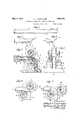
- Figure 1 is a side elevation of a single pipe length with a dot-and-dash transverse line indicating how it should be cut to provlde for the formation of a 90 bend on'the end of the pipe length, as well as a 90 bend per se;
- Figure 2 is a similar view of the plpe after being cut with the bend to be formed illustrated in dot-dash outline;
- Figure 3 is a similar View of the portion of the pipe of Figure l that is cut off, showing in dot-dash outline the bend to be formed therefrom;
- Figure 4 is an elevation in section as on line 44 of Figure 5 of apparatus adapted for making the pipe bends in accordance with this invention.
- Figure 5 is an end elevation of the apparatus of Figure 4.
- Figures 6 and 7 are views similar to Figure 4 showing the relative positions of the bend and parts of the apparatus at an intermediate and at the final stage of the bending;
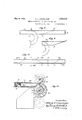
- Figure 8 shows how a pipe may be cutto provide a half bend, the latter being suggested in dot-dash outline
- Figure 9 shows the cut-ofl' end of the pipe of Figure 8, with the bend to be formed therefrom in dot-dash outline;
- Figure 10 illustrates another 'manner of cutting a pipe to form both quarter-bends and half-bends
- Figure 11 shows apparatus bends.
- apipe 1 of the same diametrical and circumferential size as the desired bend is cut cross-wise or slant-wise on a plane passing through points a and d.
- Figure 8 represents how a pipe may be cut to produce a half-turn bend on the pipe 12, and a similar return bend per se.
- the point 9 is located at a distance from the endof the pipe corresponding with the length of the innermost element In of the bend to be formed, and the point 7' is similarly located, its distanoe from the end of the pipe being that of the element kl of the proposed bend.
- a halfturn bend may be formed on the pipe 12 (indicated in Figure 8) and a'similar bend shaped from the cut-off end 12, (indicated in Figure 9).
- Figure 10 suggests how a pipe 13 may be out into sections adapted to be made into both quarter-turns and half-turns. Sections 13a and 136 at the ends of the pipes are to be cut on the lines mm the points m and .n being located in the same way as were.
- v and distance 927' is likewise twice the distance from the pipe end to point m.
- the section 1301 of the pipe is the same as section 130. It is to be understood that many such sections could be formed dea pending upon the length of the pipe and size of the bends to be made.
- Figure 11 illustrates how a section like 136 of pipe 13 could be bent to form a half-turn.
- the mandrel 3a makes a half-turn around the roller 6 on the fixed shaft 8.
- the oscillating roller 7 in this arrangement moves from-the full lineposition shown to the diametrically op posite dot-dash line position.
- the section of pipe 130 is placed within a fixed sleeve 14 through which a plunger 15 can be driven to force the pipe section along the mandrel 311.
- this plunger At the end of this plunger is a push-platel6 pivotally mounted so as to adaptitself to the angular change of the end of the pipe section as it bends around the mandrel, the final position of this push plate being indicated by dotted outline above the roller 6.
- the section13c At the completion of the forward stroke of the plunger 15 the section13c will have been completely forced onto the: mandrel 3a and shaped to a half-turn.
- the method of making a pipe bend or the like whichcomprises shaping a pipe so that one end defines a plane angularly disposed with respect to the and so that the extent of a pipe bend is inserted.
- the method of making a pipe bend or the like which comprises forming a section of pipe so that one end thereof defines a plane transversely perpendicular to the axis of the pipe section and the other end thereof defines a plane angularly disposed with respect to said axis, the longer side of said section being equal to the outermost element of the bend to be formed and the shorter side of said section equal to the innermost element of the said bend; and then forcing said prepared section along a fixed mandrel having the curvature of the desired bend and moving a roller against the longer side of said section and permitting said shorter side to contact with a complementary roller.
- the method of making a pipe bend or the like which comprises cutting a pipe on a plane angularly disposed with respect to the axis of the pipe so that the extent of projection of one side of the pipe beyond the other side is equal to the difference in length between the outermost and innermost elements of the bend to be formed, and then forcing the cut end of the pipe along a fixed mandrel having the curvature of the desired bend with the longer side of the pipe on the outer side of the mandrel; and moving a roller back and forth in contact with the longer side of the pipe as it progresses along the mandrel.
- the method of making a bend on a pipe which comprises cutting one end of the pipe at an angle to its axis so that one side thereof will extend beyond the other side thereof a distance equal to the difference in length between the outermost and innermost elements of the bend to be formed; and then forcing said cut end of the pipe along a fixed mandrel having the curvature of the desired bend and permitting the pipe to contact with a roller which is rotatable about the axis of curvature of the bend, and moving a roller along the pipe in a circular path at constant distance from the said axis until the leading end-face of the pipe lies in a plane transversely perpendicular to the axis of the bend at said face.
- the method of making a half-turn bend which comprises cutting a pipe to form a section whose end faces lie in converging planes equally disposed angularly with respect to the axis of the pipe, the length of the longer side of said section being equal to the length of the outermost element of the bend to be formed and the length of the shorter side being equal to the length of the innermost Signed at Buffalo, Rhode Island, this 23rd day of March, 1931.
Landscapes
- Engineering & Computer Science (AREA)
- Mechanical Engineering (AREA)
- Bending Of Plates, Rods, And Pipes (AREA)
Description
y 9, 1933- A. J. LOEFSINGER METHOD OF MAKING PIPE BENDS OR THE LIKE 2 Sheets-Sheet 1 Filed March 25, 1931 E677 Z227" dwarf J. [087911121 67" a WA May 9, 1933. A. J. LOEPSINGER METHOD OF MAKING PIPE BENDS OR THE LIKE Filed March 25, 1951 2 Sheets-Sheet 2 mm W 0 L fi m m f Patented May 9, 1933 UNITED STATES PATENT OFFICE ALBERT J. LOEPSINGER, or PROVIDENCE, RHODE ISLAND, Assienon TO GENERAL 4 EmEEx'rINeUIsnEn COMPANY, OF PROVIDENCE, nnonn ISLAND, A CORPORATION OF DELAWARE j METHOD OF meme PIPE BENDS on THE LIKE Application filed March 25, 1931. Serial No; 525,166.,
This invention relates to an improved method of making pipe bends or the like.
Heretofore in bending pipes or tubes, the wall at the inner side of the bend has been thiclmed by compression or contraction, and in many cases caused to bulge or wrinkle, while the wall at the outer side has been weakened by thinning due to the stretching or attenuation thereof. It has been proposed to avoid these undesirable results by simultaneously thinning the inner wall of the pipe as the bending occurs but this has been accomplished only by an expansion of the pipe with resulting different diametrical size of the bend from that of the original pipe.
The principal object of this invention is to produce pipe bends having the same diametrical and circumferential size as the pipe from which the bend is made, and having the same uniform thickness of wall as in the original pipe. It is a feature of the invention that its method may be applied in making bends integrally at the end of a pipe as well as 1n forming bends per se.
The best mode in which I have contemplated applying the principles of my invention is illustrated in the accompanying drawings but it is intended that the patent shall cover by suitable expression in the appended,
claims whatever features of patentable novelty exist in the invention disclosed.
In the accompanying drawings: Figure 1 is a side elevation of a single pipe length with a dot-and-dash transverse line indicating how it should be cut to provlde for the formation of a 90 bend on'the end of the pipe length, as well as a 90 bend per se;
Figure 2 is a similar view of the plpe after being cut with the bend to be formed illustrated in dot-dash outline;
Figure 3 is a similar View of the portion of the pipe of Figure l that is cut off, showing in dot-dash outline the bend to be formed therefrom;
Figure 4 is an elevation in section as on line 44 of Figure 5 of apparatus adapted for making the pipe bends in accordance with this invention; 1
Figure 5 is an end elevation of the apparatus of Figure 4;
Figures 6 and 7 are views similar to Figure 4 showing the relative positions of the bend and parts of the apparatus at an intermediate and at the final stage of the bending;
Figure 8 shows how a pipe may be cutto provide a half bend, the latter being suggested in dot-dash outline; I
Figure 9 shows the cut-ofl' end of the pipe of Figure 8, with the bend to be formed therefrom in dot-dash outline;
Figure 10 illustrates another 'manner of cutting a pipe to form both quarter-bends and half-bends; and
Figure 11 shows apparatus bends. i
In making a quarter-turn bend by the improved method apipe 1 of the same diametrical and circumferential size as the desired bend is cut cross-wise or slant-wise on a plane passing through points a and d. In
determining the location of these points it is preferable to lay oif point a a distance from the end of the pipe equal to the length of the innermost element of the proposed bend,
that is the element 120 shown in Figure 2.
Point d on the opposite side of pipe 1.is similarly spaced from the end a distance corresponding to the length of the outermost ele ment cf of the bend represented in Figure 2. The pipe is then cut on a plane angularly disposed to the axis of the pipe and passing through points a and d. Both the cut off end 1',2\S well as the new undercut end of the pipe can now be bent to form respectively a right-angled bend per se, and a quarter-bend integral with the pipe. g
In Figures 47 apparatus which the bending may be accomplished is suggested. Removably mounted on the base 2 is a mandrel Scurved in the shape of the bend desired. The diametrical and circumferential 01 making half shaft 10. Roller 7 is ournaled on this latter shaft and is caused to swing back and forth between the full line and dot-dash line posltions shown in Figure 1, being actuated by links 11 whose actuating means is not sliownl As the pipe moves forward, or to the right as seen in Figure 4:, the roller 7 in its oscillations causes the leading point a to follow along the outermost element of the mandrel 3 and in due course as the movement of the pipe continues, point 0? of the pipe similarly follows the innermost element of the mandrel. In Figure6 the relative positions of the points a and (Z with respect to the mandrel are shown at an intermediate stage of the pipes progress and in Figure 7 the final position of these points is seen, with the bend fully formed. The chuck 5 and mandrel l are then withdrawn from the pipe, mandrel 3 is released from the base 2, and after removal of the pipe and mandrel 3 from the rollers, this mandrel is also withdrawn from the bend. Thus a quarter-turn bend. may be formed on the end of a pipe, and by operating on'the cut-off end 1, a quarter-turn bend per se may be made.
Figure 8 represents how a pipe may be cut to produce a half-turn bend on the pipe 12, and a similar return bend per se. As in the case of a quarter turn bend, the point 9 is located at a distance from the endof the pipe corresponding with the length of the innermost element In of the bend to be formed, and the point 7' is similarly located, its distanoe from the end of the pipe being that of the element kl of the proposed bend. With.
the end 12' cut off along the line gj, a halfturn bend may be formed on the pipe 12 (indicated in Figure 8) and a'similar bend shaped from the cut-off end 12, (indicated in Figure 9). Figure 10 suggests how a pipe 13 may be out into sections adapted to be made into both quarter-turns and half-turns. Sections 13a and 136 at the ends of the pipes are to be cut on the lines mm the points m and .n being located in the same way as were.
points a and d of Figure 1. These sections 13a and 13?) will provide quarter turns and it is now obvious that if the pipe were also cut transversely as on lines 0;), other sections would be provided for making'other quarterturns. Instead of cutting the pipe thusly, it'may be severed on the line gr. The point 9 of this line is'twice the distance from point m as the point n is from the end of the pipe,
v and distance 927' is likewise twice the distance from the pipe end to point m. As shown end 12 in Figure 10, the section 1301 of the pipe is the same as section 130. It is to be understood that many such sections could be formed dea pending upon the length of the pipe and size of the bends to be made.
Figure 11 illustrates how a section like 136 of pipe 13 could be bent to form a half-turn. In the apparatus here suggested the mandrel 3a makes a half-turn around the roller 6 on the fixed shaft 8. The oscillating roller 7 in this arrangement moves from-the full lineposition shown to the diametrically op posite dot-dash line position. The section of pipe 130 is placed within a fixed sleeve 14 through which a plunger 15 can be driven to force the pipe section along the mandrel 311. At the end of this plunger is a push-platel6 pivotally mounted so as to adaptitself to the angular change of the end of the pipe section as it bends around the mandrel, the final position of this push plate being indicated by dotted outline above the roller 6. At the completion of the forward stroke of the plunger 15 the section13c will have been completely forced onto the: mandrel 3a and shaped to a half-turn.
If the half-.turn'is to be made on the end 7 of the pipe, the latter after beingcut along line gj as in Figure 8, is forced onto mandrel 3a in much the same manner as was the pipe 1 in Figure 1. Likewise, the cut-off of pipe 12 can be forced along mandrel 3a to make a half-turn bend per se. 7
It is of course clear that in bending largesized pipes provision would be had for heating them both prior to the bending and, if
necessary, while the material is moving around the mandrels. Such provision is wellknown and need not be shown here in detail.
vAmong the advantages following from the improved method is the making of abend of the exact d ametrical and circumferential size as the original pipe, without change or deformation of the pipe walls except of course as the latter is curved to make the bend. An other advantage resides in the making of a bend on the end of a pipe length, thereby avoiding one of the two welded joints heretofore necessary when in a pipe line. And another advantage is found in the saving of material for whenever a pipe-length is out to form a bend thereon, the cut-ofi' end may also be utilized to make a bend per se. It is alsoevident that the steps of the process are very simple and can be carried out with -marked rapidity, thereby effecting'appreciable economyv in the time and labor items of making pipe bends.
I claim: 3
1. The method of making a pipe bend or the like whichcomprises shaping a pipe so that one end defines a plane angularly disposed with respect to the and so that the extent of a pipe bend is inserted.
axis of the pipe projection of one to the difference in length between the outermost and innermost elements of the bend to be formed, and then forcing the said end of the pipe along a fixed mandrel having the curvature of the desired bend and simultaneously applying external pressure to the said end by oscillating a roller in contact with said end.
2. The method of making a pipe bend or the like which comprises forming a section of pipe so that one end thereof defines a plane transversely perpendicular to the axis of the pipe section and the other end thereof defines a plane angularly disposed with respect to said axis, the longer side of said section being equal to the outermost element of the bend to be formed and the shorter side of said section equal to the innermost element of the said bend; and then forcing said prepared section along a fixed mandrel having the curvature of the desired bend and moving a roller against the longer side of said section and permitting said shorter side to contact with a complementary roller.
3. The method of making a pipe bend or the like which comprises cutting a pipe on a plane angularly disposed with respect to the axis of the pipe so that the extent of projection of one side of the pipe beyond the other side is equal to the difference in length between the outermost and innermost elements of the bend to be formed, and then forcing the cut end of the pipe along a fixed mandrel having the curvature of the desired bend with the longer side of the pipe on the outer side of the mandrel; and moving a roller back and forth in contact with the longer side of the pipe as it progresses along the mandrel.
The method of making a bend on a pipe which comprises cutting one end of the pipe at an angle to its axis so that one side thereof will extend beyond the other side thereof a distance equal to the difference in length between the outermost and innermost elements of the bend to be formed; and then forcing said cut end of the pipe along a fixed mandrel having the curvature of the desired bend and permitting the pipe to contact with a roller which is rotatable about the axis of curvature of the bend, and moving a roller along the pipe in a circular path at constant distance from the said axis until the leading end-face of the pipe lies in a plane transversely perpendicular to the axis of the bend at said face.
5. The method of making a half-turn bend which comprises cutting a pipe to form a section whose end faces lie in converging planes equally disposed angularly with respect to the axis of the pipe, the length of the longer side of said section being equal to the length of the outermost element of the bend to be formed and the length of the shorter side being equal to the length of the innermost Signed at Providence, Rhode Island, this 23rd day of March, 1931.
ALBERT J. LOEPSINGER.
Priority Applications (1)
| Application Number | Priority Date | Filing Date | Title |
|---|---|---|---|
| US525166A US1908373A (en) | 1931-03-25 | 1931-03-25 | Method of making pipe bends or the like |
Applications Claiming Priority (1)
| Application Number | Priority Date | Filing Date | Title |
|---|---|---|---|
| US525166A US1908373A (en) | 1931-03-25 | 1931-03-25 | Method of making pipe bends or the like |
Publications (1)
| Publication Number | Publication Date |
|---|---|
| US1908373A true US1908373A (en) | 1933-05-09 |
Family
ID=24092202
Family Applications (1)
| Application Number | Title | Priority Date | Filing Date |
|---|---|---|---|
| US525166A Expired - Lifetime US1908373A (en) | 1931-03-25 | 1931-03-25 | Method of making pipe bends or the like |
Country Status (1)
| Country | Link |
|---|---|
| US (1) | US1908373A (en) |
Cited By (13)
| Publication number | Priority date | Publication date | Assignee | Title |
|---|---|---|---|---|
| US2466877A (en) * | 1943-11-08 | 1949-04-12 | W C Norris | Method of and means for bending pipe |
| US2516372A (en) * | 1945-09-17 | 1950-07-25 | W C Norris Manufacturer Inc | Method of and means for forming pipe bends |
| US2856981A (en) * | 1955-08-19 | 1958-10-21 | Fluor Corp | Method and apparatus for forming tube turns |
| US2927368A (en) * | 1956-05-14 | 1960-03-08 | Bent Tube Inc | Method of forming a tubular article having an abrupt change in direction |
| US2998836A (en) * | 1958-02-28 | 1961-09-05 | Gifford L Hitz | Apparatus and process for bending sections of tubing |
| DE1179700B (en) * | 1960-02-09 | 1964-10-15 | Georg Moewing | Machine for crimping pipes made of thermoplastic material |
| US3444716A (en) * | 1966-06-13 | 1969-05-20 | Calumet & Hecla | Device for bending,coiling,or straightening tubing |
| US3501939A (en) * | 1967-09-13 | 1970-03-24 | Taylor Forge Inc | Apparatus for and method of forming long tangent elbows |
| DE1801683B1 (en) * | 1968-10-07 | 1971-02-18 | Schleith & Kick | Injection mold for the production of pipe bends from plastic |
| US4352281A (en) * | 1979-10-31 | 1982-10-05 | Christian Ragettli | Method and apparatus for bending pipes |
| US4432123A (en) * | 1979-11-15 | 1984-02-21 | Uhde Gmbh | Process for the manufacture of double walled pipe |
| US4530226A (en) * | 1983-06-13 | 1985-07-23 | Tishken Products, Inc. | Sweep-forming apparatus |
| US20050092053A1 (en) * | 2003-10-31 | 2005-05-05 | Guoxiang Zhou | Grille and method and apparatuses for manufacturing it |
-
1931
- 1931-03-25 US US525166A patent/US1908373A/en not_active Expired - Lifetime
Cited By (13)
| Publication number | Priority date | Publication date | Assignee | Title |
|---|---|---|---|---|
| US2466877A (en) * | 1943-11-08 | 1949-04-12 | W C Norris | Method of and means for bending pipe |
| US2516372A (en) * | 1945-09-17 | 1950-07-25 | W C Norris Manufacturer Inc | Method of and means for forming pipe bends |
| US2856981A (en) * | 1955-08-19 | 1958-10-21 | Fluor Corp | Method and apparatus for forming tube turns |
| US2927368A (en) * | 1956-05-14 | 1960-03-08 | Bent Tube Inc | Method of forming a tubular article having an abrupt change in direction |
| US2998836A (en) * | 1958-02-28 | 1961-09-05 | Gifford L Hitz | Apparatus and process for bending sections of tubing |
| DE1179700B (en) * | 1960-02-09 | 1964-10-15 | Georg Moewing | Machine for crimping pipes made of thermoplastic material |
| US3444716A (en) * | 1966-06-13 | 1969-05-20 | Calumet & Hecla | Device for bending,coiling,or straightening tubing |
| US3501939A (en) * | 1967-09-13 | 1970-03-24 | Taylor Forge Inc | Apparatus for and method of forming long tangent elbows |
| DE1801683B1 (en) * | 1968-10-07 | 1971-02-18 | Schleith & Kick | Injection mold for the production of pipe bends from plastic |
| US4352281A (en) * | 1979-10-31 | 1982-10-05 | Christian Ragettli | Method and apparatus for bending pipes |
| US4432123A (en) * | 1979-11-15 | 1984-02-21 | Uhde Gmbh | Process for the manufacture of double walled pipe |
| US4530226A (en) * | 1983-06-13 | 1985-07-23 | Tishken Products, Inc. | Sweep-forming apparatus |
| US20050092053A1 (en) * | 2003-10-31 | 2005-05-05 | Guoxiang Zhou | Grille and method and apparatuses for manufacturing it |
Similar Documents
| Publication | Publication Date | Title |
|---|---|---|
| US1908373A (en) | Method of making pipe bends or the like | |
| US2306018A (en) | Apparatus for making flexible tubing | |
| US1872482A (en) | Process of bending laminated sheets | |
| US1330782A (en) | Method of and apparatus for making ferrules | |
| US2335887A (en) | Method of forming curved channel members, elbows, and u-bends | |
| US3451243A (en) | Process for forming serrated flanged pipe | |
| US1696229A (en) | Method for forming flanges on pipes | |
| US2440792A (en) | Method and means for forming rectangular flexible metal tubing | |
| US2435904A (en) | Method of producing lined pipe bends | |
| US1091751A (en) | Method of forming axle-housings. | |
| US1158576A (en) | Method of making sheet-metal radiators. | |
| US893434A (en) | Flanged metal pipe and method of making. | |
| US1617277A (en) | Manufacture of pipe bends | |
| KR910009857B1 (en) | Small-diameter metallic conduit vending machine | |
| US1960788A (en) | Method and means for forming pipe elbows | |
| US2041199A (en) | Bent pipe | |
| US1168390A (en) | Apparatus for manufacturing rubber tubing. | |
| US2528155A (en) | Manufacture of socket pipes of asbestos-cement | |
| US1530261A (en) | Pipe or tube bending machine | |
| GB709164A (en) | Apparatus for forming tubing into coils | |
| US4096720A (en) | Apparatus for making corrugated flexible metal tubing | |
| US1910832A (en) | Pipe bending apparatus | |
| SU633635A1 (en) | Method of manufacturing thin-wall sharply bent branch-off tubes | |
| US984652A (en) | Method of making u-shaped pipe-bends. | |
| US849883A (en) | Flanged metal pipe. |