US4512327A - Muffle oven for heating foodstuffs - Google Patents
Muffle oven for heating foodstuffs Download PDFInfo
- Publication number
- US4512327A US4512327A US06/583,932 US58393284A US4512327A US 4512327 A US4512327 A US 4512327A US 58393284 A US58393284 A US 58393284A US 4512327 A US4512327 A US 4512327A
- Authority
- US
- United States
- Prior art keywords
- blower
- air
- flow
- chamber
- space
- Prior art date
- Legal status (The legal status is an assumption and is not a legal conclusion. Google has not performed a legal analysis and makes no representation as to the accuracy of the status listed.)
- Expired - Fee Related
Links
Images

Classifications
-
- F—MECHANICAL ENGINEERING; LIGHTING; HEATING; WEAPONS; BLASTING
- F24—HEATING; RANGES; VENTILATING
- F24C—DOMESTIC STOVES OR RANGES ; DETAILS OF DOMESTIC STOVES OR RANGES, OF GENERAL APPLICATION
- F24C15/00—Details
- F24C15/32—Arrangements of ducts for hot gases, e.g. in or around baking ovens
- F24C15/322—Arrangements of ducts for hot gases, e.g. in or around baking ovens with forced circulation
- F24C15/325—Arrangements of ducts for hot gases, e.g. in or around baking ovens with forced circulation electrically-heated
Definitions
- My present invention relates to an apparatus for heating foodstuffs with the aid of a circulating flow of hot air.
- the oven has a generally closed housing of prismatic shape with rectangular horizontal and vertical cross-section.
- the interior of that housing is divided by a partition into a central treatment chamber and an air-circulating compartment which surrounds that chamber on three sides by forming a rear air space that opens into two lateral air spaces.
- a rotary blower disposed at an intermediate level in the rear air space has an intake end centered on a horizontal axis and aligned with an opening in a rear section of the partition through which air from the treatment chamber can be aspirated by the blower which is driven by an external motor.
- the aspirated air is expelled by the blower into the rear space of the circulating compartment from which it returns to the treatment chamber by way of the lateral air spaces and side apertures in the partition.
- Heating elements disposed in the circulation compartment at corners forming junctions between the rear and lateral air spaces maintain the flow at an elevated temperature designed for cooking foods resting on a rack in the treatment chamber.
- the apparatus of the prior patent operates in a generally satisfactory manner but does not fully utilize the thermal energy generated by the heating elements since the air flowing past them is not uniformly distributed over their lengths. Losses of energy also occur at adjustable vanes designed to control the rate of air circulation; these losses are intensified by turbulence at other locations where the flow changes direction, as at the aforementioned junctions between the rear and lateral air spaces.
- the nonuniformity of contact between the heating elements and the surrounding air flow is at least partly due to the fact that a radial blower, with a set of equispaced peripheral blades, generally emits an air stream that is not radially oriented with reference to the blower axis.
- the blades impart to the air stream a tangenal velocity component whose direction and magnitude are determined by the sense and the speed of rotation.
- the air flow will be unsymmetrically divided on striking the top and the bottom of the housing; it will therefore have a greater density in the lower half of the rear air space on one side of the blower and in its upper half on the other side thereof.
- the object of my present invention is to provide an improved food-heating oven of the type described in which these drawbacks, namely turbulence and nonuniformity of the air flow, are largely eliminated.
- the air discharged by a radial blower in a rear air space of a circulation compartment of an internally subdivided housing of the character referred to can be substantially evenly split into two lateral air streams with the aid of stationary upper and lower baffle means respectively disposed in that space above and below the blower, with the upper baffle means forming a pair of downwardly concave aerodynamic deflecting surfaces which converge at an upper flow-dividing edge pointed toward the blower and with the lower baffle means forming a pair of upwardly concave aerodynamic deflecting surfaces converging at a lower flow-dividing edge also pointed toward the blower.
- the upper and lower baffle means should extend across the width of the rear air space so as to intercept the entire ascending and descending flows.
- each pair of deflecting surfaces is of generally cycloidal configuration leveling off toward the upper and lower corners of the rear air space.
- the surfaces of the two pairs are to be nearly tangent at the respective flow-dividing edges to two mutually parallel planes which substantially coincide with the direction of flow at points of the blower periphery confronted by those edges.
- FIG. 1 is a cross-sectional top view of an oven embodying my present invention, take on the line I--I of FIG. 2;
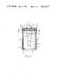
- FIG. 2 is a longitudinal sectional view taken on the line II--II of FIG. 1;
- FIG. 3 is a fragmentary sectional view taken on the line III--III of FIG. 2.
- the treatment chamber may be provided with an extractable rack, such as the one shown in the prior patent, designed to support the foodstuffs to be heat-treated.
- the rack can be introduced and removed through a front entrance which during operation is closed by a door 16.
- a sheet-metal partition 6, which may be fixedly positioned but can also be insertable and removable together with the aforementioned rack, separates the treatment chamber 2 from an air-circulation compartment surrounding it on three sides, this compartment being divided into two lateral air spaces 8', 8" and a rear air space 11 communicating freely with one another.
- Air spaces 8' and 8" are connected with chamber 2 through side apertures 9' and 9" in the lateral sections of partition 6 whose transverse rear section has a central opening 15 in line with an intake end of a radial blower 5 disposed in the rear air space 11.
- Blower 5, driven by an external electric motor 4 has a horizontal axis 0 which preferably lies at the midpoint of the rear housing wall and on which the opening 15 is centered.
- An array of peripheral blades 17 of rotor 5 generates an exiting air stream with both a radial and a tangential velocity component.
- the flow With counterclockwise rotation, as indicated by an arrow in FIG. 2, the flow will ascend and descend vertically at two horizontally offset points A and B lying on opposite sides of a vertical plane P which includes the blower axis 0.
- an upper and a lower region of rear space 11 are partly occupied by respective baffles 13 and 14 which extend across the full width of that space and form respective pairs of generally cycloidal aerodynamic deflecting surfaces 12a and 12b.
- Surfaces 12a are downwardly concave and converge at a peak 12c where they are nearly tangent to a vertical plane P' passing through point A.
- surfaces 12b are upwardly concave and converge at a peak 12d where they are nearly tangent to a vertical plane P" passing through the point B.
- Peaks 12c and 12d thus act as flow-dividing edges which respectively split the ascending and the descending air flow into components of substantially equal magnitude and uniform density passing into the lateral compartments 8' and 8".
- the two air streams thus generated pass by respective sets of heating elements in the form of upright rods 10', 10" extending over the entire effective height of air space 11 as bounded at the top and at the bottom by the deflecting surfaces 12a and 12b.
- the air discharged by blower 5 is maintained thereby at the desired food-treating temperature as it is continuously recirculated from space 11 through spaces 8' and 8" into chamber 2 and returned to the blower via opening 15.
- the side apertures 9' and 9" which may be round holes or slots, are advantageously distributed in a manner taking the progressively decreasing density of the two air streams into account--as by becoming more closely spaced or collectively wider toward the entrance door 16--in order to insure a substantially uniform heating effect throughout chamber 2.
- an inner wall surface of housing 1 has quarter-cylindrical portions C', C", with a large radius of curvature, at the junctions between its rear wall and its sidewalls, to provide a smooth transition between air spaces 11 and 8', 8".
- the aerodynamically shaped deflecting surfaces 12a and 12b which level off at the upper and lower corners of space 11, advantageously are rounded off at locations where the rear section of partition 6 deviates from them as indicated at 6' and 6". This will reduce the formation of eddies in the region where space 11 merges into spaces 8' and 8".
- both baffles may be designed as integral forward extensions of the rear housing wall and thus made of the same thermally insulating material. It is, however, also possible to make these baffles part of a sheet-metal structure integral with partition 6 and, possibly, with a food-supporting rack to be inserted into and removed from the interior of the housing as mentioned above. With such an aerodynamic structure I may therefore improve the heating efficiency of a conventional muffle oven such as that shown in the Durth patent.
- the oven according to my present invention may also be provided with adjustable vanes for controlling the air-circulation rates in accordance with the teachings of that prior patent. Even without such vanes, the oven temperature can be controlled by varying the energization of heating rods 10', 10" and/or by adjusting the blower speed within a range in which the distance of the vertical-emission points to A and B from central plane P does not change significantly. The locations of these points may be suitably preselected by the setting of blades 17 which generally will be skew to the blower axis 0.
Abstract
Description
Claims (3)
Applications Claiming Priority (2)
| Application Number | Priority Date | Filing Date | Title |
|---|---|---|---|
| DE19833306972 DE3306972A1 (en) | 1983-02-28 | 1983-02-28 | DEVICE FOR HEAT TREATMENT OF FOOD AND FOOD |
| DE3306972 | 1983-02-28 |
Publications (1)
| Publication Number | Publication Date |
|---|---|
| US4512327A true US4512327A (en) | 1985-04-23 |
Family
ID=6192044
Family Applications (1)
| Application Number | Title | Priority Date | Filing Date |
|---|---|---|---|
| US06/583,932 Expired - Fee Related US4512327A (en) | 1983-02-28 | 1984-02-27 | Muffle oven for heating foodstuffs |
Country Status (5)
| Country | Link |
|---|---|
| US (1) | US4512327A (en) |
| JP (2) | JPS59164826A (en) |
| DE (1) | DE3306972A1 (en) |
| GB (1) | GB2136110B (en) |
| NL (1) | NL189683C (en) |
Cited By (19)
| Publication number | Priority date | Publication date | Assignee | Title |
|---|---|---|---|---|
| US4707587A (en) * | 1986-01-27 | 1987-11-17 | Greenblatt Gordon M | Blood warming method and apparatus using gaseous heat exchange medium |
| US4730100A (en) * | 1986-11-26 | 1988-03-08 | Jero Manufacturing, Inc. | Food cooking and heating apparatus |
| US4742950A (en) * | 1985-03-30 | 1988-05-10 | Verwaltungsgesellschaft Heinrich Neitz GmbH & Co. KG | Method of and arrangement for soldering aluminum parts |
| US4849610A (en) * | 1988-05-31 | 1989-07-18 | Moises Alvarez | Towel warmer |
| US4924071A (en) * | 1987-07-06 | 1990-05-08 | Woodroast Systems, Inc. | Oven |
| US4954693A (en) * | 1989-07-11 | 1990-09-04 | Suga Test Instruments Co., Ltd. | Ventilation regulated hot air supplied constant temperature oven |
| US5468935A (en) * | 1994-12-10 | 1995-11-21 | Wang; Ching-Hsiang | L-electric conventional roaster oven with whirlpool air circulation |
| EP0893060A1 (en) | 1997-07-21 | 1999-01-27 | Sogerma | Oven for cooking food |
| US6069344A (en) * | 1999-01-27 | 2000-05-30 | Hp Intellectual Corp. | Convection feature for use in ovens |
| US6084214A (en) * | 1999-02-19 | 2000-07-04 | Conceptronic, Inc. | Reflow solder convection oven multi-port blower subassembly |
| US20080190299A1 (en) * | 2007-02-08 | 2008-08-14 | Daniele Turrin | Cooking oven with premix burner for boilers |
| US20090159070A1 (en) * | 2007-12-20 | 2009-06-25 | Unox S.R.L. | Muffle oven particularly for cooking food products |
| US20110247782A1 (en) * | 2010-04-09 | 2011-10-13 | Hon Hai Precision Industry Co., Ltd. | Constant temperature chamber |
| US20140083410A1 (en) * | 2011-05-31 | 2014-03-27 | BSH Bosch und Siemens Hausgeräte GmbH | Component for an appliance, arrangement with a component of this type and appliance with a corresponding arrangement |
| US20140110391A1 (en) * | 2012-10-22 | 2014-04-24 | Miguel Estrella | Oven baffle |
| US20140110392A1 (en) * | 2012-10-22 | 2014-04-24 | Miguel Estrella | Oven baffle |
| US9127888B2 (en) | 2010-07-02 | 2015-09-08 | Asc Process Systems | Industrial oven for curing composite material structures |
| KR102254654B1 (en) * | 2020-01-23 | 2021-05-21 | 김설진 | Airfryer Cooking Vessel for Food dry |
| US11076604B2 (en) | 2015-10-23 | 2021-08-03 | Duke Manufacturing Co. | Convection oven |
Families Citing this family (5)
| Publication number | Priority date | Publication date | Assignee | Title |
|---|---|---|---|---|
| BE1005701A3 (en) * | 1991-02-11 | 1993-12-21 | Atag Plan 3 B V | Convection oven. |
| WO2008080808A1 (en) * | 2006-12-29 | 2008-07-10 | Arcelik Anonim Sirketi | A cooking appliance |
| JP5197236B2 (en) * | 2008-08-28 | 2013-05-15 | 株式会社東芝 | Cooker |
| CN108903679B (en) * | 2018-08-28 | 2020-11-10 | 高孝会 | Oven with circulation heating air duct structure |
| CN116234446A (en) * | 2020-09-09 | 2023-06-06 | 布瑞威利私人有限公司 | Oven with a baking oven |
Citations (6)
| Publication number | Priority date | Publication date | Assignee | Title |
|---|---|---|---|---|
| GB631323A (en) * | 1946-09-04 | 1949-11-01 | Lyons & Co Ltd J | Improvements in and relating to ovens |
| US3719180A (en) * | 1970-02-02 | 1973-03-06 | Capic Etablissements Caillarec | Device for heat treatment by way of forced gas convection, forming a bakery, pastry, pork-butchery oven or the like |
| DE2339448A1 (en) * | 1973-08-03 | 1975-02-20 | Otto Christian Dr Med Geyer | Artificial eye ball with iris and conjunctiva-sclera - coloured photo-images of natural eye-parts being used for imitation |
| DE2557867A1 (en) * | 1975-12-22 | 1977-06-30 | Bosch Siemens Hausgeraete | Air circulating oven for baking and roasting - has fan to create turbulence with zoned heating through partition slots |
| GB2109920A (en) * | 1981-10-02 | 1983-06-08 | Victoria Gas & Fuel Corp | Forced draught ovens |
| EP0094816A2 (en) * | 1982-05-19 | 1983-11-23 | Mastermatic Inc. | Apparatus and method for heating food products |
Family Cites Families (7)
| Publication number | Priority date | Publication date | Assignee | Title |
|---|---|---|---|---|
| FR953836A (en) * | 1946-09-04 | 1949-12-14 | Lyons & Co Ltd J | Improvements in ovens |
| DE1977158U (en) * | 1967-10-11 | 1968-01-18 | Burger Eisenwerke Ag | APPLIANCE FOR PREPARING FOOD. |
| DE2339446C3 (en) * | 1973-08-03 | 1978-03-02 | Bosch-Siemens Hausgeraete Gmbh, 7000 Stuttgart | Convection oven for cooking food |
| JPS5132868U (en) * | 1974-09-03 | 1976-03-10 | ||
| JPS5340828A (en) * | 1976-09-25 | 1978-04-13 | Toshiba Ray O Vac | Method of producing battery |
| DE2950946C2 (en) * | 1979-12-18 | 1984-08-09 | Bosch-Siemens Hausgeräte GmbH, 7000 Stuttgart | Oven with fan and grill element |
| NL8003693A (en) * | 1980-06-26 | 1982-01-18 | Inventum Koninklijke Fab | OVEN FOR HEATING FOOD IN TRAYS. |
-
1983
- 1983-02-28 DE DE19833306972 patent/DE3306972A1/en active Granted
-
1984
- 1984-01-30 NL NLAANVRAGE8400277,A patent/NL189683C/en not_active IP Right Cessation
- 1984-02-06 GB GB08403091A patent/GB2136110B/en not_active Expired
- 1984-02-27 US US06/583,932 patent/US4512327A/en not_active Expired - Fee Related
- 1984-02-27 JP JP59034503A patent/JPS59164826A/en active Pending
-
1992
- 1992-08-05 JP JP054983U patent/JPH0622802U/en active Pending
Patent Citations (6)
| Publication number | Priority date | Publication date | Assignee | Title |
|---|---|---|---|---|
| GB631323A (en) * | 1946-09-04 | 1949-11-01 | Lyons & Co Ltd J | Improvements in and relating to ovens |
| US3719180A (en) * | 1970-02-02 | 1973-03-06 | Capic Etablissements Caillarec | Device for heat treatment by way of forced gas convection, forming a bakery, pastry, pork-butchery oven or the like |
| DE2339448A1 (en) * | 1973-08-03 | 1975-02-20 | Otto Christian Dr Med Geyer | Artificial eye ball with iris and conjunctiva-sclera - coloured photo-images of natural eye-parts being used for imitation |
| DE2557867A1 (en) * | 1975-12-22 | 1977-06-30 | Bosch Siemens Hausgeraete | Air circulating oven for baking and roasting - has fan to create turbulence with zoned heating through partition slots |
| GB2109920A (en) * | 1981-10-02 | 1983-06-08 | Victoria Gas & Fuel Corp | Forced draught ovens |
| EP0094816A2 (en) * | 1982-05-19 | 1983-11-23 | Mastermatic Inc. | Apparatus and method for heating food products |
Cited By (20)
| Publication number | Priority date | Publication date | Assignee | Title |
|---|---|---|---|---|
| US4742950A (en) * | 1985-03-30 | 1988-05-10 | Verwaltungsgesellschaft Heinrich Neitz GmbH & Co. KG | Method of and arrangement for soldering aluminum parts |
| US4707587A (en) * | 1986-01-27 | 1987-11-17 | Greenblatt Gordon M | Blood warming method and apparatus using gaseous heat exchange medium |
| US4730100A (en) * | 1986-11-26 | 1988-03-08 | Jero Manufacturing, Inc. | Food cooking and heating apparatus |
| US4924071A (en) * | 1987-07-06 | 1990-05-08 | Woodroast Systems, Inc. | Oven |
| US4849610A (en) * | 1988-05-31 | 1989-07-18 | Moises Alvarez | Towel warmer |
| US4954693A (en) * | 1989-07-11 | 1990-09-04 | Suga Test Instruments Co., Ltd. | Ventilation regulated hot air supplied constant temperature oven |
| US5468935A (en) * | 1994-12-10 | 1995-11-21 | Wang; Ching-Hsiang | L-electric conventional roaster oven with whirlpool air circulation |
| EP0893060A1 (en) | 1997-07-21 | 1999-01-27 | Sogerma | Oven for cooking food |
| US6069344A (en) * | 1999-01-27 | 2000-05-30 | Hp Intellectual Corp. | Convection feature for use in ovens |
| US6084214A (en) * | 1999-02-19 | 2000-07-04 | Conceptronic, Inc. | Reflow solder convection oven multi-port blower subassembly |
| US20080190299A1 (en) * | 2007-02-08 | 2008-08-14 | Daniele Turrin | Cooking oven with premix burner for boilers |
| US8146488B2 (en) * | 2007-02-08 | 2012-04-03 | Electrolux Professional Spa | Cooking oven with premix burner for boilers |
| US20090159070A1 (en) * | 2007-12-20 | 2009-06-25 | Unox S.R.L. | Muffle oven particularly for cooking food products |
| US20110247782A1 (en) * | 2010-04-09 | 2011-10-13 | Hon Hai Precision Industry Co., Ltd. | Constant temperature chamber |
| US9127888B2 (en) | 2010-07-02 | 2015-09-08 | Asc Process Systems | Industrial oven for curing composite material structures |
| US20140083410A1 (en) * | 2011-05-31 | 2014-03-27 | BSH Bosch und Siemens Hausgeräte GmbH | Component for an appliance, arrangement with a component of this type and appliance with a corresponding arrangement |
| US20140110391A1 (en) * | 2012-10-22 | 2014-04-24 | Miguel Estrella | Oven baffle |
| US20140110392A1 (en) * | 2012-10-22 | 2014-04-24 | Miguel Estrella | Oven baffle |
| US11076604B2 (en) | 2015-10-23 | 2021-08-03 | Duke Manufacturing Co. | Convection oven |
| KR102254654B1 (en) * | 2020-01-23 | 2021-05-21 | 김설진 | Airfryer Cooking Vessel for Food dry |
Also Published As
| Publication number | Publication date |
|---|---|
| JPS59164826A (en) | 1984-09-18 |
| NL189683B (en) | 1993-01-18 |
| NL8400277A (en) | 1984-09-17 |
| NL189683C (en) | 1993-06-16 |
| JPH0622802U (en) | 1994-03-25 |
| GB8403091D0 (en) | 1984-03-07 |
| GB2136110B (en) | 1986-10-15 |
| DE3306972C2 (en) | 1987-01-22 |
| DE3306972A1 (en) | 1984-10-04 |
| GB2136110A (en) | 1984-09-12 |
Similar Documents
| Publication | Publication Date | Title |
|---|---|---|
| US4512327A (en) | Muffle oven for heating foodstuffs | |
| US3828760A (en) | Oven | |
| US5601070A (en) | Convection oven | |
| US4591333A (en) | Impingement oven with radiant panel | |
| US5205274A (en) | Turntable convection oven | |
| US5423248A (en) | Air circulator for impingement heat transfer apparatus | |
| US4928663A (en) | Enhanced air-flow convection oven | |
| CA1166105A (en) | Dual flow heating apparatus | |
| US5816234A (en) | Convection oven | |
| US5398666A (en) | Turntable convection heater | |
| EP2636955B1 (en) | A cooking oven provided for heat transfer by convection | |
| US5671660A (en) | Heated air-circulating oven | |
| US20190298106A1 (en) | An air-based cooker | |
| US4981416A (en) | Enhanced air-flow blower wheel | |
| US5584237A (en) | Heated air-circulating oven | |
| MXPA04008964A (en) | Convection oven and related air flow system. | |
| US5165889A (en) | Gas convection oven with heat exchanger and baffles | |
| CN113251449B (en) | Cooking apparatus | |
| EP1478888B1 (en) | Oven with forced air circulation | |
| US6069344A (en) | Convection feature for use in ovens | |
| US3118436A (en) | Oven construction | |
| EP3348914B1 (en) | Oven for cooking foods | |
| CN113143053A (en) | Cooking apparatus | |
| EP0611524A1 (en) | Forced convection cooking oven | |
| US3074393A (en) | High velocity oven |
Legal Events
| Date | Code | Title | Description |
|---|---|---|---|
| AS | Assignment |
Owner name: BUDERUS AKTIENGESELLSCHAFT, D-6330 WETZLAR, W. GER Free format text: ASSIGNMENT OF ASSIGNORS INTEREST.;ASSIGNOR:STIEGLER, HARTMUT;REEL/FRAME:004236/0109 Effective date: 19840110 |
|
| FEPP | Fee payment procedure |
Free format text: PAYOR NUMBER ASSIGNED (ORIGINAL EVENT CODE: ASPN); ENTITY STATUS OF PATENT OWNER: LARGE ENTITY |
|
| AS | Assignment |
Owner name: BUDERUS SELL GMBH, D-6348 HERBORN/HESSEN, WEST GER Free format text: ASSIGNMENT OF ASSIGNORS INTEREST.;ASSIGNOR:BUDERUS, AKTIENGESELLSCHAFT;REEL/FRAME:004824/0178 Effective date: 19870107 Owner name: BUDERUS SELL GMBH, A JOING STOCK COMPANY WITH LIMI Free format text: ASSIGNMENT OF ASSIGNORS INTEREST;ASSIGNOR:BUDERUS, AKTIENGESELLSCHAFT;REEL/FRAME:004824/0178 Effective date: 19870107 |
|
| FPAY | Fee payment |
Year of fee payment: 4 |
|
| FPAY | Fee payment |
Year of fee payment: 8 |
|
| REMI | Maintenance fee reminder mailed | ||
| LAPS | Lapse for failure to pay maintenance fees | ||
| FP | Lapsed due to failure to pay maintenance fee |
Effective date: 19970423 |
|
| STCH | Information on status: patent discontinuation |
Free format text: PATENT EXPIRED DUE TO NONPAYMENT OF MAINTENANCE FEES UNDER 37 CFR 1.362 |