US4507590A - Brushless DC motor - Google Patents
Brushless DC motor Download PDFInfo
- Publication number
- US4507590A US4507590A US06/514,133 US51413383A US4507590A US 4507590 A US4507590 A US 4507590A US 51413383 A US51413383 A US 51413383A US 4507590 A US4507590 A US 4507590A
- Authority
- US
- United States
- Prior art keywords
- brushless
- motor
- signals
- digital
- bit parallel
- Prior art date
- Legal status (The legal status is an assumption and is not a legal conclusion. Google has not performed a legal analysis and makes no representation as to the accuracy of the status listed.)
- Expired - Fee Related
Links
- 230000001351 cycling effect Effects 0.000 claims 1
- 238000006243 chemical reaction Methods 0.000 description 6
- 238000001514 detection method Methods 0.000 description 4
- 238000010586 diagram Methods 0.000 description 4
- 238000000034 method Methods 0.000 description 3
- 230000035945 sensitivity Effects 0.000 description 3
- 230000003111 delayed effect Effects 0.000 description 2
- 230000003247 decreasing effect Effects 0.000 description 1
- 230000010354 integration Effects 0.000 description 1
- 230000004048 modification Effects 0.000 description 1
- 238000012986 modification Methods 0.000 description 1
- 230000003287 optical effect Effects 0.000 description 1
- 230000000630 rising effect Effects 0.000 description 1
Images

Classifications
-
- H—ELECTRICITY
- H02—GENERATION; CONVERSION OR DISTRIBUTION OF ELECTRIC POWER
- H02P—CONTROL OR REGULATION OF ELECTRIC MOTORS, ELECTRIC GENERATORS OR DYNAMO-ELECTRIC CONVERTERS; CONTROLLING TRANSFORMERS, REACTORS OR CHOKE COILS
- H02P6/00—Arrangements for controlling synchronous motors or other dynamo-electric motors using electronic commutation dependent on the rotor position; Electronic commutators therefor
- H02P6/14—Electronic commutators
- H02P6/16—Circuit arrangements for detecting position
Definitions
- a conventional brushless DC motor includes: a stator on which drive coils are mounted, a magnetic rotor assembly having magnetic poles arranged alternately in the circumferential direction, a position detector for detecting the position of the rotor relative to the stator, and a drive circuit for applying current to the drive coils according to the detection signal of the position detector.
- a rotary encoder coupled to the magnetic rotor is employed as the position detector. Application of current to the drive coils is controlled according to the output signal of the rotary encoder.
- the conventional brushless DC motor suffers from the following difficulties: In the case of two-phase drive coils, it is necessary to provide two position detectors for detection of the rotor position, in the case of three-phase drive coils, it is necessary to provide three position detectors, etc. That is, the motor requires a plurality of position detectors, and thus is intricate in its physical and electrical arrangement.
- the position detection signals are, in general, converted into switching waveforms which are applied to the drive coils without modification.
- the output torque characteristic of the motor includes harmonic components, which makes the motor vibrate and produce noise.
- An object of the invention is therefore to provide a brushless DC motor which has a simplified arrangement, in which only one position detector is used, and which is so designed as to provide coil driving signals having a high waveform accuracy, thus providing a uniform output torque characteristic such that no vibration is generated.
- the invention provides a brushless DC motor including n phase drive coils mounted fixedly on a stator yoke, a magnetic rotor assembly positioned to be rotated by the drive coils, a rotary encoder coupled to the magnetic rotor assembly to be rotated thereby with m tracks of digitally coded waveform data being recorded on the rotary encoder, a stationary m-channel detecting element for detecting the waveform data produced by rotating the rotary encoder to thereby provide an m-bit parallel signal, a code converter circuit for converting the m-bit parallel signal from the detecting element to thereby form n phase drive signals, and n power amplifiers for amplifying the n phase drive signals from the converter circuit to apply in response thereto currents to the drive coils.
- the code converter circuit can be implemented simply by appropriately delaying the m-bit parallel signal for all but one of the power amplifiers.
- the code converter circuit can be further implemented with digital-to-analog converters receiving an undelayed and delayed versions of the m-bit parallel signal.
- the code converter circuit can be implemented with down counters which are preset with the undelayed and delayed versions of the m-bit parallel signal.
- FIG. 1 is a block diagram of a first embodiment of a brushless DC motor of the invention
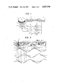
- FIG. 2 is an explanatory diagram showing an example of code conversion used in the embodiment of FIG. 1;
- FIG. 3 is a block diagram of a second embodiment of a brushless DC motor of the invention.
- FIG. 4 is an explanatory diagram showing an example of code conversion used in the second embodiment of FIG. 3.
- FIGS. 5A and 5B are timing charts for a description of the operation of a pulse width modulator section used in the second embodiment.
- a position detecting rotor 1 (illustrated schematically) is coupled through a shaft 11 to a rotor 12.
- the rotor 12 has a magnetic rotor assembly 2 made up of N (north) and S (south) poles which are arranged alternately in the circumferential direction as shown unfolded in FIG. 2 (indicated also by reference numeral 2).
- the rotor assembly 2 is rotated when three-phase drive coils C 1 , C 2 and C 3 , which are star-connected, are energized through a drive circuit (described below).
- Four-bit patterns D 0 , D 1 , D 2 and D 3 as shown in FIG. 2 are formed on the cylindrical wall of the position detecting rotor 1.
- bit patterns are read, one bit from each pattern at a time, by a four-channel position detector 3 which is fixedly provided on the stator side.
- the bit patterns and the position detector 3 may be replaced by a magnetic track and a magnetic head, or by an optical pattern and light emitting and receiving elements, or by any other suitable equivalent arrangement.
- the number of bits may be increased or decreased depending on the intended use of the motor.
- the four-bit digital signal detected by the position detector 3, which forms a position signal is applied to a code converter 4 to provide digital phase signals U, V and W, which are signals shifted about 2 ⁇ /3 in phase from one another, in response to the position signal from the position detector 3 which changes cyclically as the position detecting rotor 1 turns. This can be done merely by appropriately delaying the V and W output signals relative to the U output signal.
- the output signals for the three phases are applied to D/A (digital-to-analog) converters 5, 6 and 7.
- the outputs of the D/A converters 5, 6 and 7 are applied to the three-phase coils C 1 , C 2 and C 3 , after being amplified by amplifiers 8, 9 and 10, respectively.
- the position detector 3 detects the bit patterns on the wall of the rotor 1 and produces in response thereto a four-bit digital signal.
- This signal is a digital signal, the period of which corresponds to 16 cells, as is clear from the bit pattern in FIG. 2.
- the code converter 4 applies the digital signal from the detector 3 directly to the U-phase D/A converter 5, and also converts the digital signal into digital signals which are shifted by approximately 2 ⁇ /3 in phase from each other, and applies the latter to the V-phase D/A converter 6 and to the W-phase D/A converter 7, respectively. Table 1 below shows one example of such code conversion by the code converter 4.
- the digital signals thus code converted for the three phases are converted into analog signals by the D/A converters 5, 6 and 7, respectively.
- the analog signals are substantially in the form of a sine wave as shown in FIG. 2 wherein they are indicated by U, V and W, respectively. It is apparent from FIG. 2 that these analog signals are shifted approximately 2 ⁇ /3 in phase from one another. Therefore, when these analog signals are applied to the three-phase coils C 1 , C 2 and C 3 through the amplifiers 8, 9 and 10, respectively, a rotating magnetic field is induced in a predetermined direction, so that the magnetic rotor assembly is rotated together with the rotors 1 and 12 in synchronization therewith.
- the direction of rotation can be reversed by shifting the conversion codes for the U, V and W phases by 180° in electrical angle. In this case, the phases are shifted in the opposite direction so that the direction of the rotating magnetic field is reversed.
- one or more additional bit patterns can be added on the rotor 1, and detected for use as a speed control signal. Moreover, control can be effected with the D 0 bit as the speed control signal and with the D 3 bit as a phase control signal. Employment of the D 0 , D 1 , D 2 and D 3 bits as speed control signals permits proportional speed controls.
- the position detection signal outputted by the position detector may not be suitable for the D/A converters if not processed.
- the code converter 4 can be used to make the signal suitable for use by the D/A converters.
- FIG. 3 Another embodiment of the invention will be described with reference to FIG. 3.
- the arrangement of the position detecting rotor 1, rotor 12, magnetic rotor assembly 2, position detector 3 and code converter 4 is the same as that of those in the first embodiment of FIG. 1.
- the second embodiment differs though from the first embodiment in that the drive coils C 1 , C 2 and C 3 are driven using a PWM (Pulse Width Modulation) technique.
- PWM Pulse Width Modulation
- bits D 0 through D 2 , D 0 ' through D 2 ' and D 0 " through D 2 ", respectively, are applied to the preset input ports of down counters 15, 16 and 17, respectively.
- Bits D 3 , D 3 ' and D 3 " are applied as current direction switching signals to a U-phase current direction switching circuit including AND gates 21 and 22 and an inverter, a V-phase current direction switching circuit including AND gates 23 and 24 and an inverter, and a W-phase current direction switching circuit including AND gates 25 and 26 and an inverter.
- a pulse oscillator 18 applies a clock pulse signal to the clock input terminals T of the counters 15, 16 and 17.
- the clock pulse signal is further applied to a down counter 19.
- the down counter 19 counts downwardly in response to the clock pulse signal to thus provide a load signal which is applied to the preset signal terminals of the counters 15, 16 and 17.
- the output of the counter 15 is applied to the U-phase current direction switching circuit including the AND gates 21 and 22.
- the output of the counter 16 is applied to the V-phase current direction switching circuit including the AND gates 23 and 24.
- the output of the counter 17 is applied to the W-phase current direction switching circuit including the AND gates 25 and 26.
- the outputs of the AND gates 21, 22, 23, 24, 25 and 26 are applied to switching transistors 31, 32, 33, 34, 35 and 36, respectively.
- the position detector 3 reads the waveform data of the rotor 1 which has been digitally coded and recorded.
- the code converter 4 converts the output signal from the detector 3 into digital code signals for the U, V and W phases.
- three bits D 0 through D 2 three bits D 0 ' through D 2 ' and three bits D 0 " through D 2 " are applied, as preset signals, to the down counters 15, 16 and 17, respectively, and the remaining bits D 3 , D 3 ' and D 3 " are applied to the current direction switching circuits for the U, V and W phases, respectively.
- the down counter 19 counts down the clock pulse signal from the oscillator 18 to produce a load signal having a period T c , as shown in FIG. 5A, which is applied to the preset signal (load) input terminals of the counters 15, 16 and 17.
- Each of the counters 15, 16 and 17 outputs an "H" (high) level signal upon being reset at the rising edge of the load signal (see FIG. 5B), and starts counting downwardly in response to the output signal from the oscillator 18.
- the count value of each counter reaches zero and the output is at the "L" (low) level
- the counting operation is stopped.
- the counters 15, 16 and 17 start their counting operations again.
- bits D 3 , D 3 ' and D 3 " are applied as current direction switching signals to the current switching circuits for the respective three phases. Therefore, the directions of the coil currents are changed in synchronization with the pulse width variation period.
- currents are applied to the coils C 1 , C 2 and C 3 alternately in the forward and reverse directions according to the pulse-width-modulated signals for the three phases.
- the amount of current applied to each coil corresponds to the integration period of the respective pulse-width-modulated signal. That is, a current which is substantially in the form of a sine wave is applied to each coil.
- the currents applied to the coils are shifted by about 2 ⁇ /3 from one another by the code converter 4. Therefore, the rotor is rotated in the second embodiment in the same manner as in the first embodiment.
- the output duty cycle and the position of the bit pattern of the rotor depend on the code conversion method employed. Accordingly, the bit pattern and the code conversion method should be suitably selected in designing the DC brushless motor.
- the brushless DC motor of the invention has a simple physical and electrical arrangement, and is free from the drawbacks which arise when a plurality of position detectors are employed, that is, drawbacks such as fluctuations in the sensitivity of the position detectors.
- the motor of the invention will rotate smoothly at all times.
- each drive coil is driven by a signal which is substantially in the form of a sine wave, vibration and variations in output torque are eliminated in the brushless DC motor of the invention.
- the number of phases of drive coils and the number of bits of the waveform data recorded in the rotor may be varied as desired.
Landscapes
- Engineering & Computer Science (AREA)
- Power Engineering (AREA)
- Control Of Motors That Do Not Use Commutators (AREA)
- Brushless Motors (AREA)
Abstract
Description
                                  TABLE 1
__________________________________________________________________________
1    2 3 4 5 6 7 8 9 10 11 12 13 14 15 16
__________________________________________________________________________
D.sub.0
   0 1 0 1 0 1 0 1 0 1  0  1  0  1  0  1
D.sub.1
   0 0 1 1 0 0 1 1 0 0  1  1  0  0  1  1
D.sub.2
   0 0 0 0 1 1 1 1 0 0  0  0  1  1  1  1
D.sub.3
   0 0 0 0 0 0 0 0 1 1  1  1  1  1  1  1
V
D.sub.0 '
   1 0 1 0 1 0 1 0 1 0  1  0  1  0  1  0
D.sub.1 '
   1 0 0 1 1 0 0 1 1 0  0  1  1  0  0  1
D.sub.2 '
   0 1 1 1 1 0 0 0 0 1  1  1  1  0  0  0
D.sub.3 '
   1 1 1 1 1 0 0 0 0 0  0  0  0  1  1  1
W
D.sub.0 "
   1 0 1 0 1 0 1 0 1 0  1  0  1  0  1  0
D.sub.1 "
   0 1 1 0 0 1 1 0 0 1  1  0  0  1  1  0
D.sub.2 "
   1 1 1 0 0 0 0 1 1 1  1  0  0  0  0  1
D.sub.3 "
   0 0 0 1 1 1 1 1 1 1  1  0  0  0  0  0
__________________________________________________________________________
Claims (8)
Applications Claiming Priority (2)
| Application Number | Priority Date | Filing Date | Title |
|---|---|---|---|
| JP57-123213 | 1982-07-15 | ||
| JP57123213A JPH0632582B2 (en) | 1982-07-15 | 1982-07-15 | DC brushless electric motor |
Publications (1)
| Publication Number | Publication Date |
|---|---|
| US4507590A true US4507590A (en) | 1985-03-26 |
Family
ID=14854995
Family Applications (1)
| Application Number | Title | Priority Date | Filing Date |
|---|---|---|---|
| US06/514,133 Expired - Fee Related US4507590A (en) | 1982-07-15 | 1983-07-15 | Brushless DC motor |
Country Status (3)
| Country | Link |
|---|---|
| US (1) | US4507590A (en) |
| JP (1) | JPH0632582B2 (en) |
| DE (1) | DE3325610A1 (en) |
Cited By (24)
| Publication number | Priority date | Publication date | Assignee | Title |
|---|---|---|---|---|
| US4689532A (en) * | 1985-05-07 | 1987-08-25 | Howlett James F | Ferritic sensor, self-controlled synchronous motor |
| US4827203A (en) * | 1986-03-14 | 1989-05-02 | Fanuc Ltd | Rotor rotational position detector for a motor |
| US4849680A (en) * | 1986-11-07 | 1989-07-18 | Kabushiki Kaisha Empire Airport Service | Encoder |
| US4870332A (en) * | 1988-07-08 | 1989-09-26 | Xebec | Voltage-boosting motor controller |
| US4879502A (en) * | 1985-01-28 | 1989-11-07 | Hitachi, Ltd. | Speed control apparatus and method for motors |
| US4899093A (en) * | 1986-09-05 | 1990-02-06 | Deutsche-Thomson Brandt Gmbh | Circuitry for electronically commutating a direct-current motor |
| EP0324396A3 (en) * | 1988-01-15 | 1990-02-14 | Deutsche Thomson-Brandt GmbH | Method to commutate the coil strand of a dc motor |
| US4947071A (en) * | 1987-02-02 | 1990-08-07 | Craig Clarke | High speed DC motor |
| US4959599A (en) * | 1985-05-22 | 1990-09-25 | Fuji Photo Film Co., Ltd. | Head positioner |
| US5004965A (en) * | 1987-05-20 | 1991-04-02 | Canon Kabushiki Kaisha | Brushless motor with torque compensation |
| US5013988A (en) * | 1987-10-29 | 1991-05-07 | Fanuc Ltd | Absolute position encoder |
| EP0377835A3 (en) * | 1989-01-10 | 1991-05-08 | Heidelberger Druckmaschinen Aktiengesellschaft | Device for detecting the rotor position and rotation speed of an electric motor |
| WO1993023911A1 (en) * | 1992-05-15 | 1993-11-25 | Deutsche Thomson-Brandt Gmbh | Process and device for motor control |
| US5361021A (en) * | 1990-03-22 | 1994-11-01 | Heidelberger Druckmaschinen Ag | Method for suppressing current peaks during commutation of a brushless direct-current motor |
| US5397971A (en) * | 1992-06-08 | 1995-03-14 | Hewlett-Packard Company | Bi-polar disk torquing system for a disk drive to free stuck transducers |
| US5539293A (en) * | 1993-06-07 | 1996-07-23 | Switched Reluctance Drives Limited | Rotor position encoder having features in decodable angular positions |
| US5650779A (en) * | 1995-03-28 | 1997-07-22 | Switched Reluctance Drives, Ltd. | Position encoder |
| US5723858A (en) * | 1995-03-28 | 1998-03-03 | Switched Reluctance Drives, Ltd. | Position encoder with fault indicator |
| US5973461A (en) * | 1996-09-27 | 1999-10-26 | Valeo Electronique | Method and device for starting and synchronizing a three-phase motor |
| US6051943A (en) * | 1994-03-03 | 2000-04-18 | Iomega Corporation | Servo motor controller using position interpolation |
| US6384554B1 (en) | 1991-10-03 | 2002-05-07 | Papst Licensing Gmbh | Drive circuit for brushless DC motors |
| US20050077860A1 (en) * | 2002-06-14 | 2005-04-14 | Hagen Mark D. | Resonant scanning mirror driver circuit |
| US20090102461A1 (en) * | 2007-10-22 | 2009-04-23 | The Timken Company | Absolute position magnetic encoder with binary and decimal output |
| CN110474575A (en) * | 2018-05-11 | 2019-11-19 | 士林电机厂股份有限公司 | Brushless motor torsion position encoder device |
Families Citing this family (1)
| Publication number | Priority date | Publication date | Assignee | Title |
|---|---|---|---|---|
| DE4036024C1 (en) * | 1990-11-13 | 1992-02-27 | Heidelberger Druckmaschinen Ag, 6900 Heidelberg, De |
Citations (9)
| Publication number | Priority date | Publication date | Assignee | Title |
|---|---|---|---|---|
| US3324369A (en) * | 1964-10-06 | 1967-06-06 | Ampex | Control system for incremental motors having winding condition sensing including photocells |
| US3345547A (en) * | 1965-01-21 | 1967-10-03 | Ampex | Step motor control system including a three stage energization for each step |
| US3378741A (en) * | 1964-09-18 | 1968-04-16 | Ibm | Digital coarse and fine stepping motor control using an encoder for coarse position |
| US3753067A (en) * | 1972-05-17 | 1973-08-14 | Peripheral Systems Corp | Motor speed regulation system |
| US3766458A (en) * | 1970-12-28 | 1973-10-16 | Fujitsu Ltd | System for driving a self-excited pulse motor in accordance with the movement of the rotor |
| US4107594A (en) * | 1977-01-24 | 1978-08-15 | Teletype Corporation | Step motor velocity control |
| US4223261A (en) * | 1978-08-23 | 1980-09-16 | Exxon Research & Engineering Co. | Multi-phase synchronous machine system |
| JPS5674094A (en) * | 1979-11-22 | 1981-06-19 | Sony Corp | Brushless dc motor |
| JPS5791683A (en) * | 1980-11-28 | 1982-06-07 | Hitachi Ltd | Control circuit of dc brushless motor |
Family Cites Families (1)
| Publication number | Priority date | Publication date | Assignee | Title |
|---|---|---|---|---|
| JPS5622694U (en) * | 1979-07-28 | 1981-02-28 |
-
1982
- 1982-07-15 JP JP57123213A patent/JPH0632582B2/en not_active Expired - Lifetime
-
1983
- 1983-07-15 DE DE19833325610 patent/DE3325610A1/en not_active Withdrawn
- 1983-07-15 US US06/514,133 patent/US4507590A/en not_active Expired - Fee Related
Patent Citations (9)
| Publication number | Priority date | Publication date | Assignee | Title |
|---|---|---|---|---|
| US3378741A (en) * | 1964-09-18 | 1968-04-16 | Ibm | Digital coarse and fine stepping motor control using an encoder for coarse position |
| US3324369A (en) * | 1964-10-06 | 1967-06-06 | Ampex | Control system for incremental motors having winding condition sensing including photocells |
| US3345547A (en) * | 1965-01-21 | 1967-10-03 | Ampex | Step motor control system including a three stage energization for each step |
| US3766458A (en) * | 1970-12-28 | 1973-10-16 | Fujitsu Ltd | System for driving a self-excited pulse motor in accordance with the movement of the rotor |
| US3753067A (en) * | 1972-05-17 | 1973-08-14 | Peripheral Systems Corp | Motor speed regulation system |
| US4107594A (en) * | 1977-01-24 | 1978-08-15 | Teletype Corporation | Step motor velocity control |
| US4223261A (en) * | 1978-08-23 | 1980-09-16 | Exxon Research & Engineering Co. | Multi-phase synchronous machine system |
| JPS5674094A (en) * | 1979-11-22 | 1981-06-19 | Sony Corp | Brushless dc motor |
| JPS5791683A (en) * | 1980-11-28 | 1982-06-07 | Hitachi Ltd | Control circuit of dc brushless motor |
Cited By (30)
| Publication number | Priority date | Publication date | Assignee | Title |
|---|---|---|---|---|
| US4879502A (en) * | 1985-01-28 | 1989-11-07 | Hitachi, Ltd. | Speed control apparatus and method for motors |
| US4689532A (en) * | 1985-05-07 | 1987-08-25 | Howlett James F | Ferritic sensor, self-controlled synchronous motor |
| US4959599A (en) * | 1985-05-22 | 1990-09-25 | Fuji Photo Film Co., Ltd. | Head positioner |
| US4827203A (en) * | 1986-03-14 | 1989-05-02 | Fanuc Ltd | Rotor rotational position detector for a motor |
| US4899093A (en) * | 1986-09-05 | 1990-02-06 | Deutsche-Thomson Brandt Gmbh | Circuitry for electronically commutating a direct-current motor |
| US4849680A (en) * | 1986-11-07 | 1989-07-18 | Kabushiki Kaisha Empire Airport Service | Encoder |
| US4947071A (en) * | 1987-02-02 | 1990-08-07 | Craig Clarke | High speed DC motor |
| US5004965A (en) * | 1987-05-20 | 1991-04-02 | Canon Kabushiki Kaisha | Brushless motor with torque compensation |
| US5013988A (en) * | 1987-10-29 | 1991-05-07 | Fanuc Ltd | Absolute position encoder |
| EP0324396A3 (en) * | 1988-01-15 | 1990-02-14 | Deutsche Thomson-Brandt GmbH | Method to commutate the coil strand of a dc motor |
| US4870332A (en) * | 1988-07-08 | 1989-09-26 | Xebec | Voltage-boosting motor controller |
| EP0377835A3 (en) * | 1989-01-10 | 1991-05-08 | Heidelberger Druckmaschinen Aktiengesellschaft | Device for detecting the rotor position and rotation speed of an electric motor |
| US5361021A (en) * | 1990-03-22 | 1994-11-01 | Heidelberger Druckmaschinen Ag | Method for suppressing current peaks during commutation of a brushless direct-current motor |
| US6384554B1 (en) | 1991-10-03 | 2002-05-07 | Papst Licensing Gmbh | Drive circuit for brushless DC motors |
| US7067998B2 (en) * | 1991-10-03 | 2006-06-27 | Papst Licensing Gmbh & Co. Kg | Drive circuit for brushless DC motors |
| US20040239274A1 (en) * | 1991-10-03 | 2004-12-02 | Papst Licensing Gmbh | Drive circuit for brushless DC motors |
| US20020093300A1 (en) * | 1991-10-03 | 2002-07-18 | Papst Licensing Gmbh | Drive circuit for brushless DC motors |
| WO1993023911A1 (en) * | 1992-05-15 | 1993-11-25 | Deutsche Thomson-Brandt Gmbh | Process and device for motor control |
| US5397971A (en) * | 1992-06-08 | 1995-03-14 | Hewlett-Packard Company | Bi-polar disk torquing system for a disk drive to free stuck transducers |
| US5539293A (en) * | 1993-06-07 | 1996-07-23 | Switched Reluctance Drives Limited | Rotor position encoder having features in decodable angular positions |
| US5637972A (en) * | 1993-06-07 | 1997-06-10 | Switched Reluctance Drives, Ltd. | Rotor position encoder having features in decodeable angular positions |
| US6051943A (en) * | 1994-03-03 | 2000-04-18 | Iomega Corporation | Servo motor controller using position interpolation |
| US5650779A (en) * | 1995-03-28 | 1997-07-22 | Switched Reluctance Drives, Ltd. | Position encoder |
| US5723858A (en) * | 1995-03-28 | 1998-03-03 | Switched Reluctance Drives, Ltd. | Position encoder with fault indicator |
| US5973461A (en) * | 1996-09-27 | 1999-10-26 | Valeo Electronique | Method and device for starting and synchronizing a three-phase motor |
| US20050077860A1 (en) * | 2002-06-14 | 2005-04-14 | Hagen Mark D. | Resonant scanning mirror driver circuit |
| US6956350B2 (en) * | 2002-06-14 | 2005-10-18 | Texas Instruments Incorporated | Resonant scanning mirror driver circuit |
| US20090102461A1 (en) * | 2007-10-22 | 2009-04-23 | The Timken Company | Absolute position magnetic encoder with binary and decimal output |
| US7999536B2 (en) * | 2007-10-22 | 2011-08-16 | The Timken Company | Absolute position magnetic encoder with binary and decimal output |
| CN110474575A (en) * | 2018-05-11 | 2019-11-19 | 士林电机厂股份有限公司 | Brushless motor torsion position encoder device |
Also Published As
| Publication number | Publication date |
|---|---|
| JPS5914388A (en) | 1984-01-25 |
| JPH0632582B2 (en) | 1994-04-27 |
| DE3325610A1 (en) | 1984-01-19 |
Similar Documents
| Publication | Publication Date | Title |
|---|---|---|
| US4507590A (en) | Brushless DC motor | |
| US4874993A (en) | Sensorless brushless motor | |
| US5408153A (en) | Index position detecting apparatus for an electromagnetic rotary machine | |
| US5072166A (en) | Position sensor elimination technique for the switched reluctance motor drive | |
| JP3325997B2 (en) | Motor control device and control method | |
| US4717864A (en) | Speed control method and apparatus for electronically commutated motors | |
| US6925412B2 (en) | Method for adjusting a sensor device for determining the rotational position of an electronically-commutated motor rotor | |
| JP2001045788A (en) | Brushless motor and its rotary control method | |
| KR19980024150A (en) | Driving Circuit of Three-Phase Bildish Motor Using 1-Hole Signal | |
| KR100441319B1 (en) | Rotor position encoder for an electrical machine | |
| JPH10229691A (en) | Speed controller of motor | |
| JPH1075594A (en) | Drive controller for brushless motor | |
| JP4269246B2 (en) | Encoder and motor with encoder | |
| JP2022032111A (en) | Brushless motor drive device, brushless motor drive system and brushless motor drive method | |
| JP3310045B2 (en) | Sine-wave drive current generator for AC servomotor | |
| JPH0614580A (en) | Motor controller | |
| JPS6387189A (en) | Driving circuit for brushless motor | |
| JPH05122983A (en) | Permanent magnet motor controller | |
| JPH0564558B2 (en) | ||
| JPH0297294A (en) | DC motor rotation speed detection device | |
| JP2934257B2 (en) | Servo device | |
| EP0424467A1 (en) | Motor drive system | |
| JPH0591706A (en) | Electromagnetic rotating machine | |
| JP2001008485A (en) | Pwm output device for driving three-phase brushless motor | |
| JP2002323911A (en) | Sequence controller |
Legal Events
| Date | Code | Title | Description |
|---|---|---|---|
| AS | Assignment |
Owner name: KABUSHIKI KAISHA SANKYO SEIKI SEISAKUSHO, NO. 5329 Free format text: ASSIGNMENT OF ASSIGNORS INTEREST.;ASSIGNOR:MIYAZAKI, KIYOSHI;REEL/FRAME:004333/0637 Effective date: 19830704 Owner name: KABUSHIKI KAISHA SANKYO SEIKI SEISAKUSHO,JAPAN Free format text: ASSIGNMENT OF ASSIGNORS INTEREST;ASSIGNOR:MIYAZAKI, KIYOSHI;REEL/FRAME:004333/0637 Effective date: 19830704 |
|
| FEPP | Fee payment procedure |
Free format text: PAYOR NUMBER ASSIGNED (ORIGINAL EVENT CODE: ASPN); ENTITY STATUS OF PATENT OWNER: LARGE ENTITY |
|
| FPAY | Fee payment |
Year of fee payment: 4 |
|
| FPAY | Fee payment |
Year of fee payment: 8 |
|
| FEPP | Fee payment procedure |
Free format text: PAYOR NUMBER ASSIGNED (ORIGINAL EVENT CODE: ASPN); ENTITY STATUS OF PATENT OWNER: LARGE ENTITY Free format text: PAYER NUMBER DE-ASSIGNED (ORIGINAL EVENT CODE: RMPN); ENTITY STATUS OF PATENT OWNER: LARGE ENTITY |
|
| REMI | Maintenance fee reminder mailed | ||
| LAPS | Lapse for failure to pay maintenance fees | ||
| FP | Lapsed due to failure to pay maintenance fee |
Effective date: 19970326 |
|
| STCH | Information on status: patent discontinuation |
Free format text: PATENT EXPIRED DUE TO NONPAYMENT OF MAINTENANCE FEES UNDER 37 CFR 1.362 |