US4486889A - Continuous-flow heater for molten metals - Google Patents
Continuous-flow heater for molten metals Download PDFInfo
- Publication number
- US4486889A US4486889A US06/519,096 US51909683A US4486889A US 4486889 A US4486889 A US 4486889A US 51909683 A US51909683 A US 51909683A US 4486889 A US4486889 A US 4486889A
- Authority
- US
- United States
- Prior art keywords
- crucible
- furnace
- melt
- induction
- inlet
- Prior art date
- Legal status (The legal status is an assumption and is not a legal conclusion. Google has not performed a legal analysis and makes no representation as to the accuracy of the status listed.)
- Expired - Fee Related
Links
- 229910052751 metal Inorganic materials 0.000 title claims abstract description 25
- 239000002184 metal Substances 0.000 title claims abstract description 25
- 150000002739 metals Chemical class 0.000 title claims description 5
- 230000006698 induction Effects 0.000 claims abstract description 30
- 238000007599 discharging Methods 0.000 claims description 4
- 239000000155 melt Substances 0.000 abstract description 22
- 238000010438 heat treatment Methods 0.000 description 6
- 230000002787 reinforcement Effects 0.000 description 4
- 230000033001 locomotion Effects 0.000 description 3
- IJGRMHOSHXDMSA-UHFFFAOYSA-N Atomic nitrogen Chemical compound N#N IJGRMHOSHXDMSA-UHFFFAOYSA-N 0.000 description 2
- OKTJSMMVPCPJKN-UHFFFAOYSA-N Carbon Chemical compound [C] OKTJSMMVPCPJKN-UHFFFAOYSA-N 0.000 description 2
- 229910045601 alloy Inorganic materials 0.000 description 2
- 239000000956 alloy Substances 0.000 description 2
- 238000009413 insulation Methods 0.000 description 2
- 239000007788 liquid Substances 0.000 description 2
- 230000004048 modification Effects 0.000 description 2
- 238000012986 modification Methods 0.000 description 2
- 238000010521 absorption reaction Methods 0.000 description 1
- 229910052799 carbon Inorganic materials 0.000 description 1
- 238000006243 chemical reaction Methods 0.000 description 1
- 230000006835 compression Effects 0.000 description 1
- 238000007906 compression Methods 0.000 description 1
- 238000001816 cooling Methods 0.000 description 1
- 230000008020 evaporation Effects 0.000 description 1
- 238000001704 evaporation Methods 0.000 description 1
- 239000007789 gas Substances 0.000 description 1
- 229910002804 graphite Inorganic materials 0.000 description 1
- 239000010439 graphite Substances 0.000 description 1
- 239000000463 material Substances 0.000 description 1
- 230000008018 melting Effects 0.000 description 1
- 238000002844 melting Methods 0.000 description 1
- 238000005272 metallurgy Methods 0.000 description 1
- 229910052757 nitrogen Inorganic materials 0.000 description 1
- 230000005855 radiation Effects 0.000 description 1
- 230000003068 static effect Effects 0.000 description 1
- 238000003756 stirring Methods 0.000 description 1
- 239000000126 substance Substances 0.000 description 1
Images


Classifications
-
- H—ELECTRICITY
- H05—ELECTRIC TECHNIQUES NOT OTHERWISE PROVIDED FOR
- H05B—ELECTRIC HEATING; ELECTRIC LIGHT SOURCES NOT OTHERWISE PROVIDED FOR; CIRCUIT ARRANGEMENTS FOR ELECTRIC LIGHT SOURCES, IN GENERAL
- H05B6/00—Heating by electric, magnetic or electromagnetic fields
- H05B6/02—Induction heating
- H05B6/22—Furnaces without an endless core
- H05B6/24—Crucible furnaces
Definitions
- the invention relates to a continuous-flow heater for molten metal, for instance, an induction crucible furnace for maintaining or increasing the temperature level of a metal melt.
- special designs of induction crucible furnaces have already been used for heating in continuous flow operation.
- a tube with refractory lining which was provided for feeding-in the melt to be heated was brought through the rocker bearing of the induction crucible furnace. The discharge took place via a spout which was open or designed as a syphon, by tilting the induction crucible furnace.
- the melt is fed-in through a slot provided in the lid.
- an induction crucible furnace with means for feeding molten metal into the crucible and means for discharging molten metal from the crucible adapted for a continuous-flow heater for molten metals for maintaining or increasing the temperature level of a metal melt in the crucible, the combination therewith of an inlet for feeding molten metal into the crucible arranged below the bath level of the metal melt in the furnace.
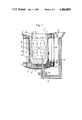
- FIG. 1 diagrammatically illustrates an induction crucible furnace in accordance with the invention with the melt fed in at the bottom of the crucible and the melt discharged from the crucible through a pouring spot.
- the crucible is cylindrical, open at its top and closed at its bottom except for an opening for feeding melt into the crucible.
- a vertical connecting tube with a funnel at its top connects with the opening in the bottom of the crucible to feed the melt.
- External heating of the coil is by means of coil surrounding the cylindrical surface of the crucible.
- a pouring spout is provided for discharging the melt from the crucible upon tilting the crucible.
- FIG. 2 is a modification of FIG. 1 showing an induction crucible furnace with an inlet and an outlet in the bottom.
- FIG. 3 is a vacuum-tight embodiment of FIG. 2 with a vacuum pump for drawing off the atmosphere above the bath level.
- FIG. 4 is a variant of FIG. 3, in which the inlet and the outlet form a structural unit and can be used as a sliding shut-off valve.
- the input of the melt to the crucible furnace is arranged below the bath level in the furnace.
- One means of accomplishing this is to provide an inlet for the melt input to the crucible furnace in the bottom of the crucible.
- the pouring of the melt from the crucible can then be through the spout.
- Outlet means for the discharge of melt from the crucible can also be provided in the bottom of the crucible.
- Such an induction crucible furnace with inlet and outlet in the bottom is particularly suitable if the treatment vessel is to be evacuated in addition.
- FIGS. 1-4 Schematic embodiment examples of the invention are shown in FIGS. 1-4.
- FIG. 1 shows an induction crucible furnace 1 with a cylindrical crucible 2 which is provided with an inlet 3 for the melt and a pouring spout 4 for discharge of melt.
- the crucible 2 is filled with melt 5 up to the bath level or liquid level 6.
- the crucible 2 is mounted on a refractory bottom 7 which is supported on a metallic bottom plate 8.
- the metallic bottom plate 8 together with a lower reinforcement ring 9, vertical struts 20 and an upper reinforcement ring 11, forms the furnace frame.
- the reinforcement ring 11 is in the region of the pouring spout 4 to enable the pouring spout 4 to rest on it.
- the crucible 2 is surrounded by a coil insert 12 and 13.
- Magnet yokes 18 represent the magnetic return for the lines of force produced in the active coil.
- clamping devices which consist of a lever 19, a screw spindle 20 and a compression spring 21.
- the coils 12 and 13, by means of the clamping device, are pushed against the reinforcement ring 11.
- the bath motion or local circulation of the melt 5 in the crucible 2 generated by the induction is indicated by the lines 22.
- the inlet opening 3 in the crucible bottom 27 is connected to the connecting tube 23, which leads to the funnel 24, via flanges 25 or the like.
- a pipeline with a refractory lining has been used.
- This pipeline is further provided with heat insulation 26 in order to prevent heat radiation to the outside and excessive cooling of the melt contained in the pipeline.
- the static bath pressure in the furnace which corresponds to the bath level 6 and that in the inlet line 23 or the funnel 24 must be equal. It is therefore possible to influence the bath level in the furnace 6 via the bath level in the line 23 or funnel 24.
- FIG. 2 shows another embodiment of FIG. 1.
- the discharge opening 30 for the melt like the inlet opening 3, is arranged in the bottom 27 of the crucible 2, whereas there is no discharge opening in the bottom 27 of the crucible 2 of FIG. 1.
- a connecting line 31 is connected to the discharge opening 30 via flanges 32 and line 31 then rises to the pouring spout 33.
- Line 23 and line 31 have refractory linings and heat losses are minimized by covering lines 23 and 31 with thermal insulation 26 and 34, respectively.
- the inlet opening 3 and the outlet opening 30 are located close together, there is no difficulty because a direct passage of the melt from the inlet to the outlet is prevented by the strong stirring action of the induction current.
- the local circulation or bath motion of the melt is indicated by lines 22.
- the device can be drained at the end of the treatment by tilting or, if the induction crucible furnace cannot be tilted, via a bottom plug, not shown.
- FIG. 3 shows a further embodiment of the invention, in which the crucible 2 is provided with a lid 40 which closes the crucible 2 tight for operation under a vacuum.
- the atmosphere above the bath level 6 can be drawn-off through the opening 41 by means of a vacuum pump.
- the vacuum pump 43 is connected on its suction side to the opening 41 via the connecting line 42 and the flanges 45.
- the gases removed from the atmosphere above liquid level 6 in crucible 2 through opening 41 and connecting line 42 are discharged by vacuum pump 43 through line 44.
- heating of melt 5 in crucible 2 can be combined with a simultaneous application of vacuum.
- the latter is particularly practical since, due to the already mentioned strong bath motions in the induction crucible furnace, practically all parts of the melt are washed to the bath surface and are therefore subjected directly to the action of the vacuum.
- this arrangement has the further advantage that the inlet and outlet points 24 and 33 can be lower than in the embodiment according to FIG. 2. This has the advantage that after a treatment, i.e., after the vacuum is removed, less residual melt remains in the treatment unit. In addition, the connecting lines 46 and 47 are naturally shorter.
- FIG. 4 shows an embodiment with the inlet and outlet lines 48 and 49 as one structural unit 50.
- This embodiment has the further advantage that the unit 50 can be turned about its vertical axis which coincides with the vertical axis 51 of the crucible furnace, such that the inlet opening 3 and the outlet opening 40 are shut off.
- This unit acts as a sliding valve.
- the inlet can also be designed differently.
- the invention provides an induction crucible furnace as continuous flow heater for molten metals for maintaining or increasing the temperature level of the metal melt and for increasing the service life of the crucible such that it corresponds approximately to the service life of the crucible in a normal induction crucible furnace, by arranging the inlet of the melt to the crucible furnace below the bath level in the furnace, for instance, in the bottom of the crucible.
- the pouring can be accomplished via the spout or also via an outlet provided in the bottom of the crucible.
Landscapes
- Physics & Mathematics (AREA)
- Electromagnetism (AREA)
- Crucibles And Fluidized-Bed Furnaces (AREA)
Applications Claiming Priority (2)
| Application Number | Priority Date | Filing Date | Title |
|---|---|---|---|
| DE19823229367 DE3229367A1 (de) | 1982-08-06 | 1982-08-06 | Durchlauferhitzer fuer schmelzfluessige metalle |
| DE3229367 | 1982-08-06 |
Publications (1)
| Publication Number | Publication Date |
|---|---|
| US4486889A true US4486889A (en) | 1984-12-04 |
Family
ID=6170276
Family Applications (1)
| Application Number | Title | Priority Date | Filing Date |
|---|---|---|---|
| US06/519,096 Expired - Fee Related US4486889A (en) | 1982-08-06 | 1983-08-01 | Continuous-flow heater for molten metals |
Country Status (4)
| Country | Link |
|---|---|
| US (1) | US4486889A (de) |
| EP (1) | EP0102479A3 (de) |
| JP (1) | JPS5944574A (de) |
| DE (1) | DE3229367A1 (de) |
Cited By (6)
| Publication number | Priority date | Publication date | Assignee | Title |
|---|---|---|---|---|
| US5267258A (en) * | 1991-09-20 | 1993-11-30 | Fuji Electric Co., Ltd. | Fast melting induction furnace with pressing cover |
| US6393044B1 (en) * | 1999-11-12 | 2002-05-21 | Inductotherm Corp. | High efficiency induction melting system |
| US20050098294A1 (en) * | 2003-11-12 | 2005-05-12 | Howard Robert W. | Casting device and method |
| US20070157761A1 (en) * | 2006-01-11 | 2007-07-12 | Bratina James E | Use of an induction furnace for the production of iron from ore |
| US20080130704A1 (en) * | 2006-11-30 | 2008-06-05 | Lapoint Albert E | Electroslag smelting system and method |
| JP2022546458A (ja) * | 2019-08-30 | 2022-11-04 | ダイソン・テクノロジー・リミテッド | マルチゾーンるつぼ装置 |
Citations (4)
| Publication number | Priority date | Publication date | Assignee | Title |
|---|---|---|---|---|
| US3056847A (en) * | 1958-04-12 | 1962-10-02 | Junker Otto | Vacuum melting induction furnace |
| US3230073A (en) * | 1962-07-20 | 1966-01-18 | Asea Ab | Process for vacuum degassing with electromagnetic stirring |
| US3472942A (en) * | 1964-05-25 | 1969-10-14 | Campbell James S | Molten metal charging means for a furnace |
| US3819842A (en) * | 1972-04-24 | 1974-06-25 | Elin Union Ag | Method and furnace for maintaining the temperature level of metal melts |
Family Cites Families (2)
| Publication number | Priority date | Publication date | Assignee | Title |
|---|---|---|---|---|
| US3320348A (en) * | 1964-08-07 | 1967-05-16 | V & V Companies Inc | Induction melting furnace |
| US3700779A (en) * | 1970-07-30 | 1972-10-24 | Est Aciers Fins | Method of treatment of liquid steel under vacuum |
-
1982
- 1982-08-06 DE DE19823229367 patent/DE3229367A1/de not_active Withdrawn
-
1983
- 1983-07-08 EP EP83106697A patent/EP0102479A3/de not_active Withdrawn
- 1983-08-01 US US06/519,096 patent/US4486889A/en not_active Expired - Fee Related
- 1983-08-05 JP JP58142630A patent/JPS5944574A/ja active Pending
Patent Citations (4)
| Publication number | Priority date | Publication date | Assignee | Title |
|---|---|---|---|---|
| US3056847A (en) * | 1958-04-12 | 1962-10-02 | Junker Otto | Vacuum melting induction furnace |
| US3230073A (en) * | 1962-07-20 | 1966-01-18 | Asea Ab | Process for vacuum degassing with electromagnetic stirring |
| US3472942A (en) * | 1964-05-25 | 1969-10-14 | Campbell James S | Molten metal charging means for a furnace |
| US3819842A (en) * | 1972-04-24 | 1974-06-25 | Elin Union Ag | Method and furnace for maintaining the temperature level of metal melts |
Cited By (7)
| Publication number | Priority date | Publication date | Assignee | Title |
|---|---|---|---|---|
| US5267258A (en) * | 1991-09-20 | 1993-11-30 | Fuji Electric Co., Ltd. | Fast melting induction furnace with pressing cover |
| US6393044B1 (en) * | 1999-11-12 | 2002-05-21 | Inductotherm Corp. | High efficiency induction melting system |
| US20050098294A1 (en) * | 2003-11-12 | 2005-05-12 | Howard Robert W. | Casting device and method |
| US20070157761A1 (en) * | 2006-01-11 | 2007-07-12 | Bratina James E | Use of an induction furnace for the production of iron from ore |
| US7413590B2 (en) * | 2006-01-11 | 2008-08-19 | Heritage Environmental Services, Llc | Use of an induction furnace for the production of iron from ore |
| US20080130704A1 (en) * | 2006-11-30 | 2008-06-05 | Lapoint Albert E | Electroslag smelting system and method |
| JP2022546458A (ja) * | 2019-08-30 | 2022-11-04 | ダイソン・テクノロジー・リミテッド | マルチゾーンるつぼ装置 |
Also Published As
| Publication number | Publication date |
|---|---|
| JPS5944574A (ja) | 1984-03-13 |
| EP0102479A2 (de) | 1984-03-14 |
| EP0102479A3 (en) | 1984-09-05 |
| DE3229367A1 (de) | 1984-02-09 |
Similar Documents
| Publication | Publication Date | Title |
|---|---|---|
| US3367396A (en) | Installation for the vacuum treatment of melts, in particular steel melts, and process for its operation | |
| US4486889A (en) | Continuous-flow heater for molten metals | |
| US3136834A (en) | Apparatus for continuously degassing molten metals by evacuation | |
| JPH03216264A (ja) | 金属汚染防止方法 | |
| US6101212A (en) | Sealed evacuatable crucible for inductive melting or superheating | |
| US3235243A (en) | Apparatus for producing ultraclean alloy steels | |
| US3273212A (en) | Method of operating an electric furnace | |
| US3610600A (en) | Continuously operable plant for degassing and pouring metal melts | |
| US2821378A (en) | Tapping device for molten metals | |
| US5590151A (en) | Process for melting scrap iron in an electric furnace and installation for implementing the process | |
| US4779287A (en) | Tiltable metallurgical furnace vessel | |
| GB2270145A (en) | Induction melting and casting furnace | |
| US3737302A (en) | Method of treatment of liquid steel under vacuum | |
| US3811001A (en) | Tiltable induction furnace for molten metals | |
| US2773750A (en) | Furnace | |
| US2826624A (en) | Vapor shield for induction furnace | |
| KR930004477B1 (ko) | 금속을 유도 용융하는 장치 및 방법 | |
| US3199853A (en) | Bell-type annealing furnace and method of sealing same | |
| US3700779A (en) | Method of treatment of liquid steel under vacuum | |
| US5215709A (en) | Method and device for treatment of metal baths by means of a material having a high gas vapor potential | |
| EP0795037B1 (de) | vorrichtung zur behandlung von schmelzen mit reaktiven materialien die niedrigen oder hohen gasanteil erzeugen | |
| US5153896A (en) | Metallurgical vessel equipped with at least one electrode passing through its wall | |
| US3107268A (en) | Melting furnace | |
| US3934863A (en) | Apparatus for refining molten metal and molten metal refining process | |
| US4363653A (en) | Method and apparatus for melting solid pieces of metal |
Legal Events
| Date | Code | Title | Description |
|---|---|---|---|
| AS | Assignment |
Owner name: BROWN, BOVERI & CIE AG, D-6800 MANNHEIM, GERMANY A Free format text: ASSIGNMENT OF ASSIGNORS INTEREST.;ASSIGNORS:HEGEWALDT, FRITZ;DOTSCH, ERWIN;REEL/FRAME:004279/0504 Effective date: 19830711 |
|
| REMI | Maintenance fee reminder mailed | ||
| REIN | Reinstatement after maintenance fee payment confirmed | ||
| FP | Lapsed due to failure to pay maintenance fee |
Effective date: 19881204 |
|
| REMI | Maintenance fee reminder mailed | ||
| LAPS | Lapse for failure to pay maintenance fees | ||
| FP | Lapsed due to failure to pay maintenance fee |
Effective date: 19921208 |
|
| STCH | Information on status: patent discontinuation |
Free format text: PATENT EXPIRED DUE TO NONPAYMENT OF MAINTENANCE FEES UNDER 37 CFR 1.362 |