US4486159A - Rotor for a rotary engine - Google Patents
Rotor for a rotary engine Download PDFInfo
- Publication number
- US4486159A US4486159A US06/608,923 US60892384A US4486159A US 4486159 A US4486159 A US 4486159A US 60892384 A US60892384 A US 60892384A US 4486159 A US4486159 A US 4486159A
- Authority
- US
- United States
- Prior art keywords
- rotor
- insert
- cavity
- portions
- axial
- Prior art date
- Legal status (The legal status is an assumption and is not a legal conclusion. Google has not performed a legal analysis and makes no representation as to the accuracy of the status listed.)
- Expired - Lifetime
Links
Images


Classifications
-
- F—MECHANICAL ENGINEERING; LIGHTING; HEATING; WEAPONS; BLASTING
- F02—COMBUSTION ENGINES; HOT-GAS OR COMBUSTION-PRODUCT ENGINE PLANTS
- F02B—INTERNAL-COMBUSTION PISTON ENGINES; COMBUSTION ENGINES IN GENERAL
- F02B53/00—Internal-combustion aspects of rotary-piston or oscillating-piston engines
- F02B53/10—Fuel supply; Introducing fuel to combustion space
-
- F—MECHANICAL ENGINEERING; LIGHTING; HEATING; WEAPONS; BLASTING
- F02—COMBUSTION ENGINES; HOT-GAS OR COMBUSTION-PRODUCT ENGINE PLANTS
- F02B—INTERNAL-COMBUSTION PISTON ENGINES; COMBUSTION ENGINES IN GENERAL
- F02B55/00—Internal-combustion aspects of rotary pistons; Outer members for co-operation with rotary pistons
- F02B55/02—Pistons
- F02B55/04—Cooling thereof
- F02B55/06—Cooling thereof by air or other gas
-
- F—MECHANICAL ENGINEERING; LIGHTING; HEATING; WEAPONS; BLASTING
- F02—COMBUSTION ENGINES; HOT-GAS OR COMBUSTION-PRODUCT ENGINE PLANTS
- F02B—INTERNAL-COMBUSTION PISTON ENGINES; COMBUSTION ENGINES IN GENERAL
- F02B53/00—Internal-combustion aspects of rotary-piston or oscillating-piston engines
- F02B2053/005—Wankel engines
-
- F—MECHANICAL ENGINEERING; LIGHTING; HEATING; WEAPONS; BLASTING
- F05—INDEXING SCHEMES RELATING TO ENGINES OR PUMPS IN VARIOUS SUBCLASSES OF CLASSES F01-F04
- F05C—INDEXING SCHEME RELATING TO MATERIALS, MATERIAL PROPERTIES OR MATERIAL CHARACTERISTICS FOR MACHINES, ENGINES OR PUMPS OTHER THAN NON-POSITIVE-DISPLACEMENT MACHINES OR ENGINES
- F05C2201/00—Metals
- F05C2201/04—Heavy metals
- F05C2201/0433—Iron group; Ferrous alloys, e.g. steel
- F05C2201/0436—Iron
- F05C2201/0439—Cast iron
- F05C2201/0442—Spheroidal graphite cast iron, e.g. nodular iron, ductile iron
-
- Y—GENERAL TAGGING OF NEW TECHNOLOGICAL DEVELOPMENTS; GENERAL TAGGING OF CROSS-SECTIONAL TECHNOLOGIES SPANNING OVER SEVERAL SECTIONS OF THE IPC; TECHNICAL SUBJECTS COVERED BY FORMER USPC CROSS-REFERENCE ART COLLECTIONS [XRACs] AND DIGESTS
- Y02—TECHNOLOGIES OR APPLICATIONS FOR MITIGATION OR ADAPTATION AGAINST CLIMATE CHANGE
- Y02T—CLIMATE CHANGE MITIGATION TECHNOLOGIES RELATED TO TRANSPORTATION
- Y02T10/00—Road transport of goods or passengers
- Y02T10/10—Internal combustion engine [ICE] based vehicles
- Y02T10/12—Improving ICE efficiencies
Definitions
- This invention relates to a rotor for a rotary internal combustion engine of the kind, hereinafter referred to as being of the kind specified, in which a rotary piston or rotor, rotates within a cavity in a housing, the rotor and the wells of the cavity being so shaped that working chambers are formed therebetween which vary in volume as the rotor rotates and the cavity being provided with inlet and exhaust ports.
- the invention relates to a rotor for a so-called Wankel engine in which the housing has a two-lobed epitrochoidal bore which forms the cavity and has end plates which form axially spaced end walls closing the cavity, and the rotor has an outer profile of generally equilateral triangular shape with outwardly curved sides such as convexly curved sides, and is mounted on an eccentric journal of a main shaft and is geared to rotate in a planetary manner within the cavity at one third of the speed of rotation of the main shaft.
- One method of cooling the rotor of such an engine is to form one or more passageways in the rotor which form an induction passage to the working chambers so that induced air, or a proportion of induced air, is drawn through and thereby cools the rotor.
- cooling air may be forced through the passageways by an external fan or pump.
- An example of such an engine is shown in Canadian Pat. No. 695,953.
- Such engines are hereinafter referred to as having an air-cooled rotor.
- fuel may be introduced into the induced air to pass through the rotor therewith and such an engine, although specifically referred to as having an air-cool rotor, is more specifically referred to hereinafter as having a charge-cooled rotor.
- objects of the invention are to provide a new and improved rotor for a rotary engine of the type specified and a new and improved engine, wherein the above mentioned problem is overcome or is reduced.
- an air-cooled rotor in a rotary engine of the kind specified comprising a body having, in a plane transverse to the axis of rotation of the rotor, an outer profile of generally equilateral triangular shape with outwardly curved sides and an inner profile providing part peripheral location portions in the regions of the mid-points of the rotor sides in engagement with an insert, the insert providing a bearing part and an indexing gear of the rotor, the inner profile of the body adjacent each apex of the rotor, being radially outwards of the insert over the entire axial length of the body, thereby providing gaps between the location portions so that axial cooling passages are formed, peripherally bounded by the rotor body and the insert which extend continuously over the entire axial length of the body, and the engine having means to pass cooling air axially through said axial cooling passages from one end of the body to the other end thereof.
- the present invention overcomes the problem of rotor failure described above in the following way.
- air and charge-cooled rotors in engines of the kind specified have been cast in one piece and possess an outer profile of generally equilateral triangular configuration with curved sides in the same way as the rotor of the present invention, but the inner profile has been of generally cylindrical configuration and provided with a rolling element bearing outer race and indexing gear.
- the bearing outer race has been provided by means of an insert received within the cylindrical inner profile and the indexing gear has been machined directly in the inner profile of the rotor or, alternatively, machined in an axial extension of the insert so that the insert has provided both the bearing and the indexing gear.
- rotor cooling has been effected by forming axial cooling passages adjacent each apex of the rotor. These axial passages were bounded on their radially inner side, for at least part of their axial length through the rotor, by bridging portions cast integrally with the remainder of the rotor, these bridging portions generally also providing part of the cylindrical surface with which the insert is engaged. It has been found that the bridging portions fracture when the rotor is subjected to the above mentioned high mechanical and thermal stresses, resulting in failure of the engine.
- the casting material which is normally SG iron
- the ductility is reduced.
- difficulties arise with machining the rotor casting if the hardness of the metal is too high. If hardening is carried out after machining then unacceptable distortion may occur during hardening.
- bridging portions are cast relatively thin to give more flexibility and resistance to thermal stresses they are weaker mechanically. If they are thicker, and therefore stronger mechanically, they are more prone to thermal stresses.
- the rotor casting can now conveniently be cast without having to use separate cores and therefore the cost of production is reduced. Also because the bridging portions have been eliminated, the area available for axial cooling passages can be made larger than has conventionally been possible.
- the location portions do not project peripherally beyond the peripherally widest dimension of the axial cooling passages since any projection beyond the widest peripheral dimension reduces the cross-sectional area of the passage compared with that which it would have if the location portions terminated at the widest peripheral dimension.
- the location portions can project beyond the maximum peripheral dimension of the axial cooling passages but provide gaps of relatively small width in the peripheral direction between the portions.
- the minimum width in these circumstances is determined solely by ease of manufacture. For example, it is preferred to produce the rotor with the gaps by casting in which case a six millimeter gap would be about the minimum practical width. If desired however, the gaps could be produced by machining in which case they could be considerably smaller.
- the minimum width is that necessary to permit of relative movement between adjacent location portions thereby to avoid thermal and other stresses discussed above.
- the insert is of a one-piece turned steel construction to maintain manufacturing costs low, and to ensure that the insert has sufficient radial rigidity to withstand the stresses imposed thereon, although if required, the insert may be of composite sectional construction.
- the body between the inner and outer profiles may be of such configuration to provide the rotor with the necessary strength without consideration of the strength of the insert, to withstand gas pressures and inertia loads imposed thereon in use, although if required, the rotor body and, the insert may be suitably designed together to possess the necessary resistance to deformation, despite the insert being located with less than the whole of its periphery in engagement with the rotor body.
- the part-peripheral location portions may be part circular and the insert may be circular in cross-section, although other configurations are possible.
- the insert may be an interference fit with the part-peripheral location portions of the rotor body and additional suitable securing means may be provided to prevent movement, such as rotation and/or axial movement of the insert, relative to the rotor body.
- Said securing means may comprise at least one member received in an axial bore, part of the circumference of which is formed in said insert and part of the circumference of which is formed in said rotor body.
- Said member may comprise, a roll pin received in a non-threaded axial bore, to prevent relative rotational movement, although preferably said member may be threaded and be received in a threaded axial bore, to prevent relative axial movement also.
- Three such members may be provided.
- the wall of the or each axial cooling passageway in the rotor body may be provided with cooling fins.
- the cooling fins are disposed axially.
- the engine may be of the so-called Wankel type.
- FIG. 1 is an end elevation of a rotor in accordance with the first aspect of the invention
- FIG. 2 is a section on the line 2--2 of FIG. 1;
- FIG. 3 is a longitudinal cross-sectional view through an insert for the rotor of FIGS. 1 and 2;
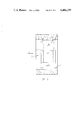
- FIG. 4 is a diagrammatic cross-section through an engine according to the second aspect of the invention.
- FIG. 5 is a section on the line 5--5 of FIG. 4;
- FIG. 6 is an end elevation of a prior art rotor
- FIG. 7 is an end elevation of a rotor in accordance with a modification of the first aspect of the invention.
- a rotary engine which is of the so-called Wankel type and comprises a stationary housing 10 which has a two-lobed epitrochoidal bore 11 therethrough and end plates 12a, 12b to close the bore at the ends thereof.
- a rotor 13 of equilateral triangular shape having outwardly curved sides is rotatably mounted by a needle bearing 14 upon an eccentric journal 15 of a main shaft 16 which is rotatably mounted in bearings 17 mounted in the end plates 12a, 12b and has a fly wheel 18 and a balance weight 19 secured to its opposite extremities.
- Sealing strips 20 carried at the apices of the rotor 13 maintain sealing contact with the peripheral wall 21 of the epitrochoidal bore 11 as the rotor 13 rotates in planetary manner within the bore 11.
- the rotor 13 has an internally toothed indexing gear 22 which meshes with an externally toothed fixed gear 23 carried by the end plate 12a, and the gear 22 controls the planetary motion of the rotor 13, the teeth ratios being such that the rotor 13 rotates once for every three revolutions of the main shaft 16.
- the induction system of the engine is such that air flows through and cools the rotor 13 and air passes in sequence through an inlet 24, a passage 25 and an opening 26 in end plate 12b, passageways 27 in apex portions of the rotor 13 and through an opening 28 in the end plate 12a.
- the induced air also flows through an aperture 29 in the eccentric journal 15 which is thereby cooled.
- Fuel may be introduced into the inducted air flow by means of a carburettor either before the air passes into the inlet 24, such that it is an air/fuel mixture which flows through the rotor 13, so that the rotor 13 is charge-cooled, or as the air flows through the pipe 33 from the chamber 32, or alternatively it may be metered directly into a working chamber by fuel injection means. In both of the latter cases the rotor is air-cooled.
- the rotor 13 comprises a body having an outer profile of generally equilateral triangular shape with three outwardly curved sides 35 which meet at apices 36 whereat the above mentioned sealing strips 20 are provided.
- the rotor body also has an inner profile which provides part-circular location portions 37, which are of different diameters at different positions axially of the rotor as shown in FIG. 2 where the stepped nature of the location portions 37 is best illustrated.
- the external surface 40 of the insert 39 is adapted to be an interference fit at local axial bands 41 with parts 42 of the location portions 37.
- the gaps between the adjacent location portions 37 are, in the present example, of a circumferential width equal to the maximum circumferential width of each passageway 27.
- the location portions 37 may project partly across the "mouth" of the recess so as to lie inside the maximum circumferential width of the recess, as illustrated at 37a in FIG. 7.
- the minimum width of the gap is determined mainly by practical considerations as to the way in which it is desired to manufacture the rotor body.
- the minimum practical gap is of approximately 6 mm width. If however the gap is to be machined in a previously continuous location portion 37, the gap can be of a width down to one or two thousandths of an inch, so long as there is sufficient gap to permit movement between adjacent location portions 37 to avoid the above described thermal and mechanical stresses.
- the internal surface of the insert 39 provides, in the region indicated at 43, the outer race of the needle bearing 14 and in the region indicated at 44, is machined to provide the indexing gear 22.
- a plurality of cylindrical bores 45, 45a are formed in the assembly of insert 39 and rotor body so that approximately half the circumference of each bore 45 lies within the insert 39 and the other half 45a within the rotor 13, and a roll pin (not shown) is driven into the bores 45 and 45a.
- at least one threaded bore is similarly formed between the insert and rotor body as indicated at 46, 46a, and a grub screw is received within each bore 46, 46a to further secure the connection and also to prevent axial movement of the insert 39 relative to the rotor 13.
- the rotor body is made as a one-piece casting and there is no opening in the rotor body between the external surface thereof and the internal surface thereof, which comprises the location portions 37 and the surface parts 37b of the recesses.
- the above mentioned passageways 27 are formed between the insert 39 and the parts 37b of the internal surface of the rotor body.
- rotor body is indicated at 100 and comprises a generally equilateral triangular shaped external surface 101, having outwardly curved sides 102 which meet at apices 103, at which sealing strips (not shown) are provided.
- the internal surface of the rotor 104 (which corresponds to the location portions 37 and surface parts 37b of the rotor body embodying the present invention) is provided on an inner portion which extends continuously circumferentially of the rotor for at least some axial proportion of the rotor, and hence provides bridging portions 105 of the inner part which bridge voids 106 formed in the rotor body so that the voids 106 provide passageways 107 corresponding to the passageways 27 of the rotor embodying the present invention.
- the bridging portions 105 are integral with remainder of the rotor body.
- An insert is received within the surface 104 to provide an outer race for a needle bearing and may, if desired, also be machined to provide gear teeth for the internal indexing gear of the rotor.
- the indexing gear is machined directly in the material of the inner portion of the rotor.
- the present invention differs in the absence of the bridging portions 105, in other words there is a circumferentially extending discontinuity or gap in the part of the rotor which provides the internal surface portions with which the insert is engaged, over the full axial length of the rotor, and the rotor body but particularly adjacent the apices 36 and in the regions around the positions indicated at R, is made adequately strong to provide the desired strength to withstand the bending moments imposed on the rotor sides, in use, in the absence of any bridging portions. It has been found that as a result, the rotor does not fail.
- each passage 27 is provided with five cooling ribs or fins 47 to facilitate heat transfer between the cooling air or air/fuel mixture and the rotor.
- the fins may be omitted if desired or be of a different profile to that illustrated.
- the rotor 13 is made as a casting in spheroidal graphite (SG) iron, whilst the insert 39 is made as a forging in an appropriate bearing steel or from a hollow bar of bearing steel. It will, of course, be appreciated that other suitable materials may be used if desired.
- SG spheroidal graphite
- the insert 39 comprises a one piece construction, but if desired, the insert 13 may be sectional. Where the insert 13 is sectional, two or more sections of the insert 13 may engage any location portion 37.
- the rotor body of the rotor 13 may be designed to withstand the thermal and mechanical stresses imposed thereon, without any consideration as to the strength of the insert 13. However if required, the rotor body and insert together, may be designed to withstand the stresses.
- the insert 39 will need to be adequately strong to withstand the forces imposed thereon during operation of the engine.
Landscapes
- Engineering & Computer Science (AREA)
- Chemical & Material Sciences (AREA)
- Combustion & Propulsion (AREA)
- Mechanical Engineering (AREA)
- General Engineering & Computer Science (AREA)
- Rotary Pumps (AREA)
- Iron Core Of Rotating Electric Machines (AREA)
- Lubrication Of Internal Combustion Engines (AREA)
- Supercharger (AREA)
Abstract
Description
Claims (10)
Applications Claiming Priority (2)
| Application Number | Priority Date | Filing Date | Title |
|---|---|---|---|
| GB8119075 | 1981-06-20 | ||
| GB8119075 | 1981-06-20 |
Related Parent Applications (1)
| Application Number | Title | Priority Date | Filing Date |
|---|---|---|---|
| US06378436 Continuation | 1982-05-17 |
Publications (1)
| Publication Number | Publication Date |
|---|---|
| US4486159A true US4486159A (en) | 1984-12-04 |
Family
ID=10522691
Family Applications (1)
| Application Number | Title | Priority Date | Filing Date |
|---|---|---|---|
| US06/608,923 Expired - Lifetime US4486159A (en) | 1981-06-20 | 1984-05-11 | Rotor for a rotary engine |
Country Status (5)
| Country | Link |
|---|---|
| US (1) | US4486159A (en) |
| EP (1) | EP0068104B1 (en) |
| JP (1) | JPS58140426A (en) |
| DE (1) | DE3261921D1 (en) |
| GB (1) | GB2100795B (en) |
Cited By (11)
| Publication number | Priority date | Publication date | Assignee | Title |
|---|---|---|---|---|
| US4772189A (en) * | 1985-11-20 | 1988-09-20 | Norton Motors Limited | Rotor for a rotary engine |
| US4898522A (en) * | 1988-04-07 | 1990-02-06 | Teledyne Industries, Inc. | System for cooling the rotary engine rotor |
| US5017087A (en) * | 1984-07-13 | 1991-05-21 | Sneddon John L | Multi-functional rotary hydraulic machine systems |
| US6146120A (en) * | 1998-07-29 | 2000-11-14 | Jenn Feng Industrial Co., Ltd. | Rotary engine having an improved rotor structure |
| US20100300402A1 (en) * | 2009-05-19 | 2010-12-02 | Dankwart Eiermann | Rotary piston for a rotary piston engine and rotary piston engine |
| US20100313844A1 (en) * | 2008-02-13 | 2010-12-16 | Garside David W | Rotary Piston Internal Combustion Engine |
| EP2497902A1 (en) * | 2011-03-10 | 2012-09-12 | Uav Engines Ltd | Rotary Engine Rotor |
| WO2016145247A1 (en) * | 2015-03-10 | 2016-09-15 | Liquidpiston, Inc. | High power density and efficiency epitrochoidal rotary engine |
| US9644570B2 (en) | 2006-08-02 | 2017-05-09 | Liquidpiston, Inc. | Hybrid cycle rotary engine |
| US10196970B2 (en) | 2008-08-04 | 2019-02-05 | Liquidpiston, Inc. | Isochoric heat addition engines and methods |
| US20220243645A1 (en) * | 2018-12-12 | 2022-08-04 | Poul Henrik Woelfle | Rotary piston engine having optimized internal cooling of intake air |
Families Citing this family (5)
| Publication number | Priority date | Publication date | Assignee | Title |
|---|---|---|---|---|
| GB8630503D0 (en) * | 1986-12-20 | 1987-01-28 | Norton Motors Ltd | Rotary engine |
| US6125813A (en) * | 1997-06-09 | 2000-10-03 | Patrick Power Products, Inc. | Prechamber combustion for a rotary diesel engine |
| DE102011014861B4 (en) * | 2011-03-24 | 2015-11-05 | Paul Andreas Woelfle | Rotary piston engine and cooling method for a rotary piston engine |
| CN102817707A (en) * | 2012-09-11 | 2012-12-12 | 优华劳斯汽车系统(上海)有限公司 | Rotary piston engine |
| GB2524527A (en) * | 2014-03-25 | 2015-09-30 | Gilo Ind Res Ltd | Cooled rotary engine rotor |
Citations (5)
| Publication number | Priority date | Publication date | Assignee | Title |
|---|---|---|---|---|
| US3042009A (en) * | 1958-10-02 | 1962-07-03 | Nsu Motorenwerke Ag | Cooling arrangement for rotary mechanisms |
| US3098605A (en) * | 1960-05-27 | 1963-07-23 | Curtiss Wright Corp | Cooling and lubrication system for rotary mechanisms |
| CA695953A (en) * | 1964-10-13 | Bentele Max | Air cooling system for rotary mechanisms | |
| US3802810A (en) * | 1971-02-10 | 1974-04-09 | Schmidt K Gmbh | Light alloy piston for rotary engines |
| DE2315595A1 (en) * | 1973-03-29 | 1974-10-17 | Schmidt Gmbh Karl | LIGHT ALLOY PISTON FOR CIRCULAR PISTON COMBUSTION ENGINES |
Family Cites Families (5)
| Publication number | Priority date | Publication date | Assignee | Title |
|---|---|---|---|---|
| IT649971A (en) * | 1960-06-01 | |||
| DE1283594B (en) * | 1965-11-27 | 1970-06-11 | ||
| DE1551095C3 (en) * | 1966-09-07 | 1974-06-06 | Daimler-Benz Ag, 7000 Stuttgart | Polygonal piston of a rotary piston internal combustion engine |
| DE1961134B1 (en) * | 1969-12-05 | 1971-04-08 | Kloeckner Humboldt Deutz Ag | Multi-part piston for internal-axis rotary piston machine |
| GB1386811A (en) * | 1972-04-29 | 1975-03-12 | Birmingham Small Arms Co Ltd | Rotary piston internal combustion engines |
-
1982
- 1982-05-03 DE DE8282103775T patent/DE3261921D1/en not_active Expired
- 1982-05-03 EP EP82103775A patent/EP0068104B1/en not_active Expired
- 1982-05-25 GB GB08215207A patent/GB2100795B/en not_active Expired
- 1982-06-19 JP JP57104712A patent/JPS58140426A/en active Pending
-
1984
- 1984-05-11 US US06/608,923 patent/US4486159A/en not_active Expired - Lifetime
Patent Citations (5)
| Publication number | Priority date | Publication date | Assignee | Title |
|---|---|---|---|---|
| CA695953A (en) * | 1964-10-13 | Bentele Max | Air cooling system for rotary mechanisms | |
| US3042009A (en) * | 1958-10-02 | 1962-07-03 | Nsu Motorenwerke Ag | Cooling arrangement for rotary mechanisms |
| US3098605A (en) * | 1960-05-27 | 1963-07-23 | Curtiss Wright Corp | Cooling and lubrication system for rotary mechanisms |
| US3802810A (en) * | 1971-02-10 | 1974-04-09 | Schmidt K Gmbh | Light alloy piston for rotary engines |
| DE2315595A1 (en) * | 1973-03-29 | 1974-10-17 | Schmidt Gmbh Karl | LIGHT ALLOY PISTON FOR CIRCULAR PISTON COMBUSTION ENGINES |
Cited By (22)
| Publication number | Priority date | Publication date | Assignee | Title |
|---|---|---|---|---|
| US5017087A (en) * | 1984-07-13 | 1991-05-21 | Sneddon John L | Multi-functional rotary hydraulic machine systems |
| US4772189A (en) * | 1985-11-20 | 1988-09-20 | Norton Motors Limited | Rotor for a rotary engine |
| US4898522A (en) * | 1988-04-07 | 1990-02-06 | Teledyne Industries, Inc. | System for cooling the rotary engine rotor |
| US6146120A (en) * | 1998-07-29 | 2000-11-14 | Jenn Feng Industrial Co., Ltd. | Rotary engine having an improved rotor structure |
| US9644570B2 (en) | 2006-08-02 | 2017-05-09 | Liquidpiston, Inc. | Hybrid cycle rotary engine |
| US20100313844A1 (en) * | 2008-02-13 | 2010-12-16 | Garside David W | Rotary Piston Internal Combustion Engine |
| US8424504B2 (en) * | 2008-02-13 | 2013-04-23 | David W. Garside | Rotary piston internal combustion engine |
| US10196970B2 (en) | 2008-08-04 | 2019-02-05 | Liquidpiston, Inc. | Isochoric heat addition engines and methods |
| US20100300402A1 (en) * | 2009-05-19 | 2010-12-02 | Dankwart Eiermann | Rotary piston for a rotary piston engine and rotary piston engine |
| US8528518B2 (en) * | 2009-05-19 | 2013-09-10 | Wankel Supertec Gmbh | Rotary piston for a rotary piston engine and rotary piston engine |
| CN103518036A (en) * | 2011-03-10 | 2014-01-15 | Uav发动机有限公司 | Rotary engine rotor |
| US20140069273A1 (en) * | 2011-03-10 | 2014-03-13 | Uav Engines Ltd. | Rotary Engine Rotor |
| CN103518036B (en) * | 2011-03-10 | 2016-11-09 | Uav发动机有限公司 | Rotary engine rotor |
| US9518658B2 (en) * | 2011-03-10 | 2016-12-13 | Uav Engines Ltd. | Rotary engine rotor |
| EP2497902A1 (en) * | 2011-03-10 | 2012-09-12 | Uav Engines Ltd | Rotary Engine Rotor |
| WO2012120285A3 (en) * | 2011-03-10 | 2013-02-21 | Uav Engines Ltd. | Rotary engine rotor |
| WO2016145247A1 (en) * | 2015-03-10 | 2016-09-15 | Liquidpiston, Inc. | High power density and efficiency epitrochoidal rotary engine |
| KR20170122252A (en) * | 2015-03-10 | 2017-11-03 | 리퀴드피스톤 인크. | EpitroCodal rotary engine with high power density and efficiency |
| CN107532475A (en) * | 2015-03-10 | 2018-01-02 | 液体活塞公司 | The epitrochoid rotating engine of high power density and efficiency |
| CN107532475B (en) * | 2015-03-10 | 2020-04-21 | 液体活塞公司 | Sealing assembly for rotary machine |
| US11149547B2 (en) | 2015-03-10 | 2021-10-19 | Liquidpiston, Inc. | Seal assembly for an epitrochoidal rotary engine |
| US20220243645A1 (en) * | 2018-12-12 | 2022-08-04 | Poul Henrik Woelfle | Rotary piston engine having optimized internal cooling of intake air |
Also Published As
| Publication number | Publication date |
|---|---|
| GB2100795B (en) | 1984-08-01 |
| EP0068104A1 (en) | 1983-01-05 |
| GB2100795A (en) | 1983-01-06 |
| JPS58140426A (en) | 1983-08-20 |
| EP0068104B1 (en) | 1985-01-16 |
| DE3261921D1 (en) | 1985-02-28 |
Similar Documents
| Publication | Publication Date | Title |
|---|---|---|
| US4486159A (en) | Rotor for a rotary engine | |
| US5772418A (en) | Screw type compressor rotor, rotor casting core and method of manufacturing the rotor | |
| US4971536A (en) | Rotor for fluidic apparatus | |
| US4772189A (en) | Rotor for a rotary engine | |
| US5423297A (en) | Two stage rotary vaned internal combustion engine | |
| JPH01240785A (en) | Vane type rotary compressor | |
| US3782107A (en) | Air-cooled rotary internal combustion engine | |
| US6481989B2 (en) | Trochoidal design rotary piston engine and method of making same | |
| JPS59108894A (en) | Center housing of rotary compressor | |
| US3240423A (en) | Composite shaft for rotary combustion engine | |
| US4044589A (en) | Rotary piston machines | |
| US4551083A (en) | Dual rotor gear assembly for trochoidal rotary device | |
| US3949711A (en) | Rotary engine with graphite housing | |
| JPH0138314Y2 (en) | ||
| CA1040104A (en) | Split bearing for wankel engine | |
| EP0838593A1 (en) | Vane Compressor | |
| US4477240A (en) | Rotor bearing lubricating system | |
| CA2059757C (en) | Rotary engine | |
| JP2712087B2 (en) | Compressor bearing structure | |
| US4735561A (en) | Machine having plural fixed internal axes with reinforced rotor | |
| KR930007432Y1 (en) | Compressor | |
| US3849035A (en) | Intermediate housing section for a multi-rotor rotary internal combustion engine and method of manufacture thereof | |
| US4084927A (en) | Modified hypotrochoidal rotary mechanism | |
| JPS6166882A (en) | Compressor with ceramic rotor | |
| USRE34876E (en) | Rotary internal combustion engine |
Legal Events
| Date | Code | Title | Description |
|---|---|---|---|
| STCF | Information on status: patent grant |
Free format text: PATENTED CASE |
|
| FEPP | Fee payment procedure |
Free format text: PAYOR NUMBER ASSIGNED (ORIGINAL EVENT CODE: ASPN); ENTITY STATUS OF PATENT OWNER: LARGE ENTITY |
|
| FPAY | Fee payment |
Year of fee payment: 4 |
|
| REMI | Maintenance fee reminder mailed | ||
| FPAY | Fee payment |
Year of fee payment: 8 |
|
| SULP | Surcharge for late payment | ||
| FPAY | Fee payment |
Year of fee payment: 12 |
|
| SULP | Surcharge for late payment | ||
| REMI | Maintenance fee reminder mailed | ||
| AS | Assignment |
Owner name: NORTON MOTORS (1993) LIMITED, ENGLAND Free format text: ASSIGNMENT OF ASSIGNORS INTEREST;ASSIGNOR:NORTON MOTORS LIMITED;REEL/FRAME:009798/0661 Effective date: 19931008 Owner name: NORTON MOTORCYCLES LIMITED, ENGLAND Free format text: CHANGE OF NAME;ASSIGNOR:NORTON MOTORS (1993) LIMITED;REEL/FRAME:009798/0882 Effective date: 19970516 |
|
| AS | Assignment |
Owner name: BSA MOTORCYCLES LIMITED, ENGLAND Free format text: CHANGE OF NAME;ASSIGNOR:NORTON MOTORCYCLES LIMITED;REEL/FRAME:010703/0597 Effective date: 19980423 Owner name: MID-WEST ENGINES LIMITED, UNITED KINGDOM Free format text: ASSIGNMENT OF ASSIGNORS INTEREST;ASSIGNOR:BSA MOTORCYCLES LIMITED;REEL/FRAME:010703/0607 Effective date: 19991007 |