US4483892A - Wear resistant annular insert and process for making same - Google Patents
Wear resistant annular insert and process for making same Download PDFInfo
- Publication number
- US4483892A US4483892A US06/331,369 US33136981A US4483892A US 4483892 A US4483892 A US 4483892A US 33136981 A US33136981 A US 33136981A US 4483892 A US4483892 A US 4483892A
- Authority
- US
- United States
- Prior art keywords
- annular
- mixture
- exterior
- layer
- interior
- Prior art date
- Legal status (The legal status is an assumption and is not a legal conclusion. Google has not performed a legal analysis and makes no representation as to the accuracy of the status listed.)
- Expired - Fee Related
Links
Images


Classifications
-
- C—CHEMISTRY; METALLURGY
- C04—CEMENTS; CONCRETE; ARTIFICIAL STONE; CERAMICS; REFRACTORIES
- C04B—LIME, MAGNESIA; SLAG; CEMENTS; COMPOSITIONS THEREOF, e.g. MORTARS, CONCRETE OR LIKE BUILDING MATERIALS; ARTIFICIAL STONE; CERAMICS; REFRACTORIES; TREATMENT OF NATURAL STONE
- C04B35/00—Shaped ceramic products characterised by their composition; Ceramics compositions; Processing powders of inorganic compounds preparatory to the manufacturing of ceramic products
- C04B35/515—Shaped ceramic products characterised by their composition; Ceramics compositions; Processing powders of inorganic compounds preparatory to the manufacturing of ceramic products based on non-oxide ceramics
- C04B35/56—Shaped ceramic products characterised by their composition; Ceramics compositions; Processing powders of inorganic compounds preparatory to the manufacturing of ceramic products based on non-oxide ceramics based on carbides or oxycarbides
- C04B35/565—Shaped ceramic products characterised by their composition; Ceramics compositions; Processing powders of inorganic compounds preparatory to the manufacturing of ceramic products based on non-oxide ceramics based on carbides or oxycarbides based on silicon carbide
- C04B35/573—Shaped ceramic products characterised by their composition; Ceramics compositions; Processing powders of inorganic compounds preparatory to the manufacturing of ceramic products based on non-oxide ceramics based on carbides or oxycarbides based on silicon carbide obtained by reaction sintering or recrystallisation
-
- B—PERFORMING OPERATIONS; TRANSPORTING
- B21—MECHANICAL METAL-WORKING WITHOUT ESSENTIALLY REMOVING MATERIAL; PUNCHING METAL
- B21C—MANUFACTURE OF METAL SHEETS, WIRE, RODS, TUBES OR PROFILES, OTHERWISE THAN BY ROLLING; AUXILIARY OPERATIONS USED IN CONNECTION WITH METAL-WORKING WITHOUT ESSENTIALLY REMOVING MATERIAL
- B21C3/00—Profiling tools for metal drawing; Combinations of dies and mandrels
- B21C3/02—Dies; Selection of material therefor; Cleaning thereof
- B21C3/025—Dies; Selection of material therefor; Cleaning thereof comprising diamond parts
-
- B—PERFORMING OPERATIONS; TRANSPORTING
- B28—WORKING CEMENT, CLAY, OR STONE
- B28B—SHAPING CLAY OR OTHER CERAMIC COMPOSITIONS; SHAPING SLAG; SHAPING MIXTURES CONTAINING CEMENTITIOUS MATERIAL, e.g. PLASTER
- B28B3/00—Producing shaped articles from the material by using presses; Presses specially adapted therefor
- B28B3/02—Producing shaped articles from the material by using presses; Presses specially adapted therefor wherein a ram exerts pressure on the material in a moulding space; Ram heads of special form
- B28B3/10—Producing shaped articles from the material by using presses; Presses specially adapted therefor wherein a ram exerts pressure on the material in a moulding space; Ram heads of special form each charge of material being compressed against previously formed body
-
- C—CHEMISTRY; METALLURGY
- C04—CEMENTS; CONCRETE; ARTIFICIAL STONE; CERAMICS; REFRACTORIES
- C04B—LIME, MAGNESIA; SLAG; CEMENTS; COMPOSITIONS THEREOF, e.g. MORTARS, CONCRETE OR LIKE BUILDING MATERIALS; ARTIFICIAL STONE; CERAMICS; REFRACTORIES; TREATMENT OF NATURAL STONE
- C04B37/00—Joining burned ceramic articles with other burned ceramic articles or other articles by heating
- C04B37/001—Joining burned ceramic articles with other burned ceramic articles or other articles by heating directly with other burned ceramic articles
-
- C—CHEMISTRY; METALLURGY
- C04—CEMENTS; CONCRETE; ARTIFICIAL STONE; CERAMICS; REFRACTORIES
- C04B—LIME, MAGNESIA; SLAG; CEMENTS; COMPOSITIONS THEREOF, e.g. MORTARS, CONCRETE OR LIKE BUILDING MATERIALS; ARTIFICIAL STONE; CERAMICS; REFRACTORIES; TREATMENT OF NATURAL STONE
- C04B2235/00—Aspects relating to ceramic starting mixtures or sintered ceramic products
- C04B2235/02—Composition of constituents of the starting material or of secondary phases of the final product
- C04B2235/30—Constituents and secondary phases not being of a fibrous nature
- C04B2235/42—Non metallic elements added as constituents or additives, e.g. sulfur, phosphor, selenium or tellurium
- C04B2235/428—Silicon
-
- C—CHEMISTRY; METALLURGY
- C04—CEMENTS; CONCRETE; ARTIFICIAL STONE; CERAMICS; REFRACTORIES
- C04B—LIME, MAGNESIA; SLAG; CEMENTS; COMPOSITIONS THEREOF, e.g. MORTARS, CONCRETE OR LIKE BUILDING MATERIALS; ARTIFICIAL STONE; CERAMICS; REFRACTORIES; TREATMENT OF NATURAL STONE
- C04B2235/00—Aspects relating to ceramic starting mixtures or sintered ceramic products
- C04B2235/60—Aspects relating to the preparation, properties or mechanical treatment of green bodies or pre-forms
- C04B2235/616—Liquid infiltration of green bodies or pre-forms
-
- C—CHEMISTRY; METALLURGY
- C04—CEMENTS; CONCRETE; ARTIFICIAL STONE; CERAMICS; REFRACTORIES
- C04B—LIME, MAGNESIA; SLAG; CEMENTS; COMPOSITIONS THEREOF, e.g. MORTARS, CONCRETE OR LIKE BUILDING MATERIALS; ARTIFICIAL STONE; CERAMICS; REFRACTORIES; TREATMENT OF NATURAL STONE
- C04B2237/00—Aspects relating to ceramic laminates or to joining of ceramic articles with other articles by heating
- C04B2237/30—Composition of layers of ceramic laminates or of ceramic or metallic articles to be joined by heating, e.g. Si substrates
- C04B2237/32—Ceramic
- C04B2237/36—Non-oxidic
- C04B2237/361—Boron nitride
-
- C—CHEMISTRY; METALLURGY
- C04—CEMENTS; CONCRETE; ARTIFICIAL STONE; CERAMICS; REFRACTORIES
- C04B—LIME, MAGNESIA; SLAG; CEMENTS; COMPOSITIONS THEREOF, e.g. MORTARS, CONCRETE OR LIKE BUILDING MATERIALS; ARTIFICIAL STONE; CERAMICS; REFRACTORIES; TREATMENT OF NATURAL STONE
- C04B2237/00—Aspects relating to ceramic laminates or to joining of ceramic articles with other articles by heating
- C04B2237/30—Composition of layers of ceramic laminates or of ceramic or metallic articles to be joined by heating, e.g. Si substrates
- C04B2237/32—Ceramic
- C04B2237/36—Non-oxidic
- C04B2237/363—Carbon
-
- C—CHEMISTRY; METALLURGY
- C04—CEMENTS; CONCRETE; ARTIFICIAL STONE; CERAMICS; REFRACTORIES
- C04B—LIME, MAGNESIA; SLAG; CEMENTS; COMPOSITIONS THEREOF, e.g. MORTARS, CONCRETE OR LIKE BUILDING MATERIALS; ARTIFICIAL STONE; CERAMICS; REFRACTORIES; TREATMENT OF NATURAL STONE
- C04B2237/00—Aspects relating to ceramic laminates or to joining of ceramic articles with other articles by heating
- C04B2237/30—Composition of layers of ceramic laminates or of ceramic or metallic articles to be joined by heating, e.g. Si substrates
- C04B2237/32—Ceramic
- C04B2237/36—Non-oxidic
- C04B2237/365—Silicon carbide
-
- C—CHEMISTRY; METALLURGY
- C04—CEMENTS; CONCRETE; ARTIFICIAL STONE; CERAMICS; REFRACTORIES
- C04B—LIME, MAGNESIA; SLAG; CEMENTS; COMPOSITIONS THEREOF, e.g. MORTARS, CONCRETE OR LIKE BUILDING MATERIALS; ARTIFICIAL STONE; CERAMICS; REFRACTORIES; TREATMENT OF NATURAL STONE
- C04B2237/00—Aspects relating to ceramic laminates or to joining of ceramic articles with other articles by heating
- C04B2237/50—Processing aspects relating to ceramic laminates or to the joining of ceramic articles with other articles by heating
- C04B2237/61—Joining two substrates of which at least one is porous by infiltrating the porous substrate with a liquid, such as a molten metal, causing bonding of the two substrates, e.g. joining two porous carbon substrates by infiltrating with molten silicon
-
- C—CHEMISTRY; METALLURGY
- C04—CEMENTS; CONCRETE; ARTIFICIAL STONE; CERAMICS; REFRACTORIES
- C04B—LIME, MAGNESIA; SLAG; CEMENTS; COMPOSITIONS THEREOF, e.g. MORTARS, CONCRETE OR LIKE BUILDING MATERIALS; ARTIFICIAL STONE; CERAMICS; REFRACTORIES; TREATMENT OF NATURAL STONE
- C04B2237/00—Aspects relating to ceramic laminates or to joining of ceramic articles with other articles by heating
- C04B2237/50—Processing aspects relating to ceramic laminates or to the joining of ceramic articles with other articles by heating
- C04B2237/76—Forming laminates or joined articles comprising at least one member in the form other than a sheet or disc, e.g. two tubes or a tube and a sheet or disc
-
- Y—GENERAL TAGGING OF NEW TECHNOLOGICAL DEVELOPMENTS; GENERAL TAGGING OF CROSS-SECTIONAL TECHNOLOGIES SPANNING OVER SEVERAL SECTIONS OF THE IPC; TECHNICAL SUBJECTS COVERED BY FORMER USPC CROSS-REFERENCE ART COLLECTIONS [XRACs] AND DIGESTS
- Y10—TECHNICAL SUBJECTS COVERED BY FORMER USPC
- Y10T—TECHNICAL SUBJECTS COVERED BY FORMER US CLASSIFICATION
- Y10T428/00—Stock material or miscellaneous articles
- Y10T428/13—Hollow or container type article [e.g., tube, vase, etc.]
- Y10T428/131—Glass, ceramic, or sintered, fused, fired, or calcined metal oxide or metal carbide containing [e.g., porcelain, brick, cement, etc.]
- Y10T428/1314—Contains fabric, fiber particle, or filament made of glass, ceramic, or sintered, fused, fired, or calcined metal oxide, or metal carbide or other inorganic compound [e.g., fiber glass, mineral fiber, sand, etc.]
-
- Y—GENERAL TAGGING OF NEW TECHNOLOGICAL DEVELOPMENTS; GENERAL TAGGING OF CROSS-SECTIONAL TECHNOLOGIES SPANNING OVER SEVERAL SECTIONS OF THE IPC; TECHNICAL SUBJECTS COVERED BY FORMER USPC CROSS-REFERENCE ART COLLECTIONS [XRACs] AND DIGESTS
- Y10—TECHNICAL SUBJECTS COVERED BY FORMER USPC
- Y10T—TECHNICAL SUBJECTS COVERED BY FORMER US CLASSIFICATION
- Y10T428/00—Stock material or miscellaneous articles
- Y10T428/13—Hollow or container type article [e.g., tube, vase, etc.]
- Y10T428/131—Glass, ceramic, or sintered, fused, fired, or calcined metal oxide or metal carbide containing [e.g., porcelain, brick, cement, etc.]
- Y10T428/1317—Multilayer [continuous layer]
Definitions
- the present invention is directed to the field of annular ring shaped inserts which require a high degree of wear-resistance.
- Such annular inserts are typically employed as wire drawing dies in the field of wire drawing or extruding.
- the annular inserts described above at one time predominantly consisted of tungsten carbide components.
- a diamond or cubic boron nitride components exhibit a higher wear-resistance than the tungsten carbide components.
- the press and treat technique involves the preparation of a first or crystal dispersion of super-hard crystals such as diamond or cubic boron nitride crystals in carbon black and a second dispersion of carbon black, carbon fiber and filler material (such as superfine silicon carbide).
- the two dispersions are individually mixed with a small amount of binder such as paraffin to lend a sufficient green strength to the two dispersions upon cold compaction thereof.
- the compact is vacuum heated in the presence of silicon to burn off the paraffin and to allow the silicon to infiltrate both dispersions.
- the silicon reacts with the carbon black to form a ⁇ -silicon carbide and silicon matrix which bonds both dispersions both internally and to each other.
- a process for producing a wear-resistant annular insert includes the preparation of a first mixture of super-hard crystals, such as diamond or cubic boron nitride crystals, and carbon black in a temporary binder, and a second mixture of carbon fiber, carbon black and filler in a temporary binder.
- the first and second mixtures are compressed in a mold such that the second mixture forms an annular exterior layer and the first mixture forms an annular interior layer within and adjacent to the exterior layer.
- the annular interior and exterior layers are then heated to allow for the removal of the temporary binder and the infiltration of liquefied silicon into the annular interior and exterior layers.
- the annular interior and exterior layers are then sintered to produce the wear-resistant annular insert.
- the annular interior and exterior layers may be subjected to hydraulic isostatic pressure prior to the step of heating the annular interior and exterior layers.
- the second mixture is deposited in the mold and compressed to form the annular exterior layer, and the first mixture is then deposited within the annular exterior layer and compressed to form the annular interior layer adjacent to the annular exterior layer.
- the first mixture is deposited in the mold and compressed to form the annular interior layer
- the second mixture is deposited around the annular interior layer and compressed thereabout to form the annular exterior layer adjacent to the annular interior layer.
- a wear-resistant annular insert in accordance with a second aspect of the present invention, includes a generally cylindrical composite having an annular exterior layer and an annular interior layer.
- the annular interior layer is bonded to the interior of the annular exterior layer by a ⁇ -silicon carbide and silicon matrix.
- the annular interior layer contains a dispersion of diamond or cubic boron nitride crystals and has an input diameter at one portion thereof and the output diameter smaller than the input diameter at another portion thereof, such that a material drawn through the insert will attain a diameter substantially equal to the output diameter.
- FIG. 1 is a cross-section illustration of a wear-resistant annular insert produced in accordance with a first embodiment of the present invention
- FIG. 2 is a cross-section illustration of the annular insert produced in accordance with the present invention disposed within an assembly for holding the insert;
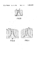
- FIGS. 3-8 are cross-section illustrations of the first through sixth steps, respectively, of the process for producing the insert illustrated in FIG. 1;
- FIG. 9 is a cross-section illustration of a wear-resistant annular insert produced in accordance with a second embodiment of the present invention.
- FIGS. 10-15 are cross-section illustrations of the first through sixth steps, respectively, of the process for producing the insert illustrated in FIG. 9.
- the wear-resistant annular insert 10 in accordance with the first embodiment of the invention is comprised of an annular, bi-layer construction including exterior layer 12 and interior layer 14 configured so as to provide a wide entry port 16 and a more narrow exit port 18.
- Exterior layer 12 is configured to provide an overall cylindrical shape to the insert, the upper portion of the exterior layer providing shoulder 20.
- the interior and exterior layers 14 and 12, respectively, correspond to the first and second dispersions produced according to the press and treat technique described in the above-mentioned pending patent applications.
- the interior layer is formed from a first dispersion of super-hard crystals, such as diamond or cubic boron nitride crystals, in carbon black
- the exterior layer is formed from a second dispersion of carbon black, carbon fiber and filler material.
- the first and second dispersions are individually mixed with a small amount of paraffin to lend a sufficient green strength to the two layers upon cold compaction thereof. After compacting the layers 12 and 14 together in the configuration as illustrated in FIG. 1 (or as shown in FIG.
- the compact is vacuum heated in the presence of silicon to burn off the paraffin and to allow the silicon to infiltrate both dispersions.
- the silicon reacts with the carbon black to form a ⁇ -silicon carbide and silicon matrix which bonds layers both internally and to each other.
- the insert illustrated in FIG. 1 is so configured as to reduce the volume of the interior layer to a minimum in order to accordingly reduce the amount of diamond or cubic boron nitride material which must be employed in the insert. By doing so, the cost of the insert is substantially reduced, while at the same time obtaining the benefits accorded through the use of such crystal material.
- FIG. 2 illustrates a reliable technique for mounting the insert 10.
- Insert 10 is disposed within tungsten carbide ring 22, shoulder 20 abutting tungsten carbide ring 22 at annular seat 24.
- the insert 10 and tungsten carbide ring 22 are maintained within annular holder 26 by ring mount 28. Mounting the insert in such a manner reduces vibration during operation of the device in order to obtain a high quality product.
- the insert 10, FIG. 9 (discussed in detail below) may be mounted in a similar manner.
- the mixture 30 of carbon black, carbon fiber, filler material and paraffin (the "second" dispersion described above), which mixture will eventually become exterior layer 12, is loaded into the void provided between annular mold 32 and cores 34 and 36, the alignment of cores 34 and 36 being provided by pin 38.
- the mold 32 and associated apparatus may be mounted on an annular base block 40 having height h, core 34 having a base portion 42 of a corresponding height.
- core 36 is removed and a plunger 44 is pressed onto the top of core 34 in order to softly compress mixture 30 into an intermediate compact.
- Plunger 44 is also provided with a base 46 having the same height h.
- the mold is then inverted to place plunger 44 on the bottom, and core 34 may be removed as shown in FIG. 5.
- Core 48 may then be placed inside the mold, core 48 being provided with an annular seat 50 which abuts the softly compressed mixture 30, as shown in FIG. 6.
- the mold is again inverted and mixture 52, of super-hard crystals and carbon black in paraffin (the "first" dispersion described above), which will eventually form interior layer 14, is loaded into the void provided between core 48 and mixture 30, as shown in FIG. 7.
- annular plunger 54 having a forward-jutting rim 54 along the interior circumference thereof, is forced down over core 48 to thereby tightly compact mixtures 30 and 52 to form a physically stable composite compact.
- the composite compact is then removed from the mold and the shoulder 20, FIG. 1, is soft-formed prior to sintering.
- the compact is then vacuum heated in the presence of silicon to burn off the paraffin and to allow the silicon to infiltrate both mixtures, as more fully explained in co-pending U.S. patent applications Ser. Nos. 167,019 and 167,196.
- the silicon reacts with the carbon black to form a ⁇ -silicon carbide and silicon matrix which bonds both mixtures both internally and to each other to form the interior and exterior layers 14 and 12, respectively, as shown in FIG. 1.
- FIG. 9 illustrates a second embodiment of the present invention which provides an insert 10, having a slightly more contoured internal surface than insert 10, FIG. 1.
- FIGS. 10-15 The process for producing the insert illustrated in FIG. 9 will now be described with further reference to FIGS. 10-15.
- the main difference between the process illustrated in FIGS. 10-15 and that illustrated in FIGS. 3-8 is the order in which the interior and exterior layers are formed.
- the exterior layer 12 is first formed as an intermediate compact, layer 14 further compacted onto layer 12, while in the process illustrated in FIGS. 10-15, the interior layer 14' is formed first, exterior layer 12' being compressed onto layer 14'.
- carbide core 58 is placed within annular carbide mold 60.
- An annular steel plunger 62 is placed on top of carbide core 58 in abutting relation thereto.
- the mixture 52 of diamond or cubic boron nitride crystals in carbon black in paraffin is loaded into the void provided between carbide core 58 and steel plunger 62 as shown.
- Annular plunger 64 is then placed over the upper end of carbide core 58 to compress mixture 52 fo form an intermediate composite as shown in FIG. 11.
- the compressed composite of mixtures 30 and 52 is removed from mold 60 along with carbide core 58 and plunger 64 as illustrated in FIG. 14, and conventionally subjected to an isostatic pressing in an elastic envlope (not shown).
- the isostatic pressing may also be provided in the production of the FIG. 1 embodiment as well, if desired.
- the compressed composite is then removed from carbide core 58 and placed on core 68 made from hexagonal boron nitride, as illustrated in FIG. 15.
- the composite and core 68 may then be placed within container 70, and centrally disposed therein by means of annular seat 72 for the vacuum heating, silicon infiltration, and sintering steps as disclosed in the above-mentioned co-pending application Ser. Nos. 167,019 and 167,196.
- container 70 is made of graphite, the inside thereof should be coated with hexagonal boron nitride paint.
- the wear-resistant annular inserts illustrated in FIGS. 1 or 9 may be produced using the inexpensive press and treat technique described in the above-mentioned co-pending applications.
- the inserts produced in accordance with such technique provide a very high degree of wear-resistance, are relatively inexpensive since the crystal material is localized only in critical areas and may be produced in large volumes using mass production techniques.
Abstract
Description
Claims (7)
Priority Applications (2)
| Application Number | Priority Date | Filing Date | Title |
|---|---|---|---|
| US06/331,369 US4483892A (en) | 1981-12-16 | 1981-12-16 | Wear resistant annular insert and process for making same |
| CA000417909A CA1199781A (en) | 1981-12-16 | 1982-12-16 | Nitrided superhard composite material |
Applications Claiming Priority (1)
| Application Number | Priority Date | Filing Date | Title |
|---|---|---|---|
| US06/331,369 US4483892A (en) | 1981-12-16 | 1981-12-16 | Wear resistant annular insert and process for making same |
Publications (1)
| Publication Number | Publication Date |
|---|---|
| US4483892A true US4483892A (en) | 1984-11-20 |
Family
ID=23293659
Family Applications (1)
| Application Number | Title | Priority Date | Filing Date |
|---|---|---|---|
| US06/331,369 Expired - Fee Related US4483892A (en) | 1981-12-16 | 1981-12-16 | Wear resistant annular insert and process for making same |
Country Status (1)
| Country | Link |
|---|---|
| US (1) | US4483892A (en) |
Cited By (7)
| Publication number | Priority date | Publication date | Assignee | Title |
|---|---|---|---|---|
| EP0197790A2 (en) * | 1985-04-09 | 1986-10-15 | De Beers Industrial Diamond Division (Proprietary) Limited | Wire drawing die |
| EP0437830A1 (en) * | 1990-01-16 | 1991-07-24 | General Electric Company | CVD diamond coated annulus components and method of their fabrication |
| EP0734797A3 (en) * | 1995-03-28 | 1997-07-02 | Gen Electric | Wire drawing die |
| WO2002006681A1 (en) * | 2000-07-13 | 2002-01-24 | Caldera Engineering, Lc | Flash tube device |
| FR2850116A1 (en) * | 2002-12-02 | 2004-07-23 | Alesages Diamant Carbure Adc | Reactor for diamond synthesis assisted by microwave plasma has system for forcing and depositing diamond germination species on inner walls of holes in wire drawing dies |
| US20100203341A1 (en) * | 2007-07-17 | 2010-08-12 | David Patrick Egan | Method for joining sic-diamond |
| CN104607490A (en) * | 2015-03-03 | 2015-05-13 | 株洲力洲硬质合金有限公司 | Processing process of micropore hard alloy wire-drawing mould |
Citations (18)
| Publication number | Priority date | Publication date | Assignee | Title |
|---|---|---|---|---|
| US2938807A (en) * | 1957-08-13 | 1960-05-31 | James C Andersen | Method of making refractory bodies |
| US3816081A (en) * | 1973-01-26 | 1974-06-11 | Gen Electric | ABRASION RESISTANT CEMENTED TUNGSTEN CARBIDE BONDED WITH Fe-C-Ni-Co |
| US4018631A (en) * | 1975-06-12 | 1977-04-19 | General Electric Company | Coated cemented carbide product |
| US4063909A (en) * | 1974-09-18 | 1977-12-20 | Robert Dennis Mitchell | Abrasive compact brazed to a backing |
| US4124401A (en) * | 1977-10-21 | 1978-11-07 | General Electric Company | Polycrystalline diamond body |
| US4151686A (en) * | 1978-01-09 | 1979-05-01 | General Electric Company | Silicon carbide and silicon bonded polycrystalline diamond body and method of making it |
| GB2006733A (en) * | 1977-10-21 | 1979-05-10 | Gen Electric | Bonded polycrystalline diamond body-silicon carbide or silicon nitride substrate composite |
| US4167399A (en) * | 1977-10-21 | 1979-09-11 | General Electric Company | Process for preparing a polycrystalline diamond body |
| US4173614A (en) * | 1977-10-21 | 1979-11-06 | General Electric Company | Process for preparing a polycrystalline diamond body/silicon nitride substrate composite |
| EP0010257A1 (en) * | 1978-10-24 | 1980-04-30 | General Electric Company | Polycrystalline diamond and/or cubic boron nitride body and method for producing same |
| EP0012966A1 (en) * | 1978-12-29 | 1980-07-09 | General Electric Company | Integral composite of polycristalline diamond and/or cubic boron nitride body phase and substrate phase and process for making it |
| US4219339A (en) * | 1977-03-03 | 1980-08-26 | Wilson William I | Diamond and cubic boron nitride abrasive compacts and conglomerates |
| US4220677A (en) * | 1976-01-30 | 1980-09-02 | Institut Sverkhtverdykh Materialov Akademii Nauk Ukrainskoi Ssr | Polycrystalline superhard material and method of producing thereof |
| US4238433A (en) * | 1978-12-15 | 1980-12-09 | General Electric Company | Method of making molten silicon infiltration reaction products |
| US4242106A (en) * | 1979-01-02 | 1980-12-30 | General Electric Company | Composite of polycrystalline diamond and/or cubic boron nitride body/silicon carbide substrate |
| US4247304A (en) * | 1978-12-29 | 1981-01-27 | General Electric Company | Process for producing a composite of polycrystalline diamond and/or cubic boron nitride body and substrate phases |
| US4248606A (en) * | 1979-08-23 | 1981-02-03 | General Electric Company | Supported diamond |
| US4268582A (en) * | 1979-03-02 | 1981-05-19 | General Electric Company | Boride coated cemented carbide |
-
1981
- 1981-12-16 US US06/331,369 patent/US4483892A/en not_active Expired - Fee Related
Patent Citations (19)
| Publication number | Priority date | Publication date | Assignee | Title |
|---|---|---|---|---|
| US2938807A (en) * | 1957-08-13 | 1960-05-31 | James C Andersen | Method of making refractory bodies |
| US3816081A (en) * | 1973-01-26 | 1974-06-11 | Gen Electric | ABRASION RESISTANT CEMENTED TUNGSTEN CARBIDE BONDED WITH Fe-C-Ni-Co |
| US4063909A (en) * | 1974-09-18 | 1977-12-20 | Robert Dennis Mitchell | Abrasive compact brazed to a backing |
| US4018631A (en) * | 1975-06-12 | 1977-04-19 | General Electric Company | Coated cemented carbide product |
| US4220677A (en) * | 1976-01-30 | 1980-09-02 | Institut Sverkhtverdykh Materialov Akademii Nauk Ukrainskoi Ssr | Polycrystalline superhard material and method of producing thereof |
| US4219339A (en) * | 1977-03-03 | 1980-08-26 | Wilson William I | Diamond and cubic boron nitride abrasive compacts and conglomerates |
| US4124401A (en) * | 1977-10-21 | 1978-11-07 | General Electric Company | Polycrystalline diamond body |
| US4167399A (en) * | 1977-10-21 | 1979-09-11 | General Electric Company | Process for preparing a polycrystalline diamond body |
| US4173614A (en) * | 1977-10-21 | 1979-11-06 | General Electric Company | Process for preparing a polycrystalline diamond body/silicon nitride substrate composite |
| GB2006733A (en) * | 1977-10-21 | 1979-05-10 | Gen Electric | Bonded polycrystalline diamond body-silicon carbide or silicon nitride substrate composite |
| US4151686A (en) * | 1978-01-09 | 1979-05-01 | General Electric Company | Silicon carbide and silicon bonded polycrystalline diamond body and method of making it |
| EP0010257A1 (en) * | 1978-10-24 | 1980-04-30 | General Electric Company | Polycrystalline diamond and/or cubic boron nitride body and method for producing same |
| US4220455A (en) * | 1978-10-24 | 1980-09-02 | General Electric Company | Polycrystalline diamond and/or cubic boron nitride body and process for making said body |
| US4238433A (en) * | 1978-12-15 | 1980-12-09 | General Electric Company | Method of making molten silicon infiltration reaction products |
| EP0012966A1 (en) * | 1978-12-29 | 1980-07-09 | General Electric Company | Integral composite of polycristalline diamond and/or cubic boron nitride body phase and substrate phase and process for making it |
| US4247304A (en) * | 1978-12-29 | 1981-01-27 | General Electric Company | Process for producing a composite of polycrystalline diamond and/or cubic boron nitride body and substrate phases |
| US4242106A (en) * | 1979-01-02 | 1980-12-30 | General Electric Company | Composite of polycrystalline diamond and/or cubic boron nitride body/silicon carbide substrate |
| US4268582A (en) * | 1979-03-02 | 1981-05-19 | General Electric Company | Boride coated cemented carbide |
| US4248606A (en) * | 1979-08-23 | 1981-02-03 | General Electric Company | Supported diamond |
Cited By (11)
| Publication number | Priority date | Publication date | Assignee | Title |
|---|---|---|---|---|
| EP0197790A2 (en) * | 1985-04-09 | 1986-10-15 | De Beers Industrial Diamond Division (Proprietary) Limited | Wire drawing die |
| EP0197790A3 (en) * | 1985-04-09 | 1988-09-28 | De Beers Industrial Diamond Division (Proprietary) Limited | Wire drawing die |
| US4872333A (en) * | 1985-04-09 | 1989-10-10 | Burnand Richard P | Wire drawing die |
| EP0437830A1 (en) * | 1990-01-16 | 1991-07-24 | General Electric Company | CVD diamond coated annulus components and method of their fabrication |
| EP0734797A3 (en) * | 1995-03-28 | 1997-07-02 | Gen Electric | Wire drawing die |
| WO2002006681A1 (en) * | 2000-07-13 | 2002-01-24 | Caldera Engineering, Lc | Flash tube device |
| US6523573B2 (en) * | 2000-07-13 | 2003-02-25 | Caldera Engineering, Lc | Flash tube device |
| FR2850116A1 (en) * | 2002-12-02 | 2004-07-23 | Alesages Diamant Carbure Adc | Reactor for diamond synthesis assisted by microwave plasma has system for forcing and depositing diamond germination species on inner walls of holes in wire drawing dies |
| US20100203341A1 (en) * | 2007-07-17 | 2010-08-12 | David Patrick Egan | Method for joining sic-diamond |
| US8757472B2 (en) | 2007-07-17 | 2014-06-24 | David Patrick Egan | Method for joining SiC-diamond |
| CN104607490A (en) * | 2015-03-03 | 2015-05-13 | 株洲力洲硬质合金有限公司 | Processing process of micropore hard alloy wire-drawing mould |
Similar Documents
| Publication | Publication Date | Title |
|---|---|---|
| US4260397A (en) | Method for preparing diamond compacts containing single crystal diamond | |
| US4470953A (en) | Process of manufacturing sintered metallic compacts | |
| DE3169121D1 (en) | Diamond and cubic boron nitride abrasive compacts using size selective abrasive particle layers and process for making same | |
| US4483892A (en) | Wear resistant annular insert and process for making same | |
| US4448591A (en) | Cutting insert having unique cross section | |
| US4082559A (en) | Cemented carbide products and manufacturing method | |
| CA1185776A (en) | Indexable composite cutting insert having corner cutting edges | |
| US4164527A (en) | Method of making superhard articles | |
| JPH0260632B2 (en) | ||
| US3173314A (en) | Method of making core drills | |
| US4544517A (en) | Automatic composite press technique for producing cutting inserts | |
| US4453951A (en) | Process for the production of silicone carbide composite | |
| EP0081775B1 (en) | Nitrided superhard composite material | |
| US4353963A (en) | Process for cementing diamond to silicon-silicon carbide composite and article produced thereby | |
| EP0212872A2 (en) | Method and apparatus for forming shaped pieces of insulation | |
| US4417906A (en) | Process for production of silicon carbide composite | |
| EP0056596A1 (en) | Improved silicon carbide composite and process for production | |
| US2766565A (en) | Metal bonded abrasive wheel and method of making the same | |
| US5016498A (en) | Method and apparatus for manufacturing super abrasive cutting saw | |
| JPH0515367Y2 (en) | ||
| US4428755A (en) | Process for the production of silicone carbide composite | |
| US2332071A (en) | Manufacture of hard rollers | |
| EP0043542B1 (en) | Process for production of a silicon carbide composite | |
| CA1171666A (en) | Process for cementing diamond to silicon-silicon carbide composite and article produced thereby | |
| US4497639A (en) | Silicon carbide cutting insert with pre-pressed core center piece and sintered diamond envelope |
Legal Events
| Date | Code | Title | Description |
|---|---|---|---|
| AS | Assignment |
Owner name: GENERAL ELECTRIC COMPANY, A CORP. OF NY. Free format text: ASSIGNMENT OF ASSIGNORS INTEREST.;ASSIGNOR:OHNO, JOHN M.;REEL/FRAME:003957/0712 Effective date: 19811204 Owner name: GENERAL ELECTRIC COMPANY, NEW YORK Free format text: ASSIGNMENT OF ASSIGNORS INTEREST;ASSIGNOR:OHNO, JOHN M.;REEL/FRAME:003957/0712 Effective date: 19811204 |
|
| AS | Assignment |
Owner name: CARBOLOY INC., A DE. CORP. Free format text: ASSIGNMENT OF ASSIGNORS INTEREST.;ASSIGNOR:GENERAL ELECTRIC COMPANY;REEL/FRAME:004811/0365 Effective date: 19870925 |
|
| FEPP | Fee payment procedure |
Free format text: PAYER NUMBER DE-ASSIGNED (ORIGINAL EVENT CODE: RMPN); ENTITY STATUS OF PATENT OWNER: LARGE ENTITY Free format text: PAYOR NUMBER ASSIGNED (ORIGINAL EVENT CODE: ASPN); ENTITY STATUS OF PATENT OWNER: LARGE ENTITY |
|
| FPAY | Fee payment |
Year of fee payment: 4 |
|
| REMI | Maintenance fee reminder mailed | ||
| LAPS | Lapse for failure to pay maintenance fees | ||
| FP | Lapsed due to failure to pay maintenance fee |
Effective date: 19921122 |
|
| STCH | Information on status: patent discontinuation |
Free format text: PATENT EXPIRED DUE TO NONPAYMENT OF MAINTENANCE FEES UNDER 37 CFR 1.362 |