US4482068A - Child resistant safety cap - Google Patents
Child resistant safety cap Download PDFInfo
- Publication number
- US4482068A US4482068A US06/547,107 US54710783A US4482068A US 4482068 A US4482068 A US 4482068A US 54710783 A US54710783 A US 54710783A US 4482068 A US4482068 A US 4482068A
- Authority
- US
- United States
- Prior art keywords
- ring
- cap
- locking groove
- closure
- outwardly directed
- Prior art date
- Legal status (The legal status is an assumption and is not a legal conclusion. Google has not performed a legal analysis and makes no representation as to the accuracy of the status listed.)
- Expired - Fee Related
Links
Images


Classifications
-
- B—PERFORMING OPERATIONS; TRANSPORTING
- B65—CONVEYING; PACKING; STORING; HANDLING THIN OR FILAMENTARY MATERIAL
- B65D—CONTAINERS FOR STORAGE OR TRANSPORT OF ARTICLES OR MATERIALS, e.g. BAGS, BARRELS, BOTTLES, BOXES, CANS, CARTONS, CRATES, DRUMS, JARS, TANKS, HOPPERS, FORWARDING CONTAINERS; ACCESSORIES, CLOSURES, OR FITTINGS THEREFOR; PACKAGING ELEMENTS; PACKAGES
- B65D50/00—Closures with means for discouraging unauthorised opening or removal thereof, with or without indicating means, e.g. child-proof closures
- B65D50/02—Closures with means for discouraging unauthorised opening or removal thereof, with or without indicating means, e.g. child-proof closures openable or removable by the combination of plural actions
- B65D50/06—Closures with means for discouraging unauthorised opening or removal thereof, with or without indicating means, e.g. child-proof closures openable or removable by the combination of plural actions requiring the combination of different actions in succession
- B65D50/061—Closures with means for discouraging unauthorised opening or removal thereof, with or without indicating means, e.g. child-proof closures openable or removable by the combination of plural actions requiring the combination of different actions in succession being disengageable from container only after rotational alignment of closure, or other means inhibiting removal of closure, with container, e.g. tortuous path type
- B65D50/062—Closures with means for discouraging unauthorised opening or removal thereof, with or without indicating means, e.g. child-proof closures openable or removable by the combination of plural actions requiring the combination of different actions in succession being disengageable from container only after rotational alignment of closure, or other means inhibiting removal of closure, with container, e.g. tortuous path type the closure removal inhibiting means being a displaceable ring
Definitions
- This invention relates to safety closures for containers and has particular reference to closures including a snap-on cap and safety ring. These closures are frequently called child resistant closures because they tend to prevent children from readily opening the containers.
- the safety closures disclosed in U.S. Pat. Nos. 3,612,322 and 3,693,820 comprise a snap-on cap held in place on a container by a rotary safety ring which must be aligned with the cap in one angular position and pushed downwardly away from the cap before one can remove the cap from the container.
- the ring is locked around a portion of the cap by fingers, which extend either from the inside of the ring or from the cap, and which fingers fit into a locking groove formed between the ring and cap.
- the ring is unlocked by aligning it with the cap in one angular position so that the fingers slide through release grooves in the locking groove when the ring is pulled downwardly away from the cap. Then the cap can be removed.
- the present invention improves the prior closures by, for instance, providing an outwardly directed bead on the safety ring which makes it easier to grip and push down (and up) the safety ring.
- this invention discloses an annular protrusion projecting from the underside of the cap which protrusion closely abuts the rim of the container so that the protrusion and rim act as a liquid-tight seal.
- the seal of the bottle is further improved by a circumferential knob around the neck of the container. The knob prevents the safety ring, and hence the cap locked thereto, from moving upwardly, thereby keeping the annular protrusion close to the rim.
- the present invention provides a safety closure of the general type described above having an annular protrusion which projects from the underside of the cap and which has a diameter slightly less than the inside diameter of the rim of the container.
- This protrusion made so that it closely abuts the rim of the container when the cap is securely closed, and the rim of the container make a liquid-tight seal; that is, liquid cannot flow through the seal.
- This invention also improves the seal of the container by providing a circumferential knob around the neck of the container. The knob keeps the annular protrusion closely abutted to the rim of the container by preventing upward movement of the safety ring and cap assembly. The knob engages a portion of the safety ring when the ring is locked around the cap.
- Another feature of the present invention provides an outwardly directed bead on the outside of the safety ring. When one grabs the ring, the bead will protrude into one's finger and make it easier to push the ring up or down.
- This invention improves the safety closures described in the prior art by disclosing a safety ring which extends up to the top of the cap so that there is no lateral opening between the safety ring and the cap.
- This invention also provides various counters to count the number of uses or doses of the container's contents.
- These counters located on the safety ring of the general type described above, include at least one set of numbers appearing around the outside of the safety ring. Any one of these numbers can be aligned with an indicia of position on a cylindrical strap surrounding the safety ring. Alternatively, any one of these numbers can be aligned with any number from a second set of numbers appearing around a cylindrical strap surrounding the safety ring.
- this invention discloses specific embodiments of these features. Two such embodiments, a safety closure for a powder container with a sifter inserted in the mouth of the container, and a pipette dropper safety closure, show the various features of this invention.
- FIG. 1 is a perspective view of the safety closure of this invention on a container and shows the ring locked on the cap.
- FIG. 2 is a perspective view of the safety closure, equipped with a safety ring for counting the number of uses or doses of the container's contents, of this invention on a container and shows the ring locked on the cap.
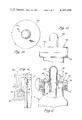
- FIG. 3 shows a cross-sectional view of the safety ring, taken along the line 3--3 of FIG. 1.
- FIG. 4 shows a top view of the cap and safety ring in an angular position from which the ring can not be moved downwardly away from the cap; the ring and cap are locked together.
- FIG. 5 is an enlarged fragmentary view, partly in cutaway section, taken along the lines 5--5 of FIG. 4.
- FIG. 5 shows the ring locked on the cap.
- FIG. 6, taken along lines 6--6 of FIG. 5, shows an enlarged cross-sectional view of the safety closure, including the safety ring, cap, and the neck of the container.
- FIG. 7 an enlarged vertical cross-sectional view of the safety closure, shows the cap and safety ring aligned in the one angular position from which the ring can be moved downwardly away from the cap.
- the tab 19 of the ring and the fingers 26 of the cap are overlapping (i.e., aligned).
- FIG. 8 shows the ring fastened to the cap.
- FIG. 9 is an enlarged perspective view of the underside of the cap.
- FIG. 10 is an enlarged view of the safety closure equipped with a safety ring for counting the number of uses or doses of the container's contents.
- FIG. 11 is an enlarged view of the safety closure shown in FIG. 10, taken along the line 11--11 of FIG. 10.
- the cap and safety ring, but not the neck of the container, are shown in a cross-sectional view.
- FIG. 12 shows an enlarged view of the safety closure equipped with a safety ring for counting the number of uses or doses of the container's contents in a particular day.
- FIG. 13 is an enlarged fragmentary view of the safety closure shown in FIG. 12, taken along the line 13--13 of FIG. 12.
- the cap and safety ring, but not the neck of the container, are shown in a cross-sectional view.
- FIG. 14 shows a top view of the pipette dropper safety closure.
- FIG. 15 shows a side view of the pipette dropper safety closure.
- FIG. 16 is an enlarged vertical cross-sectional view of the pipette dropper safety closure; FIG. 16 is taken along line 16--16 of FIG. 17.
- FIG. 17 shows an enlarged cross-sectional view of the pipette dropper safety closure.
- FIG. 18 shows a top view of the safety closure for powder bottles.
- FIG. 19 shows a top view of the safety closure for powder bottles; the cap has been removed.
- FIG. 20 shows an enlarged cross-sectional view of the safety closure for powder bottles.
- FIG. 21 shows an enlarged cross-sectional view of the safety closure, with the cap attached to the bottle, for powder bottles.
- FIG. 22 is an enlarged fragmentary view, partly in cutaway section. It shows the upper end of the ring being substantially even with the top of the cap.
- the present invention embodied in a new and improved safety closure for a container, is illustrated in the exemplary drawings.
- the safety closure 5 designed for a container 7 having a neck 9 and a rim 10 defining an open mouth, generally comprises a flexible, snap-on cap (“cap”) 12 covering the mouth of the container and a rotary safety ring (“safety ring”) 14, which holds the cap on the container when the ring overlies a portion of the cap.
- Longitudinal (and longitudinally), as used to describe and claim this invention, means along the length of the container; that is, along a line extending from the cap, through the ring and down through the neck to the bottom of the container. This line is, of course, a vertical line when the container sits normally on its bottom on a flat surface.
- lateral (and laterally), as used to describe and claim this invention means along the width of the container; that is, along a line extending from one point of the cap, or ring, or container, to a diametrically opposed point on the cap, ring or container, respectively. These lines are horizontal when the container sits normally.
- the term “container” includes glass bottles, paper containers, molded plastic containers (e.g., thermoplastic, thermosetting and laminated plastic bottles), metal containers and similar containers having a neck and a rim defining an open mouth.
- the cap 12 has a top 13 overlying the rim 10 of the container 7 and a depending annular flange (depending flange or depending annular flange member) 15 which projects downwardly from the top and surrounds an upper portion of the neck 9.
- An outwardly projecting radial flange 16 is the portion of the top which extends beyond the depending annular flange member 15.
- Near the lower end of the depending flange 15 is an inwardly directed circumferential bead 17 which engages a peripheral lip 18 surrounding the rim 10 when the cap is secured to the container.
- the peripheral lip 18 projects outwardly around the rim of the container and, together with the inwardly directed circumferential bead 17 of the depending flange 15, forms an interfitting means between the cap and the container.
- the cap 12 is attached to the container 7 by pressing the cap downwardly over the rim 10, which causes the depending flange 15 to flex outwardly to allow the inwardly directed circumferential bead 17 to slip over the peripheral lip 18 of the container and then to flex inwardly back to its original position, where it engages the peripheral lip 18.
- the safety ring 14 normally surrounds the depending annular flange 15 to block outward flexing of the depending flange, and thereby prevents the inwardly directed circumferential bead 17 from slipping over the peripheral lip 18 when one attempts to lift the cap 12. Vertical serrations completely around the safety ring 14 may be added to make it easier to grip the ring.
- the safety ring 14 generally has an L-shaped vertical cross section, as shown in FIG. 6.
- the tab 19 of the safety ring as shown in FIGS. 1 and 3 forms the outwardly projecting lateral wall 20 of the safety ring which appears in FIGS. 5 and 6.
- the section as shown in FIG. 6.
- the tab 19 of the safety ring as shown in FIGS.
- the generally L-shaped vertical cross-section of the safety ring is formed by an annular sidewall 23 and an inwardly projecting bottom wall 24 which extends to the neck 9 of the container 7.
- the sidewall 23 encircles the depending flange 15 of the cap when the closure is locked, and the bottom wall 24 strengthens the sidewall and assists in positioning the safety ring on the container.
- the bottom wall 24 also prevents the safety ring from sliding off the neck of the container by engaging the peripheral lip 18 when the safety ring slides down the neck, as it does when the container is tilted to remove the container's contents.
- an upwardly projecting flange 25 may be provided on the inner end of the bottom wall to help keep the safety ring around the neck of the container. This invention discloses below another use of this flange.
- the safety ring 14 To release the cap 12 for removal from the container 7, the safety ring 14 must be precisely aligned in a preselected angular position relative to the cap 12.
- the tab 19 of the safety ring and the finger 26 of the cap can be used to indicate when the safety ring is precisely aligned in the preselected angular position relative to the cap.
- the safety ring 14 When the finger 26 overlaps the tab 19, as shown in FIG. 7, the safety ring 14 is precisely aligned with the cap 12, so that the safety ring can be pushed downwardly away from the cap.
- the safety ring can be pushed downwardly away from the cap only when the ring is precisely aligned with the cap.
- the safety ring 14 of the containers shown in FIG. 1, 2, 4, 5 and 6, being misaligned with the cap 12 cannot not be pushed downwardly away from the cap.
- these containers are "locked”; that is, the safety ring is locked around the cap.
- an indentation rather than a finger, may be used in the cap.
- an indentation 8 in the cap 12 provides a convenient way to align the cap 12 and ring 14.
- the indentation 8 in the cap 12 is the preferred embodiment of the invention because a cap with a finger 26 can be more easily forced off the container (by inserting a sharp object between the finger and the top of the ring) than a cap with an indentation.
- the cap 12 can be lifted off the container 7 since the depending flange 15 is now free to flex outwardly. As one pulls the cap up, the outward flexion of the depending flange 15 permits the inwardly directed circumferential bead 17 to slip around the peripheral lip 18.
- the cap 12 is pressed back onto the neck 9, so that the inwardly directed circumferential bead 17 slips around and under the peripheral lip 18.
- the safety ring is raised back into the locked position so that the annular sidewall 23 encircles the depending flange 15 of the cap 12.
- the safety ring can be raised back into the locked position in any angular position with the cap; no alignment of cap and safety ring is necessary.
- the safety ring locks around the depending flange by at least one, and preferably several, resiliently flexible fingers 30 which may be angularly spaced about the inside of the annular sidewall 23.
- the safety ring shown in FIG. 3 has eight such fingers 30.
- the angularly spaced, flexible fingers 30, connected at one end to the inside of the annular sidewall 23 of the safety ring 14, project inwardly into a circumferential locking groove 31 formed around the depending flange 15 of the cap 12 to lock the ring in position around the cap.
- the locking groove 31 is defined by an outwardly directed circumferential bead 32 located near the bottom of the depending flange 15, the outwardly projecting radial flange 16 of the top 13 and the longitudinal portion of the depending flange 15.
- the fingers 30 project inwardly into the locking groove 31 when the safety ring 14 is in place around the depending flange 5 and have free inner ends 33 which overlie an upwardly facing shoulder 34, which forms the bottom wall of the locking groove 31.
- the fingers 30 closely approach the longitudinal portion of the depending flange 15.
- the upwardly facing shoulder 34 defines the top of the outwardly directed circumferential bead 32.
- a number of longitudinally extending release grooves 35 are formed in the outer side of the depending flange 15 between the locking groove 31 and the lower end of the flange.
- the number of release grooves is equal to the number of fingers 30 on the safety ring.
- the depending flange 15, designed to work with the safety ring 14 depicted in FIG. 3 has eight release grooves 35.
- the release grooves 35 extend from the locking groove 31 through the upwardly facing shoulder 34 to the lower longitudinal end of the depending flange 15.
- the fingers 30 and the release grooves 35 are formed in a special manner to prevent downward movement of the ring except in one angular position of the ring with regard to the cap, thus limiting the release of the cap to that one position.
- the fingers 30 and associated release grooves 35 are of different sizes so that the ring 14 is releasable in only one angular position.
- Each of the release grooves 35 is to be aligned with a particular finger, which alignment occurs in the one preselected angular position (when, as noted above, the finger 26 of the top 13 overlaps the tab 19 of the safety ring).
- Each of the release grooves 35 is slightly larger than its associated finger 30 and, when properly aligned with the finger, will permit it to slide from the locking groove 31 through the release grooves 35 in the outwardly directed circumferential bead 32 and off the cap 12.
- the cap can be pulled off the container 7 to allow dispensing of its contents.
- the cap is snapped over the rim 10, and the ring 14 is pushed upwardly into position around the depending flange 15. Since the fingers 30 are flexible and inclined inwardly and have an upper edge 37 which is inclined downwardly, no prealignment of the fingers and the release grooves 35 is necessary.
- the safety ring 14 is moved upwardly with the fingers 30 out of alignment with their release grooves 35, the outwardly directed circumferential bead 32 of the depending flange 15 deflects the fingers 30 and annular sidewall 23 of the safety ring outwardly.
- the fingers 30, as illustrated in FIGS. 3, 5 and 6, have generally rectangular cross-sections and are integrally joined to the safety ring 14.
- a plurality of recesses may be formed in the annular sidewall, such recesses being aligned with the fingers to receive them substantially flush with the annular sidewall as the safety ring is move back upwardly onto the cap.
- the fingers may be formed as cutouts from the annular sidewall 23 of the safety ring 14, such cutouts being integrally joined to the safety ring at their upper ends, and a plurality of recesses being formed from the spaces from which the fingers were cut.
- the fingers 30 can be formed on the cap and the grooves in the ring. In this latter situation, the fingers 30 will be inclined outwardly and upwardly from the cap 12 and the release grooves 35 will extend from the locking groove 31 upwardly to the upper end of the annular sidewall 23 of the safety ring. In either case, the fingers can be formed and set in the extended condition by conventional plastic molding techniques.
- this invention provides an outwardly directed bead 38 on the outside of the annular sidewall 23 of the safety ring 14.
- the bead 38 allows one to more easily grip and move the safety ring 14; removing the safety ring from the cap and replacing the safety ring onto the cap are much easier with the bead 38 than without it.
- the word "bead,” as used to describe and claim this element of the present invention, means any protrusion, regardless of the shape of its vertical cross-section, which provides a means for gripping the safety ring 14.
- the bead could have a rectangular, triangular or circular vertical cross-section; all such beads are included within the term "bead”.
- the outwardly directed bead 38, illustrated in FIGS. 5 and 6, has a roughly circular vertical cross-section because such a shape is gentler on one's fingers.
- the outwardly directed bead 38 is located at the lower end of the annular sidewall 23 of the safety ring 14, as illustrated in FIGS. 5 and 6, and surrounds the entire annular sidewall 23.
- the bead 38 in order to function, need not surround the entire annular sidewall 23; for example, it may extend only around most of the sidewall.
- four separate outwardly directed beads 38 each located in a quadrant of the annular sidewall 23 and each extending only around a portion of its quadrant, may be provided. Similar arrangements of the bead 38 can be envisioned in accordance with this invention.
- the outwardly directed bead 38 should be made large enough so that it provides a sufficient grip for one's fingers when one pushes the safety ring 14 up or down, but it should not be so large that it makes the operation of the counters, described below, difficult.
- this invention provides an annular protrusion 40 which projects from the surface of the underside of the top 13.
- the annular protrusion 40 has an average diameter slightly less than the inside diameter of the rim 10 of the container 7.
- the annular protrusion 40 closely abuts the rim 10, thereby sealing the contents of the container. This seal tends to be liquid-tight and, of course, will help keep gases from flowing in and out of the container 7.
- the protrusion must form a complete circle if the rim 10 forms a complete circle. That is, whatever the shape of the rim 10 of the container 7, the annular protrusion 40 must, in order to operate according to this invention, have the same shape and fit tightly inside the rim 10.
- the annular protrusion 40 projects below the top far enough that it will closely abut the rim 10 when the cap 12 is pressed back onto the neck 9.
- the projection of the annular protrusion is about equal to the thickness of the top 13, as indicated by FIG. 6.
- the cap 12 is pressed back onto the neck 9 when the inwardly directed circumferential bead 17 slips around and under the peripheral lip 18.
- the annular protrusion 40 must be made so that it closely abuts the rim 10 when the inwardly directed circumferential bead 17 slips around and under the peripheral lip 18.
- the shape of the vertical cross-section of the annular protrusion 40 may be rectangular, triangular, circular or any other shape which would assure that the fit between the rim 10 and the annular protrusion 40 is liquid-tight.
- the annular protrusion 40 has a triangular vertical cross-section.
- this invention provides a circumferential knob 22 which keeps the annular protrusion 40 closely abutted to the rim 10 when the ring 14 is locked around the cap 12.
- This circumferential knob 22 is illustrated in, interalia, FIGS. 5 and 6.
- the cap 12 cannot be moved upwardly once the knob 22 wedges against the upwardly projecting radial flange 25.
- the knob 22 is positioned near the rim 10 of the container so that, as one pulls the cap up, the knob 22 wedges against the upwardly projecting radial flange 25 before the seal between the annular protrusion 40 and the rim 10 is destroyed.
- the knob 22 is located below the peripheral lip 18 of the container 7 and must be at least large enough, regardless of its shape, to block the flange 25.
- the circumferential knob 22 protects the seal, created by the annular protrusion 40 and the rim 10, from forceful attempts to open the container.
- This knob 22 is also important because the manufacturing tolerances of the cap, container, and ring sometimes cause the locked assembly (i.e., the cap and ring when the ring is locked around the cap) to move vertically, thereby affecting the liquid-tight seal.
- the cap 150 does not have an outwardly projecting radial flange 16 (shown in FIG. 6) superimposed over the ring 160.
- the cap 150 is substantially identical to the cap 12 described above.
- the cap 150 has an inwardly directed circumferential bead 17 which engages the peripheral lip 18 of the container 7 and has a depending flange 15.
- the ring 160 has an enlarged annular sidewall 161, corresponding to the annular sidewall 23 of the ring 14 described above (refer to FIG. 6 and accompanying description).
- the ring 160 is substantially identical to the ring 14 described above.
- the annular sidewall 161 extends up to the upper edge of the top 151 of the cap 150 so that the upper end 162 of the annular sidewall 161 is substantially even with the upper edge of the top 151. Thus, there is no lateral opening between the ring 160 and the cap 150 which could be used by a child attempting to open the container by forcing his fingers or teeth into such an opening.
- the upper end 162 should extend at least above the underside of the cap 150.
- FIGS. 10 and 11 show a safety closure 42 equipped with a counter 70 for counting the number of uses or doses of the container's contents.
- the safety closure 42 is structurally and functionally identical to the safety closure 5 described and illustrated above, except for the safety ring 43, which is modified for the counter 70.
- the counter 70 located on the safety ring 43, includes a set of numbers 71 appearing around the outside of the annular sidewall 44 of the safety ring 43 and a cylindrical strap 72 with a window-like aperture (“window”) 73 appearing thereon.
- the cylindrical strap 72 snugly surrounds the annular sidewall 44 and overlies the set of numbers 71 appearing around the outside of the annular sidewall 44.
- the set of numbers 71 are stationary, as they are fixed to the outside of the annular sidewall 44.
- the numbers in the set of numbers 71 are integers which appear sequentially around the annular sidewall "50", the latter number being determined largely by the size of the numbers and the size of the annular sidewall.
- the cylindrical strap 72 can be rotated around the annular sidewall 44, thereby allowing one to place the window-like aperture 73 in front of any number from the set of numbers 71.
- the cylindrical strap 72 is preferably made from opaque plastic, and an annular bar 74, with serrations 75 thereon to allow one to more easily grasp the bar, may be attached to the upper (or lower) end of the cylindrical strap 72 to make rotation of the strap easy.
- the cylindrical strap 72 may also be made from a transparent material, such as plastic, and the window-like aperture 73 may be marked or otherwise fixed on the cylindrical strap 72.
- the window-like aperture 73 consists of clear plastic or a rectangular opening in the opaque plastic of the cylindrical strap 72.
- the largest number from the set of numbers 71 is large enough, one could count the number of pills (or doses) or uses remaining in the container 7.
- the window-like aperture 73 which serves as an indication of position, could, in accordance with this invention, be replaced by other means for indicating a positon on the cylindrical strap 72.
- an arrow or notch appearing on the cylindrical strap which arrow or notch could be aligned with any number from the set of numbers 71, could be used as a means for indicating position.
- FIGS. 12 and 13 Another means for counting, illustrated in FIGS. 12 and 13, involves a safety closure 45 equipped with a counter 80 for counting the number of uses or doses of the container's contents in a particular day or other period of time.
- the safety closure 45 is structurally and functionally identical to the safety closure 5 described and illustrated above, except for the safety ring 46, which is modified for the counter 80.
- the counter 80 located on the safety ring 46, includes a first set of numbers 81 appearing around the outside of the annular sidewall 47 of the safety ring 46 and a cylindrical strap 82, on which appears a second set of numbers 83.
- the cylindrical strap 82 snugly surrounds the annular sidewall 47 and overlies the first set of numbers 81 appearing around the outside of the annular sidewall 47.
- the first set of numbers 81 are stationery, as they are fixed to the outside of the annular sidewall 47.
- the second set of numbers 83 are fixed on the cylindrical strap 82 and, hence, rotate with the cylindrical strap 82 when the strap is rotated.
- the second set of numbers 83 are molded on the outer wall of the cylindrical strap 82 and the first set of numbers 81 are molded on the annular sidewall 47; the plane defined by the first set of numbers 81 is fixed above the plane defined by the second set of numbers 83, and so, the first set of numbers 81 appears juxtaposed above the second set of numbers 83.
- the relationship of these two planes may be reversed so that the second set of numbers 83 appears juxtaposed above the first set of numbers 81.
- the first set of numbers 81 may be made in a particular color, and the second set of numbers 83 may be another color.
- the numbers in the first and second sets of numbers 81 and 83 appear sequentially around the annular sidewall 47 and cylindrical strap 82, respectively.
- the numbers in both sets 81 and 83 are integers which appear sequentially from “1" to about "50", the latter number being determined largely by the size of the numbers and the size of the annular sidewall 47 or cylindrical strap 82 (whichever the case may be).
- the numbers in the first set of numbers 81 are the integers "1" through "31", as shown in FIG. 12; these integers may be used to represent any day in any month.
- Each number in the second set of numbers 83 may be fixed within the perimeter of a rectangular, window-like marking 84 on the cylindrical strap 82.
- FIG. 12 shows only one such marking.
- the window-like marking 84 may be made large enough that the number from the first set of numbers 81, which appears juxtaposed longitudinally to the number from the second set of numbers 83, is included within the perimeter of the window-like marking 84.
- the cylindrical strap 82 can be rotated around the annular sidewall 47, thereby allowing one to place any number from the second set of numbers 83 in longitudinal juxtaposition with any number from the first set of numbers 81.
- the rectangular, window-like markings 84 the perimeter of which surrounds each number in the second set of numbers 83, may be used to verify that one particular number from the second set is longitudinally juxtaposed with a number from the first set.
- the cylindrical strap 82 is preferably made from clear plastic which fits snugly around the annular sidewall 47, yet not so snugly that the strap 82 is difficult to rotate; the strap 82 shown in FIGS.
- the cylindrical strap 82 To count the number of uses or doses of the container's contents in a particular day, one rotates the cylindrical strap 82 so that the number of doses taken (or uses) appears juxtaposed longitudinally with the date of the month. For example, if one has just taken the eighth dose for the second day of June, one places the number "8" from the second set of numbers 83, which appears below the first set of numbers 81 in this particular example, under the number "2" from the first set of numbers 81.
- the tab 19 on the safety ring 46 may be used as an indication of position, just as the window-like aperture 73 is used to indicate position on the counter described above; thus, using this tab 19, one can use the counter illustrated in FIGS. 12 and 13 as if it were the counter illustrated in FIGS. 10 and 11.
- letters may be used in lieu of numbers on the counters described herein.
- letters such as the alphabet, appearing around the safety ring 44, shown in FIG. 10, could be used to count the number of doses or uses of the container's contents.
- the size of the ring should be large enough so that the numbers can be read, but not so large as to make the ring difficult to work.
- FIGS. 14, 15, 16, and 17 show, the invention disclosed herein can be applied to other kinds of containers which accept the safety closures described herein.
- the safety closure 100 generally identical in structure and function to the safety closure 5 described above, appears on a pipette dropper container 101.
- the safety closure 100 is identical to the safety closure 5 described above ans shown in FIGS. 1, 5, 6, and 7 except that the cap 102 accepts a pipette dropper 103 or other means for drawing and holding fluid into a vessel.
- the pipette dropper 103 includes a squeezable bulb 104 and a pipette 105.
- the cap 102 has a circular hole 106 through which the squeezable bulb 104 passes.
- the pipette 105 when the closure is closed, usually extends from about the surface of the underside of the top 13 to almost the bottom of the container 101.
- the pipette 105 which may be glass, plastic or other materials capable of holding liquids, has an outwardly directed circumferential ridge 107 near its top which engages a circumferential channel 108 located near the bottom of the squeezable bulb 104.
- the ridge 107 and channel 108 are made so that the ridge 107 fits tightly within the channel 108 and, hence, the pipette is securely attached to the squeezable bulb 104.
- the squeezable bulb 104 extends from about 2 inches above the top 13 to about 1/2 inch below the underside of the top 13.
- the bulb 104 has thicker, less flexible walls 109 immediately around the area where it passes through the top 13 and where it engages the pipette 105.
- the bulb 104 is attached to the top 13 by a circular groove 110 in the bulb's thicker, less flexible walls 109; the edges of the circular hole 106 engage the circular groove so that the squeezable bulb 104 is tightly attached to the top.
- the squeezable bulb 104 is bonded to the cap 102 so that a child cannot pull it out of the cap.
- the circular groove 110 is located just above the circumferential channel 108.
- FIGS. 18, 19 20 and 21 show a further example of how the invention disclosed herein can be applied to other kinds of containers which accept the safety closures described herein.
- the safety closure 120 generally identical in structure and function to the safety closure 5 described above, appears on a powder container (that is, a container intended to hold and dispense powder).
- the safety closure 120 is identical to the safety closure 5 described above and shown in FIGS. 1, 5 and 6, except that the cap 121 has no annular protrusion, such as the annular protrusion 40 in FIGS. 5 and 6, and the neck 122 of the container 7 accepts a sifter 123.
- the sifter 123 is a circular disc, formed to fit tightly inside the neck 122 of the container 7. It has perforations 124 which are designed to allow the powder or other granular material stored in the container 7 to escape when the container 7 is turned upside down.
- the sifter which has a diameter very slightly less than the inner diameter of the neck 122 where it is designed to fit, rests on a circular lip 125 which projects inwardly.
- the circular lip 125 is located near the rim 126 of the container so that the top 127 of the sifter 123 is flush with the rim 126.
- the extension 11 of the rim 126 presses against the cap 121 when the cap is attached to the container 7 so as to prevent moisture or liquid from penetrating into the container.
Landscapes
- Engineering & Computer Science (AREA)
- Mechanical Engineering (AREA)
- Closures For Containers (AREA)
Abstract
Description
Claims (40)
Priority Applications (6)
| Application Number | Priority Date | Filing Date | Title |
|---|---|---|---|
| US06/547,107 US4482068A (en) | 1983-10-31 | 1983-10-31 | Child resistant safety cap |
| GB08426106A GB2148860B (en) | 1983-10-31 | 1984-10-16 | Child resistant safety cap |
| IL73263A IL73263A (en) | 1983-10-31 | 1984-10-17 | Child resistant container safety cap |
| DE19843439709 DE3439709A1 (en) | 1983-10-31 | 1984-10-30 | SAFETY LOCK FOR CONTAINERS |
| JP59228050A JPS60183351A (en) | 1983-10-31 | 1984-10-31 | Safety sealing device for vessel |
| CA000466739A CA1243632A (en) | 1983-10-31 | 1984-10-31 | Child resistant safety cap |
Applications Claiming Priority (1)
| Application Number | Priority Date | Filing Date | Title |
|---|---|---|---|
| US06/547,107 US4482068A (en) | 1983-10-31 | 1983-10-31 | Child resistant safety cap |
Publications (1)
| Publication Number | Publication Date |
|---|---|
| US4482068A true US4482068A (en) | 1984-11-13 |
Family
ID=24183375
Family Applications (1)
| Application Number | Title | Priority Date | Filing Date |
|---|---|---|---|
| US06/547,107 Expired - Fee Related US4482068A (en) | 1983-10-31 | 1983-10-31 | Child resistant safety cap |
Country Status (6)
| Country | Link |
|---|---|
| US (1) | US4482068A (en) |
| JP (1) | JPS60183351A (en) |
| CA (1) | CA1243632A (en) |
| DE (1) | DE3439709A1 (en) |
| GB (1) | GB2148860B (en) |
| IL (1) | IL73263A (en) |
Cited By (18)
| Publication number | Priority date | Publication date | Assignee | Title |
|---|---|---|---|---|
| FR2603871A1 (en) * | 1986-09-16 | 1988-03-18 | Morel Simone | SAFETY CAPS FORMING A STOPPER FOR BOTTLES AND THE LIKE |
| US4753189A (en) * | 1984-02-10 | 1988-06-28 | Gary J. Mastman | Medicine bottle cap having dosage means |
| US4877119A (en) * | 1989-03-21 | 1989-10-31 | Hosking Jeannette T | Drinking-beaker assembly |
| FR2734545A1 (en) * | 1995-05-24 | 1996-11-29 | Brenez Plastiques | Safety plug for powder jars |
| US5788098A (en) * | 1997-01-23 | 1998-08-04 | Mader; Stanley C. | Child resistant container closure system with locking ring, hook element, and cap |
| US5791504A (en) * | 1996-08-19 | 1998-08-11 | Magenta Corporation | Child resistant container |
| US5927529A (en) * | 1996-08-19 | 1999-07-27 | Magenta Corporation | Child resistant container |
| US6688146B2 (en) * | 2000-08-16 | 2004-02-10 | S. Franzen Söhne GmbH & Co. KG | Twist closure |
| US20060180566A1 (en) * | 2005-01-26 | 2006-08-17 | Mataya Marc J | Closure cap for a container having time-date indicators |
| US7742360B1 (en) * | 2006-05-30 | 2010-06-22 | Price John R | Date-identifying container for perishable food items |
| US20130062346A1 (en) * | 2010-10-27 | 2013-03-14 | Medela Holding Ag | Container with Adjustable Date Indicium |
| US8631966B2 (en) | 2010-08-23 | 2014-01-21 | Starplex Scientific Inc. | Specimen container with cap having a snap-fit partially open position |
| US8870004B2 (en) | 2011-10-25 | 2014-10-28 | Target Brands, Inc. | Pharmacy bottle, system, and method |
| USD743742S1 (en) | 2012-01-02 | 2015-11-24 | Brita Gmbh | Drinking bottle |
| US20160068317A1 (en) * | 2014-09-09 | 2016-03-10 | Nypro Inc. | Apparatus, system and method of providing a safety container |
| CN109956179A (en) * | 2019-04-25 | 2019-07-02 | 广州市亿晶玻璃有限公司 | A kind of anticreep Bottle cap structure for rigid bottleneck |
| EP3834803A1 (en) * | 2019-12-12 | 2021-06-16 | Koninklijke Philips N.V. | An indicator system for a milk container and a milk storage device using the same |
| US11649095B2 (en) | 2020-12-10 | 2023-05-16 | Sonoco Development, Inc. | Child-resistant closure |
Families Citing this family (1)
| Publication number | Priority date | Publication date | Assignee | Title |
|---|---|---|---|---|
| GB2173489A (en) * | 1985-04-12 | 1986-10-15 | Stephen Stanley Holden | Soaking apparatus |
Citations (4)
| Publication number | Priority date | Publication date | Assignee | Title |
|---|---|---|---|---|
| US3830394A (en) * | 1972-03-22 | 1974-08-20 | P Lestaevel | Locking device for containers |
| US3863797A (en) * | 1972-01-19 | 1975-02-04 | Bristol Myers Co | Safety closure-bottle assembly |
| US3901400A (en) * | 1974-02-04 | 1975-08-26 | Continental Can Co | Childproof closure |
| US4238033A (en) * | 1977-05-26 | 1980-12-09 | Artzt William W | Receptacle for medication |
Family Cites Families (4)
| Publication number | Priority date | Publication date | Assignee | Title |
|---|---|---|---|---|
| US3612322A (en) * | 1969-08-11 | 1971-10-12 | Robert P Linkletter | Container cap |
| US3693820A (en) * | 1971-06-03 | 1972-09-26 | Robert P Linkletter | Safety closure cap |
| CH592550A5 (en) * | 1976-02-16 | 1977-10-31 | Wiedmer Walter Plastikform | |
| US4385706A (en) * | 1982-01-04 | 1983-05-31 | Carlisle Corporation | Child resistant container and closure |
-
1983
- 1983-10-31 US US06/547,107 patent/US4482068A/en not_active Expired - Fee Related
-
1984
- 1984-10-16 GB GB08426106A patent/GB2148860B/en not_active Expired
- 1984-10-17 IL IL73263A patent/IL73263A/en unknown
- 1984-10-30 DE DE19843439709 patent/DE3439709A1/en not_active Withdrawn
- 1984-10-31 CA CA000466739A patent/CA1243632A/en not_active Expired
- 1984-10-31 JP JP59228050A patent/JPS60183351A/en active Pending
Patent Citations (4)
| Publication number | Priority date | Publication date | Assignee | Title |
|---|---|---|---|---|
| US3863797A (en) * | 1972-01-19 | 1975-02-04 | Bristol Myers Co | Safety closure-bottle assembly |
| US3830394A (en) * | 1972-03-22 | 1974-08-20 | P Lestaevel | Locking device for containers |
| US3901400A (en) * | 1974-02-04 | 1975-08-26 | Continental Can Co | Childproof closure |
| US4238033A (en) * | 1977-05-26 | 1980-12-09 | Artzt William W | Receptacle for medication |
Cited By (36)
| Publication number | Priority date | Publication date | Assignee | Title |
|---|---|---|---|---|
| US4753189A (en) * | 1984-02-10 | 1988-06-28 | Gary J. Mastman | Medicine bottle cap having dosage means |
| FR2603871A1 (en) * | 1986-09-16 | 1988-03-18 | Morel Simone | SAFETY CAPS FORMING A STOPPER FOR BOTTLES AND THE LIKE |
| EP0265295A1 (en) * | 1986-09-16 | 1988-04-27 | Simone Morel | Security cap for closing flasks or the like |
| US4877119A (en) * | 1989-03-21 | 1989-10-31 | Hosking Jeannette T | Drinking-beaker assembly |
| FR2734545A1 (en) * | 1995-05-24 | 1996-11-29 | Brenez Plastiques | Safety plug for powder jars |
| EP0765817A2 (en) * | 1995-05-24 | 1997-04-02 | Société des PLASTIQUES BRENEZ S.A. | Child resistant closure for sifting bottles or jars |
| EP0765817A3 (en) * | 1995-05-24 | 1997-10-22 | Soc D Plastiques Brenez S A | Child resistant closure for sifting bottles or jars |
| US5791504A (en) * | 1996-08-19 | 1998-08-11 | Magenta Corporation | Child resistant container |
| US5927529A (en) * | 1996-08-19 | 1999-07-27 | Magenta Corporation | Child resistant container |
| US5788098A (en) * | 1997-01-23 | 1998-08-04 | Mader; Stanley C. | Child resistant container closure system with locking ring, hook element, and cap |
| US6688146B2 (en) * | 2000-08-16 | 2004-02-10 | S. Franzen Söhne GmbH & Co. KG | Twist closure |
| US20060180566A1 (en) * | 2005-01-26 | 2006-08-17 | Mataya Marc J | Closure cap for a container having time-date indicators |
| US7661384B2 (en) | 2005-01-26 | 2010-02-16 | Marc J Mataya | Closure cap for a container having time-date indicators |
| US7742360B1 (en) * | 2006-05-30 | 2010-06-22 | Price John R | Date-identifying container for perishable food items |
| US8631966B2 (en) | 2010-08-23 | 2014-01-21 | Starplex Scientific Inc. | Specimen container with cap having a snap-fit partially open position |
| US8887656B2 (en) * | 2010-10-27 | 2014-11-18 | Medela Holding Ag | Container with adjustable date indicium |
| US20130062346A1 (en) * | 2010-10-27 | 2013-03-14 | Medela Holding Ag | Container with Adjustable Date Indicium |
| US9085396B2 (en) | 2011-10-25 | 2015-07-21 | Target Brands, Inc. | Pharmacy bottle, system, and method |
| USD840240S1 (en) | 2011-10-25 | 2019-02-12 | Cvs Pharmacy, Inc. | Bottle |
| USD840239S1 (en) | 2011-10-25 | 2019-02-12 | Cvs Pharmacy, Inc. | Bottle |
| US8870004B2 (en) | 2011-10-25 | 2014-10-28 | Target Brands, Inc. | Pharmacy bottle, system, and method |
| USD790340S1 (en) | 2011-10-25 | 2017-06-27 | CVS Pharmacy, Inc | Locking security ring for pharmacy bottles |
| USD766727S1 (en) | 2011-10-25 | 2016-09-20 | Cvs Pharmacy, Inc. | Bottle |
| USD776535S1 (en) | 2011-10-25 | 2017-01-17 | Cvs Pharmacy, Inc. | Bottle closure |
| USD786087S1 (en) | 2011-10-25 | 2017-05-09 | Cvs Pharmacy, Inc. | Bottle |
| USD744781S1 (en) | 2012-01-02 | 2015-12-08 | Brita Gmbh | Drinking bottle |
| USD743742S1 (en) | 2012-01-02 | 2015-11-24 | Brita Gmbh | Drinking bottle |
| US20160068317A1 (en) * | 2014-09-09 | 2016-03-10 | Nypro Inc. | Apparatus, system and method of providing a safety container |
| US10272601B2 (en) * | 2014-09-09 | 2019-04-30 | Nypro Inc. | Apparatus, system and method of providing a safety container |
| US11034066B2 (en) | 2014-09-09 | 2021-06-15 | Nypro, Inc. | Apparatus, system and method of providing a safety container |
| CN109956179A (en) * | 2019-04-25 | 2019-07-02 | 广州市亿晶玻璃有限公司 | A kind of anticreep Bottle cap structure for rigid bottleneck |
| CN109956179B (en) * | 2019-04-25 | 2023-03-31 | 广州市亿晶玻璃有限公司 | Anti-drop bottle cap structure for rigid bottle mouth |
| EP3834803A1 (en) * | 2019-12-12 | 2021-06-16 | Koninklijke Philips N.V. | An indicator system for a milk container and a milk storage device using the same |
| WO2021115910A1 (en) * | 2019-12-12 | 2021-06-17 | Koninklijke Philips N.V. | An indicator system for a milk container and a milk storage device using the same |
| US11931319B2 (en) | 2019-12-12 | 2024-03-19 | Koninklijke Philips N.V. | Indicator system for a milk container and a milk storage device using the same |
| US11649095B2 (en) | 2020-12-10 | 2023-05-16 | Sonoco Development, Inc. | Child-resistant closure |
Also Published As
| Publication number | Publication date |
|---|---|
| DE3439709A1 (en) | 1985-05-09 |
| GB2148860A (en) | 1985-06-05 |
| IL73263A0 (en) | 1985-01-31 |
| JPS60183351A (en) | 1985-09-18 |
| GB2148860B (en) | 1987-07-22 |
| GB8426106D0 (en) | 1984-11-21 |
| CA1243632A (en) | 1988-10-25 |
| IL73263A (en) | 1988-03-31 |
Similar Documents
| Publication | Publication Date | Title |
|---|---|---|
| US4482068A (en) | Child resistant safety cap | |
| USRE29779E (en) | Child-proof and pharmacist-assisting reversible closure for containers | |
| US4646926A (en) | Tamper resistant & tamper evident closures | |
| EP3260390B1 (en) | Outer cap for a child-resistant closure, child-resistant closure, container with such closure and its use | |
| US4456136A (en) | Safety closure | |
| US5082130A (en) | Twist tube lift child proof cap and container | |
| US4337869A (en) | Closure assembly | |
| US3655099A (en) | Rotatable spout closures with latch structures | |
| US5449078A (en) | Combination of a container and a safety cap therefor | |
| US3874540A (en) | Tamperproof cap | |
| US5161706A (en) | Twist and push snap-on child resistant cap | |
| US4613063A (en) | Dispensing package | |
| US4346809A (en) | Two-piece closure having a child-resistant mode and a non child-resistant mode | |
| US4270664A (en) | One piece child resistant cap | |
| US4519514A (en) | Tamper resistant and tamper evident closures | |
| DE3885608T2 (en) | Locking device with childproof locking cap. | |
| US4444327A (en) | Tight vial assembly with one-piece cap | |
| US3848780A (en) | Safety cap | |
| US3693820A (en) | Safety closure cap | |
| US4512485A (en) | Tamper resistant and tamper evident closures | |
| US4099639A (en) | Child resistant closure | |
| EP0253854B1 (en) | Child resistant package | |
| US3017049A (en) | Safety closure for containers | |
| US5636756A (en) | Childproof closure with means for facilitating authorized removal | |
| GB1580676A (en) | Closure assembly for a bottle or container |
Legal Events
| Date | Code | Title | Description |
|---|---|---|---|
| AS | Assignment |
Owner name: ROBERT LINKLETTER ASSOCIATES, LTD. 2204 MORRIS AVE Free format text: ASSIGNMENT OF ASSIGNORS INTEREST.;ASSIGNORS:AGBAY, ALBERT J.;THOMAS, RALPH H. SR.;REEL/FRAME:004191/0465 Effective date: 19831011 |
|
| AS | Assignment |
Owner name: ROBERT LINKLETTER ASSOCIATES, INC., 2400 COMPUTER Free format text: ASSIGNMENT OF ASSIGNORS INTEREST.;ASSIGNOR:ROBERT LINKLETTER ASSOCIATES, LTD., A CA CORP;REEL/FRAME:004271/0788 Effective date: 19840611 |
|
| AS | Assignment |
Owner name: FIRST NATIONAL BANK OF BOSTON THE, 100 FEDERAL STR Free format text: SECURITY INTEREST;ASSIGNOR:ROBERT LINKLETTER ASSOCIATES, INC. A DE CORP;REEL/FRAME:004659/0899 Effective date: 19861219 Owner name: FIRST NATIONAL BANK OF BOSTON THE, A NATIONAL BANK Free format text: SECURITY INTEREST;ASSIGNOR:ROBERT LINKLETTER ASSOCIATES, INC. A DE CORP;REEL/FRAME:004659/0899 Effective date: 19861219 |
|
| AS | Assignment |
Owner name: FIRST MUTUAL BANK FOR SAVINGS, 800 BOYLSTON STREET Free format text: ASSIGNMENT OF ASSIGNORS INTEREST.;ASSIGNOR:ROBERT LINKLETTER ASSOCIATES, INC.;REEL/FRAME:004686/0465 Effective date: 19870324 Owner name: FIRST MUTUAL BANK FOR SAVINGS,MASSACHUSETTS Free format text: ASSIGNMENT OF ASSIGNORS INTEREST;ASSIGNOR:ROBERT LINKLETTER ASSOCIATES, INC.;REEL/FRAME:004686/0465 Effective date: 19870324 |
|
| FEPP | Fee payment procedure |
Free format text: PAYOR NUMBER ASSIGNED (ORIGINAL EVENT CODE: ASPN); ENTITY STATUS OF PATENT OWNER: SMALL ENTITY |
|
| FPAY | Fee payment |
Year of fee payment: 4 |
|
| AS | Assignment |
Owner name: LARKIN, OWEN, 100 HAMMOND STREET NEWTON, MASSACHUS Free format text: SECURITY INTEREST;ASSIGNOR:ROBERT LINKLETTER ASSOCIATES, INC.,;REEL/FRAME:004956/0610 |
|
| REMI | Maintenance fee reminder mailed | ||
| LAPS | Lapse for failure to pay maintenance fees | ||
| FP | Lapsed due to failure to pay maintenance fee |
Effective date: 19921115 |
|
| AS | Assignment |
Owner name: BANK OF NOVA SCOTIA, THE, GEORGIA Free format text: SECURITY AGREEMENT;ASSIGNOR:CCL PLASTIC (PLATTSBURGH), INC.;REEL/FRAME:013933/0142 Effective date: 20030829 |
|
| AS | Assignment |
Owner name: INTRAPAC (PLATTSBURGH) INC., NEW YORK Free format text: CHANGE OF NAME;ASSIGNOR:CCL PLASTIC (PLATTSBURGH), INC.;REEL/FRAME:014567/0547 Effective date: 20030917 |
|
| AS | Assignment |
Owner name: INTRAPAC (PLATTSBURGH) INC., NEW YORK Free format text: CHANGE OF NAME;ASSIGNOR:CCL PLASTIC (PLATTSBURGH), INC.;REEL/FRAME:014097/0361 Effective date: 20030922 |
|
| STCH | Information on status: patent discontinuation |
Free format text: PATENT EXPIRED DUE TO NONPAYMENT OF MAINTENANCE FEES UNDER 37 CFR 1.362 |