EP0253854B1 - Child resistant package - Google Patents
Child resistant package Download PDFInfo
- Publication number
- EP0253854B1 EP0253854B1 EP87900771A EP87900771A EP0253854B1 EP 0253854 B1 EP0253854 B1 EP 0253854B1 EP 87900771 A EP87900771 A EP 87900771A EP 87900771 A EP87900771 A EP 87900771A EP 0253854 B1 EP0253854 B1 EP 0253854B1
- Authority
- EP
- European Patent Office
- Prior art keywords
- closure
- container
- projections
- mouth
- child resistant
- Prior art date
- Legal status (The legal status is an assumption and is not a legal conclusion. Google has not performed a legal analysis and makes no representation as to the accuracy of the status listed.)
- Expired
Links
Images

Classifications
-
- B—PERFORMING OPERATIONS; TRANSPORTING
- B65—CONVEYING; PACKING; STORING; HANDLING THIN OR FILAMENTARY MATERIAL
- B65D—CONTAINERS FOR STORAGE OR TRANSPORT OF ARTICLES OR MATERIALS, e.g. BAGS, BARRELS, BOTTLES, BOXES, CANS, CARTONS, CRATES, DRUMS, JARS, TANKS, HOPPERS, FORWARDING CONTAINERS; ACCESSORIES, CLOSURES, OR FITTINGS THEREFOR; PACKAGING ELEMENTS; PACKAGES
- B65D41/00—Caps, e.g. crown caps or crown seals, i.e. members having parts arranged for engagement with the external periphery of a neck or wall defining a pouring opening or discharge aperture; Protective cap-like covers for closure members, e.g. decorative covers of metal foil or paper
- B65D41/02—Caps or cap-like covers without lines of weakness, tearing strips, tags, or like opening or removal devices
- B65D41/04—Threaded or like caps or cap-like covers secured by rotation
- B65D41/06—Threaded or like caps or cap-like covers secured by rotation with bayonet cams, i.e. removed by first pushing axially to disengage the cams and then rotating
Definitions
- This invention relates to the field of child resistant packaging of the type where the closure is removed from the container by special manipulation, thereby rendering its removal without such manipulation extremely difficult.
- packaging having closures of multi-component design and packaging having closures in which the locking elements are integrally formed as part of the closure.
- Single component closures are normally designed to be removed by manipulating the closure in a manner that is difficult for children.
- Single component closures are preferred, since they can more easily and economically manufactured using mass production methods. Examples of such child resistant packaging utilizing single component closures are to be found in US Patents 3 952 899, 4 139 112 and 4 434 903. Examples of other single piece closures are found in US Patents Re. 27 156 (Hedgewick), 3 779 001 (Bogert), 4 032 028 (Reiss et al) and 4 119 232 (Thornton).
- US-A-3 880 314 discloses a child resistant package comprising the features of the first part of claim 1.
- the present invention relates to an improved child resistant package which is provided with locking means making it resistant to being opened without special manipulation when in the sealed mode and which will retain its child resistant characteristic after the locking means are partially damaged such as by forced removal of the closure without property manipulation.
- said other set of locking elements comprises pairs of spaced apart projections defining an open-ended, through-running channel therebetween for receiving the stop element of a corresponding latch member, the projections providing a positive stop for the stop element to prevent removal of said closure by mere turning, one of the projections engaging the retaining portion of the corresponding latch member to retain said closure in opposition to the urging of the resilient means, and in the event said projections are damaged by shearing due to forced removal of the closure and the like, the through-running channels permitting the latch members to be positioned in the channel toward the mouth of said container with the stop element thereof in contiguity with undamaged portions of the projections to retain the locking action between the cooperating sets of locking elements.
- one of the projections of each of the pairs of projections is extended with respect to the other projection of each of the pairs of projections.
- the projection disposed on the clockwise side of each pair is elongated sufficiently to engage and stop the corresponding latch member of the closure to indicate alignment of the stop element with the through-running channel and to prevent removal of the closure by turning it in the clockwise direction.
- the lower surface of one of the projection of each of the pairs of projections is disposed in an angular plane with respect to the axis of said container to define a camming surface for a corresponding latch member of said closure to draw said closure axially over the mouth of said container responsive to the turning of said closure.
- the upper surface of the retaining portion of the latch member is disposed in an angular plane corresponding to the camming surface of the projections.
- the spacing between each of the paired projections be such that the width of the through-running channel defined therebetween and the width of the stop element of the latch member be substantially equal, that is to say, the respective dimensions are such that the stop element will be freely received in the channel with a minimum of play to provide a tight lock for the closure.
- a plurality of latch members are disposed about the inner surface of the depending skirt portion of said closure and corresponding parts of the projections are disposed about said container adjacent the mouth thereof.
- a plurality of spaced apart pairs of projections are disposed about the inner surface of the depending skirt portion of said closure and corresponding latch members are disposed about said container adjacent the mouth thereof.
- said sets of locking elements are integrally formed on said container and said closure.
- a package 10 comprising a closure 12 and a container 14 having an open mouth 16.
- the package 10 is of the type commonly used in packaging pharmaceutical products, although the invention is not so limited and may be utilized for the packaging of any products where it is desired that the closure be locked on the container.
- the closure 12 has a top wall 18 which carries a resilient sealing member of any type well known in the art such as, for example, a resilient cylindrical member adapted to be received in the mouth 16 of the container 14 or, as illustrated, an elastomeric liner 20.
- the closure 12 further includes a cylindrical depending skirt 22 having latch members 24 formed on the inner surface thereof, the configuration and purpose of which will be more fully described.
- the container includes projections 26 and 27 which are arranged about the rim of the container adjacent the open mouth 12 in spaced apart pairs to define a through-running channel 28 between each pair of the projections.
- the closure 12 and container 14 are preferably molded from a moisture-resistant material such as polyethylene or polypropylene and the latch members 24 and projections 26 and 27 are preferably integrally formed on the closure and container respectively as part of the molding operation.
- the resilient member may be integrally formed as part of the closure 12 to provide what is commonly described as a "single-piece cap" or, as illustrated, may be a separate liner 20 formed of a resilient compressible material such as foamed polyurethane or neoprene rubber or the like over which may be laid a flexible, fluid impervious outer layer so that the liner is adapted to fit around the rim of the container 14 to form a fluid tight seal therewith when the closure is drawn down over the mouth 16 of the container.
- the resilient action may be accompanied by inwardly biasing the other surface of the container 14 adjacent the mouth 16 to provide a resilient rim which cooperates with a correspondingly biased ring member disposed in the skirt 22 of the closure 12 adjacent the top wall 18.
- the resilient rim When sealed, the resilient rim is received in the ring member of the closure and is compressed inwardly by the ring member to provide the required resiliency to urge the closure 12 axially upwardly and to provide a fluid tight seal of the container 14.
- each of the pairs of projections 26 and 27 are sufficiently separated to permit the latch members 24 to freely pass so that the elastomeric liner 20 contacts the rim of the container (Fig. 2).
- each of the latch members 24 contacts the camming surface 26a of a corresponding projection 26 on the counter-clockwise side of each pair to draw the closure axially downwardly over the container mouth 16 and compressing the elastomeric liner 16.
- the stop element 34 is brought into alignment with the through-running channel 28 (Fig. 3).
- the stop element Responsive to the upward urging of the compressed liner 22, the stop element is moved into the through-running channel to lock the closure 12 on the container 14 and the retaining portion 32 contacts the projection 26 to hold the closure 12 in sealed position against the urging of the compressed elastomeric liner 20 (Fig. 4).
- the elongated projection 27 prevents further turning of the closure 12 in a clockwise direction even if sufficient downward force is applied to the closure to prevent the stop element 34 from moving into the through-running channel 28. Thin provides a positive indication of the alignment of the atop element with the through-running channel and prevents removal of the closure by continued rotation in the clockwise direction.
- the channel 28 is preferably dimensioned to be slightly larger than the stop element 34 so that there is maintained a minimum of play between the closure 12 and the container 14 to provide a tight lock between the closure and the container.
- the closure 12 is removed by applying sufficient force on the closure to move the stop element 34 out of the channel 28 while twisting the closure in a counterclockwise direction. This manipulation is normally beyond the capabilities of most young children, thus rendering the package child resistant.
- the package may be forcibly opened without proper manipulation by application of sufficient force to overcome the shear strength of the locking elements, resulting in the shearing of the locking elements which may render the package inoperable as a child resistant package.
- locking elements of the general type described herein that is, where the design of one of the elements is of the bayonet or hook lug configuration
- the bayonet or hook lug will shear in preference to the corresponding element with which it cooperates to provide the locking action.
- the locking elements comprise a unitary bayonet type lug 40 of prior art design.
- the bayonet lug 40 includes a first portion 41a and a second portion 41b which are spaced apart to define a notch 43 therebetween.
- a corresponding lug 45 which is normally disposed on the closure member, is received in a notch 43 to lock the elements and the bed of the notch retains the lug against the urging of the resilient member 20 of the closure.
- Fig. 5 which illustrates locking elements in accordance with the present invention and like numbers designate like parts already described
- dotted line 49 portion of projection 26 remaining after shearing due to the forced removal of the closure.
- the stop element 34 is permitted to move up further in the through-running channel 28 to engage the remaining undamaged portion of the projection 26 to provide the locking action, even though a substantial portion of the projection has been sheared away.
- the shearing action resulting from the forced removal of a closure has been shown as a worst case, but it should be clear that any reduction in the contact surface area between the corresponding locking elements reduces the locking effect of the elements and renders the package easier to open without manipulation and therefore less child resistant.
- the locking elements are able to be adjusted to compensate for the effects of forced removal of the closure retaining as much as possible the child resistant features of the package, even after misuse.
Abstract
Description
- This invention relates to the field of child resistant packaging of the type where the closure is removed from the container by special manipulation, thereby rendering its removal without such manipulation extremely difficult.
- Over the past years there has been increasing interest in the design and development of packaging of the type so called "child resistant", that is to say, packaging designed so that it cannot be opened accidentally or intentionally by children without special manipulation of the closure. Such packaging has found use for pharmaceuticals and harmful compositions which are used in the home with which children are likely to come into contact. This interest has led to the development of standards and testing procedures by various governmental and international agencies.
- Numerous designs for such packaging are available and they can be said generally to fall into two major categories: packaging having closures of multi-component design, and packaging having closures in which the locking elements are integrally formed as part of the closure.
- Single component closures are normally designed to be removed by manipulating the closure in a manner that is difficult for children. Single component closures are preferred, since they can more easily and economically manufactured using mass production methods. Examples of such child resistant packaging utilizing single component closures are to be found in US Patents 3 952 899, 4 139 112 and 4 434 903. Examples of other single piece closures are found in US Patents Re. 27 156 (Hedgewick), 3 779 001 (Bogert), 4 032 028 (Reiss et al) and 4 119 232 (Thornton).
- US-A-3 880 314 discloses a child resistant package comprising the features of the first part of claim 1.
- One of the disadvantages of this (and other) packages is that there is a high probability that if the closure is removed forcibly without proper manipulation damage to the locking elements will result rendering the package inoperable with respect to the locking feature.
- The present invention relates to an improved child resistant package which is provided with locking means making it resistant to being opened without special manipulation when in the sealed mode and which will retain its child resistant characteristic after the locking means are partially damaged such as by forced removal of the closure without property manipulation.
- The present invention is characterized in that:
said other set of locking elements comprises pairs of spaced apart projections defining an open-ended, through-running channel therebetween for receiving the stop element of a corresponding latch member, the projections providing a positive stop for the stop element to prevent removal of said closure by mere turning, one of the projections engaging the retaining portion of the corresponding latch member to retain said closure in opposition to the urging of the resilient means,
and in the event said projections are damaged by shearing due to forced removal of the closure and the like, the through-running channels permitting the latch members to be positioned in the channel toward the mouth of said container with the stop element thereof in contiguity with undamaged portions of the projections to retain the locking action between the cooperating sets of locking elements. - Preferably, one of the projections of each of the pairs of projections is extended with respect to the other projection of each of the pairs of projections.
- Preferably, the projection disposed on the clockwise side of each pair, is elongated sufficiently to engage and stop the corresponding latch member of the closure to indicate alignment of the stop element with the through-running channel and to prevent removal of the closure by turning it in the clockwise direction.
- Advantageously, the lower surface of one of the projection of each of the pairs of projections is disposed in an angular plane with respect to the axis of said container to define a camming surface for a corresponding latch member of said closure to draw said closure axially over the mouth of said container responsive to the turning of said closure.
- Preferably, the upper surface of the retaining portion of the latch member is disposed in an angular plane corresponding to the camming surface of the projections.
- Also, it is preferred that the spacing between each of the paired projections be such that the width of the through-running channel defined therebetween and the width of the stop element of the latch member be substantially equal, that is to say, the respective dimensions are such that the stop element will be freely received in the channel with a minimum of play to provide a tight lock for the closure.
- Advantageously, a plurality of latch members are disposed about the inner surface of the depending skirt portion of said closure and corresponding parts of the projections are disposed about said container adjacent the mouth thereof.
- In another configuration, a plurality of spaced apart pairs of projections are disposed about the inner surface of the depending skirt portion of said closure and corresponding latch members are disposed about said container adjacent the mouth thereof.
- Preferably, said sets of locking elements are integrally formed on said container and said closure.
- For a better understanding of the invention, reference will now be made, by way of example, to the accompanying drawings, in which:-
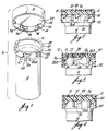
- Fig. 1 is an isometric view of the closure and container showing a portion of the interior of the closure and the container and illustrating the locking elements formed on the closure and the container;
- Fig. 2 is a side view in enlarged scale partially in section and partially broken away from compactness of illustration showing the closure over the mouth of the container prior to moving the closure into a sealing, locking position;
- Fig. 3 is a side view in enlarged scale partially in section and partial broken away for compactness of illustration showing the closure in a fully downward position over the mouth of the container with the stop elements of the closure latches aligned with the through-running channels of the container;
- Fig. 4 is a side view in enlarged scale partially in section and partially broken away for compactness of illustration showing the closure in the locked, sealing position on the container;
- Fig. 5 is a fragmentary, transverse, vertical section, drawn in enlarged scale, of a portion of a container and closure showing one set of locking elements of the present invention in the locked and sealed position and showing by dotted lines typical damage caused by the forced removal of the closure and the repositioning of the latch member after such damage; and
- Fig. 6 is a view corresponding to that of Fig. 5 but showing a set of locking elements designed in accordance with the prior art and showing by dotted lines typical damage caused by the forced removal of the closure.
- Referring to the drawings and particularly to Fig. 1, there is shown a
package 10 comprising aclosure 12 and acontainer 14 having anopen mouth 16. Thepackage 10 is of the type commonly used in packaging pharmaceutical products, although the invention is not so limited and may be utilized for the packaging of any products where it is desired that the closure be locked on the container. Theclosure 12 has atop wall 18 which carries a resilient sealing member of any type well known in the art such as, for example, a resilient cylindrical member adapted to be received in themouth 16 of thecontainer 14 or, as illustrated, anelastomeric liner 20. Theclosure 12 further includes a cylindrical dependingskirt 22 havinglatch members 24 formed on the inner surface thereof, the configuration and purpose of which will be more fully described. The container includesprojections open mouth 12 in spaced apart pairs to define a through-runningchannel 28 between each pair of the projections. - The
closure 12 andcontainer 14 are preferably molded from a moisture-resistant material such as polyethylene or polypropylene and thelatch members 24 andprojections closure 12 to provide what is commonly described as a "single-piece cap" or, as illustrated, may be aseparate liner 20 formed of a resilient compressible material such as foamed polyurethane or neoprene rubber or the like over which may be laid a flexible, fluid impervious outer layer so that the liner is adapted to fit around the rim of thecontainer 14 to form a fluid tight seal therewith when the closure is drawn down over themouth 16 of the container. In addition, the resilient action may be accompanied by inwardly biasing the other surface of thecontainer 14 adjacent themouth 16 to provide a resilient rim which cooperates with a correspondingly biased ring member disposed in theskirt 22 of theclosure 12 adjacent thetop wall 18. When sealed, the resilient rim is received in the ring member of the closure and is compressed inwardly by the ring member to provide the required resiliency to urge theclosure 12 axially upwardly and to provide a fluid tight seal of thecontainer 14. - In accordance with the invention, each
latch member 24 defines aretaining portion 32 and astop element 34 which extends beyond the retaining element. The lower surface of each of theprojections 26 is preferably disposed in an angular plane with respect to the axis of thecontainer 14 to define acamming surface 26a. Eachprojection 27 is preferably axially extended with respect to theprojections 26 and the spacing between each pair of theprojections channel 28 is slightly wider than thestop element 34. - Referring to Figs. 2-4 the
closure 12 is placed over themouth 16 of thecontainer 14 and as is illustrated, each of the pairs ofprojections latch members 24 to freely pass so that theelastomeric liner 20 contacts the rim of the container (Fig. 2). As theclosure 12 is twisted in a clockwise direction, each of thelatch members 24 contacts thecamming surface 26a of acorresponding projection 26 on the counter-clockwise side of each pair to draw the closure axially downwardly over thecontainer mouth 16 and compressing theelastomeric liner 16. Thestop element 34 is brought into alignment with the through-running channel 28 (Fig. 3). Responsive to the upward urging of thecompressed liner 22, the stop element is moved into the through-running channel to lock theclosure 12 on thecontainer 14 and the retainingportion 32 contacts theprojection 26 to hold theclosure 12 in sealed position against the urging of the compressed elastomeric liner 20 (Fig. 4). Theelongated projection 27 prevents further turning of theclosure 12 in a clockwise direction even if sufficient downward force is applied to the closure to prevent thestop element 34 from moving into the through-runningchannel 28. Thin provides a positive indication of the alignment of the atop element with the through-running channel and prevents removal of the closure by continued rotation in the clockwise direction. As mentioned, thechannel 28 is preferably dimensioned to be slightly larger than thestop element 34 so that there is maintained a minimum of play between theclosure 12 and thecontainer 14 to provide a tight lock between the closure and the container. - The
closure 12 is removed by applying sufficient force on the closure to move thestop element 34 out of thechannel 28 while twisting the closure in a counterclockwise direction. This manipulation is normally beyond the capabilities of most young children, thus rendering the package child resistant. - However, as with any child resistant package, there is the possibility that through carelessness or otherwise, the package may be forcibly opened without proper manipulation by application of sufficient force to overcome the shear strength of the locking elements, resulting in the shearing of the locking elements which may render the package inoperable as a child resistant package. Normally with locking elements of the general type described herein, that is, where the design of one of the elements is of the bayonet or hook lug configuration, the bayonet or hook lug will shear in preference to the corresponding element with which it cooperates to provide the locking action. Referring to Fig. 6 wherein like number indicates like parts already described, there is illustrated a portion of a container and a closure which is provided with a resilient member such as the
elastomeric liner 20 which functions in the manner already described. The locking elements comprise a unitarybayonet type lug 40 of prior art design. Thebayonet lug 40 includes afirst portion 41a and a second portion 41b which are spaced apart to define anotch 43 therebetween. Acorresponding lug 45, which is normally disposed on the closure member, is received in anotch 43 to lock the elements and the bed of the notch retains the lug against the urging of theresilient member 20 of the closure. - Forced removal of the closure produces a shearing of the
first portion 41a of the bayonet lug as indicated bydotted line 47. As will be apparent, any shearing away of thefirst portion 41a substantially reduces the locking effect of the bayonet lug 41 and as illustrated, the locking action is essentially eliminated, since there is no surface for thelug 45 to act against to resist counter rotation of the closure. - Referring to Fig. 5, which illustrates locking elements in accordance with the present invention and like numbers designate like parts already described, there is shown by
dotted line 49 that portion ofprojection 26 remaining after shearing due to the forced removal of the closure. As shown, when theclosure 12 is replaced on thecontainer 14, thestop element 34 is permitted to move up further in the through-runningchannel 28 to engage the remaining undamaged portion of theprojection 26 to provide the locking action, even though a substantial portion of the projection has been sheared away. - It should be understood that for purposes of illustration, the shearing action resulting from the forced removal of a closure has been shown as a worst case, but it should be clear that any reduction in the contact surface area between the corresponding locking elements reduces the locking effect of the elements and renders the package easier to open without manipulation and therefore less child resistant. In accordance with the invention, the locking elements are able to be adjusted to compensate for the effects of forced removal of the closure retaining as much as possible the child resistant features of the package, even after misuse.
- Although not preferred, it will be apparent that the placement of the locking elements may be reversed and that the
latch member 24 may be placed on thecontainer 14 and theprojections 25 and 27 placed on theclosure 12.
Claims (7)
Priority Applications (1)
| Application Number | Priority Date | Filing Date | Title |
|---|---|---|---|
| AT87900771T ATE75200T1 (en) | 1986-01-03 | 1986-12-31 | CHILD-RESISTANT PACKAGING. |
Applications Claiming Priority (2)
| Application Number | Priority Date | Filing Date | Title |
|---|---|---|---|
| US816009 | 1986-01-03 | ||
| US06/816,009 US4627547A (en) | 1986-01-03 | 1986-01-03 | Child resistant package |
Publications (3)
| Publication Number | Publication Date |
|---|---|
| EP0253854A1 EP0253854A1 (en) | 1988-01-27 |
| EP0253854A4 EP0253854A4 (en) | 1989-07-11 |
| EP0253854B1 true EP0253854B1 (en) | 1992-04-22 |
Family
ID=25219431
Family Applications (1)
| Application Number | Title | Priority Date | Filing Date |
|---|---|---|---|
| EP87900771A Expired EP0253854B1 (en) | 1986-01-03 | 1986-12-31 | Child resistant package |
Country Status (9)
| Country | Link |
|---|---|
| US (1) | US4627547A (en) |
| EP (1) | EP0253854B1 (en) |
| JP (1) | JPH0737270B2 (en) |
| AT (1) | ATE75200T1 (en) |
| AU (1) | AU591548B2 (en) |
| CA (1) | CA1284629C (en) |
| DE (1) | DE3685027D1 (en) |
| DK (1) | DK451987D0 (en) |
| WO (1) | WO1987004135A1 (en) |
Families Citing this family (23)
| Publication number | Priority date | Publication date | Assignee | Title |
|---|---|---|---|---|
| US4739890A (en) * | 1987-06-15 | 1988-04-26 | Cooke Carl W | Closure for container |
| US4834251A (en) * | 1988-01-21 | 1989-05-30 | Yu Hon T | Child-proof measuring cup |
| US5188399A (en) * | 1990-12-31 | 1993-02-23 | Spirex Corporation | Pipe coupling device and method |
| WO1992019136A1 (en) * | 1991-04-24 | 1992-11-12 | Shamis Neal B | Closure system for covered receptacles and the like |
| US5806724A (en) * | 1996-06-04 | 1998-09-15 | Contico International, Inc. | Dispenser with improved bottle connection and method of making same |
| FR2801569B1 (en) * | 1999-11-29 | 2002-04-26 | Valois Sa | SAFETY CAP |
| WO2004065243A1 (en) * | 2003-01-22 | 2004-08-05 | MØLLER, Claus, Schmidt | A locking arrangement for a container with a cap |
| US20050263477A1 (en) * | 2003-10-13 | 2005-12-01 | Konefal Robert S | Closure and container package with child-resistant and non-child-resistant modes of operation |
| US7527159B2 (en) | 2004-03-11 | 2009-05-05 | Rexam Closure Systems Inc. | Threaded child-resistant package having linerless closure |
| US7819264B2 (en) * | 2003-12-03 | 2010-10-26 | Rexam Closure Systems Inc. | Child-resistant closure, container and package |
| US7185776B1 (en) | 2004-02-16 | 2007-03-06 | Owens-Illinois Prescription Products Inc. | Closure and container package |
| US7703617B1 (en) | 2004-11-19 | 2010-04-27 | Rexam Closures And Containers, Inc. | Bayonet closure container combination with angled bayonet lugs |
| US20060186081A1 (en) * | 2005-02-21 | 2006-08-24 | Penn-Wheeling Closure, Llc | Bottle cap and method therefor |
| US20060213912A1 (en) * | 2005-03-28 | 2006-09-28 | Amanda Zaytoun | Child-proof drink bottle |
| US20060273060A1 (en) * | 2005-06-06 | 2006-12-07 | Mark Fricke | Reversible vial closure |
| US20080169288A1 (en) * | 2007-01-12 | 2008-07-17 | Michael Dawn | Receptacle having a securable lid |
| US20110056948A1 (en) * | 2009-09-04 | 2011-03-10 | Pacific Management Holding, Llc | Pharmaceutical Container Having Non-Child-Resistant Closure |
| DE102010000743A1 (en) * | 2010-01-08 | 2011-07-14 | Hamilton Bonaduz Ag | Sample container i.e. culture container, for holding e.g. biological cell culture to breed cell in research laboratory, has locking parts brought from locking position into other locking position, in which cover part is latched at base part |
| US20130309147A1 (en) * | 2012-05-16 | 2013-11-21 | Gene Era Biotech Co. Ltd. | Sample tube with improved seal |
| CN108013509B (en) * | 2016-10-31 | 2021-07-02 | 卓尔悦欧洲控股有限公司 | Atomizer and electronic cigarette thereof |
| US10927973B2 (en) * | 2018-12-12 | 2021-02-23 | Bendix Commercial Vehicle Systems Llc | Pneumatic valve/pressure vessel subcomponent with bayonet retention feature |
| US10927968B2 (en) * | 2018-12-12 | 2021-02-23 | Bendix Commercial Vehicle Systems Llc | Pneumatic valve/pressure vessel plastic metal composite cover with bayonet retention feature |
| USD927979S1 (en) * | 2019-07-29 | 2021-08-17 | MEG Group | Child resistant tamper evident jar |
Family Cites Families (4)
| Publication number | Priority date | Publication date | Assignee | Title |
|---|---|---|---|---|
| US3880313A (en) * | 1968-03-04 | 1975-04-29 | Edward G Akers | Safety cap and container |
| US4434903A (en) * | 1982-11-22 | 1984-03-06 | Cooke Carl W | Safety closure and container |
| EP0147951B1 (en) * | 1983-12-01 | 1988-09-07 | Johnsen & Jorgensen (Plastics) Limited | A child resistant and tamper-resistant container and closure assembly |
| US4526281A (en) * | 1984-08-09 | 1985-07-02 | Kerr Glass Manufacturing Corporation | Moisture tight closure and container |
-
1986
- 1986-01-03 US US06/816,009 patent/US4627547A/en not_active Expired - Lifetime
- 1986-12-31 DE DE8787900771T patent/DE3685027D1/en not_active Expired - Fee Related
- 1986-12-31 AT AT87900771T patent/ATE75200T1/en not_active IP Right Cessation
- 1986-12-31 AU AU68980/87A patent/AU591548B2/en not_active Ceased
- 1986-12-31 EP EP87900771A patent/EP0253854B1/en not_active Expired
- 1986-12-31 WO PCT/US1986/002834 patent/WO1987004135A1/en active IP Right Grant
- 1986-12-31 CA CA000526573A patent/CA1284629C/en not_active Expired - Lifetime
- 1986-12-31 JP JP62500715A patent/JPH0737270B2/en not_active Expired - Lifetime
-
1987
- 1987-08-28 DK DK451987A patent/DK451987D0/en not_active Application Discontinuation
Also Published As
| Publication number | Publication date |
|---|---|
| JPH0737270B2 (en) | 1995-04-26 |
| EP0253854A4 (en) | 1989-07-11 |
| DE3685027D1 (en) | 1992-05-27 |
| JPS63502653A (en) | 1988-10-06 |
| US4627547A (en) | 1986-12-09 |
| AU591548B2 (en) | 1989-12-07 |
| DK451987A (en) | 1987-08-28 |
| EP0253854A1 (en) | 1988-01-27 |
| AU6898087A (en) | 1987-07-28 |
| CA1284629C (en) | 1991-06-04 |
| WO1987004135A1 (en) | 1987-07-16 |
| ATE75200T1 (en) | 1992-05-15 |
| DK451987D0 (en) | 1987-08-28 |
Similar Documents
| Publication | Publication Date | Title |
|---|---|---|
| EP0253854B1 (en) | Child resistant package | |
| EP0116071B1 (en) | Container closure | |
| US4444327A (en) | Tight vial assembly with one-piece cap | |
| US4434903A (en) | Safety closure and container | |
| US5449078A (en) | Combination of a container and a safety cap therefor | |
| US4059198A (en) | Vapor-seal safety cap and container | |
| US5462182A (en) | Screws-on child resistant consumer-friendly closure | |
| US4620640A (en) | Lined child-resistant closure for widemouth liquid container | |
| CA1113887A (en) | Plastic cap and bottle neck | |
| US3795337A (en) | Safety cap | |
| US3888376A (en) | Safety closure cap for containers | |
| US3830393A (en) | Snap-on safety closure for flexible containers | |
| GB2096981A (en) | Moisture tight closure and container system | |
| US3777936A (en) | Safety dispensing closure | |
| GB2155912A (en) | Tamper resistant and tamper evident closures | |
| GB2148860A (en) | Child resistant safety cap | |
| US20060273060A1 (en) | Reversible vial closure | |
| US4664273A (en) | Child-resistant container with resistance indicating means | |
| US7469794B2 (en) | Child resistant container-closure assembly | |
| GB2101106A (en) | Child resistant closure and container assembly | |
| US5826738A (en) | Child-restraint combination of a container and a one-piece closure | |
| US3753510A (en) | Liquid proof safety package | |
| US4002259A (en) | Safety closure | |
| US6112920A (en) | Child-proof, senior-friendly pill bottle closure | |
| JP4881670B2 (en) | Container with cap |
Legal Events
| Date | Code | Title | Description |
|---|---|---|---|
| PUAI | Public reference made under article 153(3) epc to a published international application that has entered the european phase |
Free format text: ORIGINAL CODE: 0009012 |
|
| 17P | Request for examination filed |
Effective date: 19870814 |
|
| AK | Designated contracting states |
Kind code of ref document: A1 Designated state(s): AT BE CH DE FR GB IT LI LU NL SE |
|
| R17P | Request for examination filed (corrected) |
Effective date: 19880205 |
|
| A4 | Supplementary search report drawn up and despatched |
Effective date: 19890711 |
|
| 17Q | First examination report despatched |
Effective date: 19910213 |
|
| GRAA | (expected) grant |
Free format text: ORIGINAL CODE: 0009210 |
|
| ITF | It: translation for a ep patent filed |
Owner name: GUZZI E RAVIZZA S.R.L. |
|
| AK | Designated contracting states |
Kind code of ref document: B1 Designated state(s): AT BE CH DE FR GB IT LI LU NL SE |
|
| REF | Corresponds to: |
Ref document number: 75200 Country of ref document: AT Date of ref document: 19920515 Kind code of ref document: T |
|
| REF | Corresponds to: |
Ref document number: 3685027 Country of ref document: DE Date of ref document: 19920527 |
|
| ET | Fr: translation filed | ||
| PLBE | No opposition filed within time limit |
Free format text: ORIGINAL CODE: 0009261 |
|
| STAA | Information on the status of an ep patent application or granted ep patent |
Free format text: STATUS: NO OPPOSITION FILED WITHIN TIME LIMIT |
|
| 26N | No opposition filed | ||
| EPTA | Lu: last paid annual fee | ||
| EAL | Se: european patent in force in sweden |
Ref document number: 87900771.4 |
|
| PGFP | Annual fee paid to national office [announced via postgrant information from national office to epo] |
Ref country code: SE Payment date: 19981207 Year of fee payment: 13 |
|
| PGFP | Annual fee paid to national office [announced via postgrant information from national office to epo] |
Ref country code: FR Payment date: 19981209 Year of fee payment: 13 |
|
| PGFP | Annual fee paid to national office [announced via postgrant information from national office to epo] |
Ref country code: AT Payment date: 19981214 Year of fee payment: 13 |
|
| PGFP | Annual fee paid to national office [announced via postgrant information from national office to epo] |
Ref country code: LU Payment date: 19981221 Year of fee payment: 13 |
|
| PGFP | Annual fee paid to national office [announced via postgrant information from national office to epo] |
Ref country code: NL Payment date: 19981229 Year of fee payment: 13 |
|
| PGFP | Annual fee paid to national office [announced via postgrant information from national office to epo] |
Ref country code: GB Payment date: 19981231 Year of fee payment: 13 |
|
| PGFP | Annual fee paid to national office [announced via postgrant information from national office to epo] |
Ref country code: DE Payment date: 19990108 Year of fee payment: 13 |
|
| PGFP | Annual fee paid to national office [announced via postgrant information from national office to epo] |
Ref country code: CH Payment date: 19990115 Year of fee payment: 13 |
|
| PGFP | Annual fee paid to national office [announced via postgrant information from national office to epo] |
Ref country code: BE Payment date: 19990215 Year of fee payment: 13 |
|
| PG25 | Lapsed in a contracting state [announced via postgrant information from national office to epo] |
Ref country code: LU Free format text: LAPSE BECAUSE OF NON-PAYMENT OF DUE FEES Effective date: 19991231 Ref country code: LI Free format text: LAPSE BECAUSE OF NON-PAYMENT OF DUE FEES Effective date: 19991231 Ref country code: GB Free format text: LAPSE BECAUSE OF NON-PAYMENT OF DUE FEES Effective date: 19991231 Ref country code: CH Free format text: LAPSE BECAUSE OF NON-PAYMENT OF DUE FEES Effective date: 19991231 Ref country code: BE Free format text: LAPSE BECAUSE OF NON-PAYMENT OF DUE FEES Effective date: 19991231 Ref country code: AT Free format text: LAPSE BECAUSE OF NON-PAYMENT OF DUE FEES Effective date: 19991231 |
|
| PG25 | Lapsed in a contracting state [announced via postgrant information from national office to epo] |
Ref country code: SE Free format text: LAPSE BECAUSE OF NON-PAYMENT OF DUE FEES Effective date: 20000101 |
|
| BERE | Be: lapsed |
Owner name: INVENTIVE PACKAGING CORP. Effective date: 19991231 |
|
| PG25 | Lapsed in a contracting state [announced via postgrant information from national office to epo] |
Ref country code: NL Free format text: LAPSE BECAUSE OF NON-PAYMENT OF DUE FEES Effective date: 20000701 |
|
| GBPC | Gb: european patent ceased through non-payment of renewal fee |
Effective date: 19991231 |
|
| PG25 | Lapsed in a contracting state [announced via postgrant information from national office to epo] |
Ref country code: FR Free format text: LAPSE BECAUSE OF NON-PAYMENT OF DUE FEES Effective date: 20000831 |
|
| NLV4 | Nl: lapsed or anulled due to non-payment of the annual fee |
Effective date: 20000701 |
|
| EUG | Se: european patent has lapsed |
Ref document number: 87900771.4 |
|
| PG25 | Lapsed in a contracting state [announced via postgrant information from national office to epo] |
Ref country code: DE Free format text: LAPSE BECAUSE OF NON-PAYMENT OF DUE FEES Effective date: 20001003 |
|
| REG | Reference to a national code |
Ref country code: FR Ref legal event code: ST |
|
| PG25 | Lapsed in a contracting state [announced via postgrant information from national office to epo] |
Ref country code: IT Free format text: LAPSE BECAUSE OF NON-PAYMENT OF DUE FEES;WARNING: LAPSES OF ITALIAN PATENTS WITH EFFECTIVE DATE BEFORE 2007 MAY HAVE OCCURRED AT ANY TIME BEFORE 2007. THE CORRECT EFFECTIVE DATE MAY BE DIFFERENT FROM THE ONE RECORDED. Effective date: 20051231 |