US4481014A - Arrangement for producing gaseous products - Google Patents
Arrangement for producing gaseous products Download PDFInfo
- Publication number
- US4481014A US4481014A US06/350,337 US35033782A US4481014A US 4481014 A US4481014 A US 4481014A US 35033782 A US35033782 A US 35033782A US 4481014 A US4481014 A US 4481014A
- Authority
- US
- United States
- Prior art keywords
- reactor
- gaseous products
- arrangement
- annular chamber
- flow
- Prior art date
- Legal status (The legal status is an assumption and is not a legal conclusion. Google has not performed a legal analysis and makes no representation as to the accuracy of the status listed.)
- Expired - Fee Related
Links
Images


Classifications
-
- C—CHEMISTRY; METALLURGY
- C10—PETROLEUM, GAS OR COKE INDUSTRIES; TECHNICAL GASES CONTAINING CARBON MONOXIDE; FUELS; LUBRICANTS; PEAT
- C10J—PRODUCTION OF PRODUCER GAS, WATER-GAS, SYNTHESIS GAS FROM SOLID CARBONACEOUS MATERIAL, OR MIXTURES CONTAINING THESE GASES; CARBURETTING AIR OR OTHER GASES
- C10J3/00—Production of combustible gases containing carbon monoxide from solid carbonaceous fuels
- C10J3/72—Other features
- C10J3/86—Other features combined with waste-heat boilers
-
- C—CHEMISTRY; METALLURGY
- C10—PETROLEUM, GAS OR COKE INDUSTRIES; TECHNICAL GASES CONTAINING CARBON MONOXIDE; FUELS; LUBRICANTS; PEAT
- C10J—PRODUCTION OF PRODUCER GAS, WATER-GAS, SYNTHESIS GAS FROM SOLID CARBONACEOUS MATERIAL, OR MIXTURES CONTAINING THESE GASES; CARBURETTING AIR OR OTHER GASES
- C10J3/00—Production of combustible gases containing carbon monoxide from solid carbonaceous fuels
- C10J3/46—Gasification of granular or pulverulent flues in suspension
- C10J3/48—Apparatus; Plants
- C10J3/485—Entrained flow gasifiers
-
- C—CHEMISTRY; METALLURGY
- C10—PETROLEUM, GAS OR COKE INDUSTRIES; TECHNICAL GASES CONTAINING CARBON MONOXIDE; FUELS; LUBRICANTS; PEAT
- C10J—PRODUCTION OF PRODUCER GAS, WATER-GAS, SYNTHESIS GAS FROM SOLID CARBONACEOUS MATERIAL, OR MIXTURES CONTAINING THESE GASES; CARBURETTING AIR OR OTHER GASES
- C10J3/00—Production of combustible gases containing carbon monoxide from solid carbonaceous fuels
- C10J3/46—Gasification of granular or pulverulent flues in suspension
- C10J3/48—Apparatus; Plants
- C10J3/52—Ash-removing devices
- C10J3/526—Ash-removing devices for entrained flow gasifiers
-
- C—CHEMISTRY; METALLURGY
- C10—PETROLEUM, GAS OR COKE INDUSTRIES; TECHNICAL GASES CONTAINING CARBON MONOXIDE; FUELS; LUBRICANTS; PEAT
- C10J—PRODUCTION OF PRODUCER GAS, WATER-GAS, SYNTHESIS GAS FROM SOLID CARBONACEOUS MATERIAL, OR MIXTURES CONTAINING THESE GASES; CARBURETTING AIR OR OTHER GASES
- C10J3/00—Production of combustible gases containing carbon monoxide from solid carbonaceous fuels
- C10J3/72—Other features
- C10J3/74—Construction of shells or jackets
-
- C—CHEMISTRY; METALLURGY
- C10—PETROLEUM, GAS OR COKE INDUSTRIES; TECHNICAL GASES CONTAINING CARBON MONOXIDE; FUELS; LUBRICANTS; PEAT
- C10J—PRODUCTION OF PRODUCER GAS, WATER-GAS, SYNTHESIS GAS FROM SOLID CARBONACEOUS MATERIAL, OR MIXTURES CONTAINING THESE GASES; CARBURETTING AIR OR OTHER GASES
- C10J3/00—Production of combustible gases containing carbon monoxide from solid carbonaceous fuels
- C10J3/72—Other features
- C10J3/78—High-pressure apparatus
-
- C—CHEMISTRY; METALLURGY
- C10—PETROLEUM, GAS OR COKE INDUSTRIES; TECHNICAL GASES CONTAINING CARBON MONOXIDE; FUELS; LUBRICANTS; PEAT
- C10J—PRODUCTION OF PRODUCER GAS, WATER-GAS, SYNTHESIS GAS FROM SOLID CARBONACEOUS MATERIAL, OR MIXTURES CONTAINING THESE GASES; CARBURETTING AIR OR OTHER GASES
- C10J3/00—Production of combustible gases containing carbon monoxide from solid carbonaceous fuels
- C10J3/72—Other features
- C10J3/82—Gas withdrawal means
- C10J3/84—Gas withdrawal means with means for removing dust or tar from the gas
-
- C—CHEMISTRY; METALLURGY
- C10—PETROLEUM, GAS OR COKE INDUSTRIES; TECHNICAL GASES CONTAINING CARBON MONOXIDE; FUELS; LUBRICANTS; PEAT
- C10J—PRODUCTION OF PRODUCER GAS, WATER-GAS, SYNTHESIS GAS FROM SOLID CARBONACEOUS MATERIAL, OR MIXTURES CONTAINING THESE GASES; CARBURETTING AIR OR OTHER GASES
- C10J2300/00—Details of gasification processes
- C10J2300/09—Details of the feed, e.g. feeding of spent catalyst, inert gas or halogens
- C10J2300/0953—Gasifying agents
- C10J2300/0956—Air or oxygen enriched air
-
- Y—GENERAL TAGGING OF NEW TECHNOLOGICAL DEVELOPMENTS; GENERAL TAGGING OF CROSS-SECTIONAL TECHNOLOGIES SPANNING OVER SEVERAL SECTIONS OF THE IPC; TECHNICAL SUBJECTS COVERED BY FORMER USPC CROSS-REFERENCE ART COLLECTIONS [XRACs] AND DIGESTS
- Y10—TECHNICAL SUBJECTS COVERED BY FORMER USPC
- Y10S—TECHNICAL SUBJECTS COVERED BY FORMER USPC CROSS-REFERENCE ART COLLECTIONS [XRACs] AND DIGESTS
- Y10S48/00—Gas: heating and illuminating
- Y10S48/02—Slagging producer
Definitions
- the present invention relates to an arrangement for producing gaseous products from solid and liquid, ash-containing fuels and mixtures thereof in an air stream in a reactor; the fuels are introduced into the reactor parallel to the axis thereof and the solid and liquid ash constituents are extensively separated from the gaseous products thereof in a slag bath before further cooling-off.
- the production of gaseous products from solid and gaseous, ash-containing fuels and mixtures thereof in an air stream in a reactor is known.
- the produced gaseous products are loaded with solid and liquid ash constituents, which require measures for separating them off.
- Measures for separating the solid and liquid ash constituents from the produced gaseous products are provided externally of the reactor according to the known state of the art. Special apparatus is utilized. Separating the solid and liquid constituents with external measures requires considerable design and construction expense, as well as extra space.
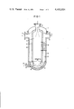
- FIG. 1 shows one embodiment of an arrangement according to the present invention, and in particular is a longitudinal section with heat exchanger surfaces arranged in an annular chamber on the right side, and showing the annular chamber without the heat exchanger surfaces on the left side;
- FIG. 2 shows an embodiment of the arrangement according to the present invention with two annular chambers arranged concentrically around the reactor;
- FIG. 3 shows the arrangement according to FIG. 1 with reverse flow of the process media.
- the arrangement of the present invention is characterized primarily in that the gaseous products, which are loaded with solid and liquid ash constituents, are reversed by 180° after leaving the reactor, and subsequently flow into one or more consecutively or parallel connected annular chambers which concentrically surround the reactor and are provided with heat exchanger heating surfaces; the gaseous products are cooled in these annular chambers.
- the introduction into the reactor of the fuels which are to be reacted can occur in different ways.
- the fuels can be introduced into the reactor in an axially parallel flow from top to bottom through the reactor, and can, as a product flow, be reversed by 180° directly above the slag mass which is arranged below the reactor.
- the fuels which are to be reacted and which are introduced into the reactor can also flow axially parallel from below to the top through the reactor, with the product flow, after extensive separating off of the solid and liquid ash constituents within the reactor in a slag bath arranged in the bottom of the reactor, being reversed in the upper region of the reactor by 180°.
- the product flow in a further arrangement according to the present invention can be cooled off in the region of the 180° reversal by the addition of a coolant flow.
- the one or more annular chambers may be provided internally and externally with heating surfaces, with the inner heating surface simultaneously serving as the support structure for the reactor brick lining, and receiving or absorbing the forces arising as a result of the pressure difference between the reactor and the annular chambers.
- heat exchanger heating surfaces in an annular chamber be constructed as radiation heating surfaces and/or as contact heating surfaces.
- the present invention further also allows for the provision of inserts wich influence the material flow in the discharge-flow region of the reactor as well as in the inlet-flow region of the annular chamber. It is also within the scope of the present invention to line the heating surfaces with thermally insulating layers in the lower region of the annular chamber.
- the manner of operation of the arrangement in accordance with the present invention can also occur loaded.
- the outer heating surfaces of the outermost annular chamber are surrounded by a pressure tank.
- the advantages which are attained with the present invention consist in that as a result of the 180° reversal of the produced gaseous product, which is loaded with solid and liquid ash constituents, which reversal can occur one or more times, the solid and liquid ash constituents are separated off to a sufficient extent, and the contamination or fouling of the heating surfaces is reduced to a minimum during the subsequent cooling of the produced gas. Also decisively advantageous is the special arrangement of the heat exchanger surfaces relative to the reactor, which surfaces are located concentrical to the reactor and accordingly permit a compact construction with optimization of the product gas treatment.
- FIG. 1 shows the unit or arrangement 1 in which solid and liquid, ash-containing fuels and mixtures thereof are introduced parallel to the axis of the reactor via the inlet location 2 to the uppermost part of the reactor 3; the fuel is reacted, especially gasified or vaporized.
- the gaseous products leaving the reactor 3 in a downward flow are reversed in their flow direction by 180°, directly above the slag bath 4 located below the reactor 3, at the location 5 of the inner heating surface 6 which surrounds the reactor 3; from there, the products pass into the annular chamber formed between the outermost heating surface 8 and the inner heating surface 6.
- the gaseous products leave the annular chamber of the arrangement 1 uncooled, via the outlet connection 11.
- a heat exchanger 9 embodied as a radiation- and/or as a contact heating surface, for cooling the gas in the annular chamber formed by the outer and inner heating surfaces 6 and 8.
- the solid and liquid ash constituents precipitated or separated-off in the region of the reversal location 5 are carried out via the slag bath 4 and the discharge outlet 10 of the arrangement 1.
- FIG. 2 shows the arrangement 1 in a further embodiment, with two annular chambers surrounding the reactor 3 and being formed by the wall heating surfaces 6, 7 and 8; also provided is a further 180° reversal location 12 at the upper edge of the central wall heating surface 7.
- the reactor of the arrangement 1 has flow therethrough in an upward stream.
- the gaseous products leave the reactor at its highest location, where they are inventively reversed by 180° at the location 5 of the wall heating surface 6.
- the products are conveyed into the annular chamber formed by the wall heating surfaces 6 and 8, from where they leave the arrangement 1 via the outlet connection 11.
- the embodiment of the arrangement according to the present invention as illustrated in FIG. 3 can be modified with respect to the annular chamber which surrounds the reactor 3 in a manner analogous to that illustrated in FIG. 2.
Landscapes
- Chemical & Material Sciences (AREA)
- Engineering & Computer Science (AREA)
- Combustion & Propulsion (AREA)
- Oil, Petroleum & Natural Gas (AREA)
- Organic Chemistry (AREA)
- Physical Or Chemical Processes And Apparatus (AREA)
- Processing Of Solid Wastes (AREA)
Applications Claiming Priority (2)
| Application Number | Priority Date | Filing Date | Title |
|---|---|---|---|
| DE3107156 | 1981-02-26 | ||
| DE19813107156 DE3107156A1 (de) | 1981-02-26 | 1981-02-26 | Anlage zur erzeugung von gasfoermigen produkten |
Publications (1)
| Publication Number | Publication Date |
|---|---|
| US4481014A true US4481014A (en) | 1984-11-06 |
Family
ID=6125775
Family Applications (1)
| Application Number | Title | Priority Date | Filing Date |
|---|---|---|---|
| US06/350,337 Expired - Fee Related US4481014A (en) | 1981-02-26 | 1982-02-19 | Arrangement for producing gaseous products |
Country Status (7)
| Country | Link |
|---|---|
| US (1) | US4481014A (OSRAM) |
| JP (1) | JPS57153087A (OSRAM) |
| AU (1) | AU546518B2 (OSRAM) |
| DE (1) | DE3107156A1 (OSRAM) |
| FR (1) | FR2500470B1 (OSRAM) |
| GB (1) | GB2094828B (OSRAM) |
| ZA (1) | ZA821040B (OSRAM) |
Cited By (12)
| Publication number | Priority date | Publication date | Assignee | Title |
|---|---|---|---|---|
| US4707163A (en) * | 1984-10-29 | 1987-11-17 | Brennstoffinstitut Freiberg | Gasification of coal dust |
| US4929254A (en) * | 1989-07-13 | 1990-05-29 | Set Technology B.V. | Down-draft fixed bed gasifier system |
| US4945978A (en) * | 1987-10-09 | 1990-08-07 | Schmidt'sche Heissdampf Gmbh | Heat exchanger system |
| US5803937A (en) * | 1993-01-14 | 1998-09-08 | L. & C. Steinmuller Gmbh | Method of cooling a dust-laden raw gas from the gasification of a solid carbon-containing fuel |
| US6389996B1 (en) * | 2001-07-06 | 2002-05-21 | Sung-Chuan Mai | Incinerator |
| US20070186473A1 (en) * | 2006-02-16 | 2007-08-16 | General Electric Company | Methods and systems for advanced gasifier solids removal |
| US20080011247A1 (en) * | 2005-07-27 | 2008-01-17 | Alexander Kiplin C | Steam generator to contain and cool synthesis gas |
| CN101135432A (zh) * | 2006-09-01 | 2008-03-05 | 巴布考克及威尔考克斯公司 | 用于容纳和冷却合成气体的蒸汽发生器 |
| US20080166278A1 (en) * | 2007-01-10 | 2008-07-10 | George Albert Goller | Methods and apparatus for cooling syngas in a gasifier |
| US20110162381A1 (en) * | 2010-01-05 | 2011-07-07 | Thacker Pradeep S | System and method for cooling syngas produced from a gasifier |
| US9109171B2 (en) | 2013-11-15 | 2015-08-18 | General Electric Company | System and method for gasification and cooling syngas |
| US20150252273A1 (en) * | 2012-09-28 | 2015-09-10 | Cassandra Oil Technology Ab | Reactor, method of increasing the efficiency in a reactor and use of the reactor |
Families Citing this family (8)
| Publication number | Priority date | Publication date | Assignee | Title |
|---|---|---|---|---|
| FR2530796A1 (fr) * | 1982-07-21 | 1984-01-27 | Creusot Loire | Dispositif de conversion et de recuperation thermique |
| DD261280A3 (de) * | 1987-05-12 | 1988-10-26 | Freiberg Brennstoffinst | Apparat zur vergasung von kohlenstaub |
| GB8828339D0 (en) * | 1988-12-05 | 1989-01-05 | Shell Int Research | Constant volume tubular reactor |
| DE3844347A1 (de) * | 1988-12-30 | 1990-07-05 | Krupp Koppers Gmbh | Verfahren und strahlungskuehler zur strahlungskuehlung eines aus dem vergasungsreaktor austretenden produktgasmengenstromes |
| DK164245C (da) * | 1990-01-05 | 1992-10-26 | Burmeister & Wains Energi | Gaskoeler for varmeovergang ved straaling |
| DE4300776C2 (de) * | 1993-01-14 | 1995-07-06 | Steinmueller Gmbh L & C | Verfahren zum Kühlen eines staubbeladenen Rohgases aus der Vergasung eines festen kohlenstoffhaltigen Brennstoffes in einem Reaktor unter Druck und Anlage zur Durchführung des Verfahrens |
| DK0616023T3 (da) * | 1993-03-16 | 1996-04-09 | Krupp Koppers Gmbh | Forgasningsapparat til trykforgasning af findelt brændstof |
| ES2078078T3 (es) * | 1993-03-16 | 1995-12-01 | Krupp Koppers Gmbh | Procedimiento para la gasificacion bajo presion de combustibles finamente divididos. |
Citations (3)
| Publication number | Priority date | Publication date | Assignee | Title |
|---|---|---|---|---|
| US1719874A (en) * | 1923-08-18 | 1929-07-09 | William B Chapman | Apparatus for burning finely-divided coal |
| US4314826A (en) * | 1979-08-18 | 1982-02-09 | M.A.N. Maschinenfabrik Augsburg-Nurnberg Aktiengesellschaft | Coal gasification apparatus |
| US4328007A (en) * | 1979-08-21 | 1982-05-04 | Deutsche Babcock Aktiengesellschaft | Apparatus for gasification of fine-grain coal |
Family Cites Families (5)
| Publication number | Priority date | Publication date | Assignee | Title |
|---|---|---|---|---|
| FR1070615A (fr) * | 1951-12-12 | 1954-08-03 | Babcock & Wilcox France | Générateur de vapeur combiné à un appareil de production de gaz de synthèse |
| DE1596323A1 (de) * | 1967-06-06 | 1970-04-02 | Walther & Cie Ag | Synthesegaserzeuger mit Gaskuehler,die in einem Druckzylinder angeordnet sind |
| DE2705558B2 (de) * | 1977-02-10 | 1980-10-23 | Ruhrchemie Ag, 4200 Oberhausen | Verfahren und Vorrichtung zum Vergasen von festen Brennstoffen, insbesondere Kohle durch partielle Oxidation |
| US4213935A (en) * | 1978-06-19 | 1980-07-22 | John Zink Company | Apparatus for use in conjunction with boiler flue gases for generating inert blanketing gases |
| DE2940257C2 (de) * | 1979-10-04 | 1984-11-08 | Ruhrchemie Ag, 4200 Oberhausen | Strahlungskessel für die Abkühlung eines feste und schmelzflüssige Partikel enthaltenden Gasstromes |
-
1981
- 1981-02-26 DE DE19813107156 patent/DE3107156A1/de active Granted
-
1982
- 1982-02-16 FR FR8202501A patent/FR2500470B1/fr not_active Expired
- 1982-02-17 ZA ZA821040A patent/ZA821040B/xx unknown
- 1982-02-18 JP JP57023693A patent/JPS57153087A/ja active Pending
- 1982-02-19 US US06/350,337 patent/US4481014A/en not_active Expired - Fee Related
- 1982-02-22 GB GB8205158A patent/GB2094828B/en not_active Expired
- 1982-02-25 AU AU80776/82A patent/AU546518B2/en not_active Ceased
Patent Citations (3)
| Publication number | Priority date | Publication date | Assignee | Title |
|---|---|---|---|---|
| US1719874A (en) * | 1923-08-18 | 1929-07-09 | William B Chapman | Apparatus for burning finely-divided coal |
| US4314826A (en) * | 1979-08-18 | 1982-02-09 | M.A.N. Maschinenfabrik Augsburg-Nurnberg Aktiengesellschaft | Coal gasification apparatus |
| US4328007A (en) * | 1979-08-21 | 1982-05-04 | Deutsche Babcock Aktiengesellschaft | Apparatus for gasification of fine-grain coal |
Cited By (18)
| Publication number | Priority date | Publication date | Assignee | Title |
|---|---|---|---|---|
| US4707163A (en) * | 1984-10-29 | 1987-11-17 | Brennstoffinstitut Freiberg | Gasification of coal dust |
| US4945978A (en) * | 1987-10-09 | 1990-08-07 | Schmidt'sche Heissdampf Gmbh | Heat exchanger system |
| US4929254A (en) * | 1989-07-13 | 1990-05-29 | Set Technology B.V. | Down-draft fixed bed gasifier system |
| US5803937A (en) * | 1993-01-14 | 1998-09-08 | L. & C. Steinmuller Gmbh | Method of cooling a dust-laden raw gas from the gasification of a solid carbon-containing fuel |
| US6389996B1 (en) * | 2001-07-06 | 2002-05-21 | Sung-Chuan Mai | Incinerator |
| US20080011247A1 (en) * | 2005-07-27 | 2008-01-17 | Alexander Kiplin C | Steam generator to contain and cool synthesis gas |
| US7931710B2 (en) * | 2005-07-27 | 2011-04-26 | Babcock & Wilcox Power Generation Group, Inc. | Steam generator to contain and cool synthesis gas |
| US20070186473A1 (en) * | 2006-02-16 | 2007-08-16 | General Electric Company | Methods and systems for advanced gasifier solids removal |
| US7744663B2 (en) * | 2006-02-16 | 2010-06-29 | General Electric Company | Methods and systems for advanced gasifier solids removal |
| CN101135432B (zh) * | 2006-09-01 | 2013-04-24 | 巴布考克及威尔考克斯公司 | 用于容纳和冷却合成气体的蒸汽发生器 |
| CN101135432A (zh) * | 2006-09-01 | 2008-03-05 | 巴布考克及威尔考克斯公司 | 用于容纳和冷却合成气体的蒸汽发生器 |
| US20080166278A1 (en) * | 2007-01-10 | 2008-07-10 | George Albert Goller | Methods and apparatus for cooling syngas in a gasifier |
| US8163047B2 (en) * | 2007-01-10 | 2012-04-24 | General Electric Company | Methods and apparatus for cooling syngas in a gasifier |
| US20110162381A1 (en) * | 2010-01-05 | 2011-07-07 | Thacker Pradeep S | System and method for cooling syngas produced from a gasifier |
| US8769964B2 (en) * | 2010-01-05 | 2014-07-08 | General Electric Company | System and method for cooling syngas produced from a gasifier |
| US20150252273A1 (en) * | 2012-09-28 | 2015-09-10 | Cassandra Oil Technology Ab | Reactor, method of increasing the efficiency in a reactor and use of the reactor |
| US9677017B2 (en) * | 2012-09-28 | 2017-06-13 | Cassandra Oil Technology Ab | Reactor, method of increasing the efficiency in a reactor and use of the reactor |
| US9109171B2 (en) | 2013-11-15 | 2015-08-18 | General Electric Company | System and method for gasification and cooling syngas |
Also Published As
| Publication number | Publication date |
|---|---|
| DE3107156A1 (de) | 1982-09-16 |
| DE3107156C2 (OSRAM) | 1988-02-04 |
| AU546518B2 (en) | 1985-09-05 |
| ZA821040B (en) | 1982-12-29 |
| JPS57153087A (en) | 1982-09-21 |
| FR2500470B1 (fr) | 1985-10-11 |
| AU8077682A (en) | 1982-09-02 |
| GB2094828A (en) | 1982-09-22 |
| GB2094828B (en) | 1984-11-28 |
| FR2500470A1 (fr) | 1982-08-27 |
Similar Documents
| Publication | Publication Date | Title |
|---|---|---|
| US5035283A (en) | Nested-tube heat exchanger | |
| US4272255A (en) | Apparatus for gasification of carbonaceous solids | |
| US4904286A (en) | Cyclone separator having water-steam cooled walls | |
| US5226928A (en) | Reforming apparatus for hydrocarbon | |
| US4395268A (en) | Hot gas cooler for a coal gasification plant | |
| US5221301A (en) | Multi-stage cyclone separator system with intermediate manifold | |
| KR900700825A (ko) | 유동층 냉각기, 유동층 연소 반응기 및 그 작동방법 | |
| GB2094828A (en) | Purifying and cooling gases | |
| US4493291A (en) | Gas cooler arrangement | |
| US4029054A (en) | Waste heat boiler | |
| US4944250A (en) | Cyclone separator including a hopper formed by water-steam cooled walls | |
| HU203687B (en) | Method and apparatus for simultaneous cooling and regenerating fluidized particles | |
| KR910001346A (ko) | 유동베드부와 열교환기를 결합시키는 분쇄고체의 열을 조절하거나 점검하는 방법 및 장치 | |
| JPH0159315B2 (OSRAM) | ||
| US4478606A (en) | Substantially vertical apparatus for cooling process gases originating from a gasification process | |
| US4913711A (en) | Spiral coil cool wall construction for high temperature cylindrical furnaces, vessels, cyclones, etc. | |
| US3951615A (en) | Cylindrical pressure reactor for producing a combustible gas | |
| US5123480A (en) | Integrated heat exchanger | |
| US5773379A (en) | Thermal regulation process for a solid in a heat exchanger using cylindrical tube surfaces | |
| EP0298671A2 (en) | Cyclone separator having water-steam cooled walls | |
| US4125385A (en) | Cyclone separator for high temperature operations with corrosive gases | |
| US2796389A (en) | Gas-liquid separator with quenching means and separating method | |
| US2503188A (en) | Apparatus for thermal cracking of hydrocarbons | |
| CA1133462A (en) | Heat exchanger for cooling a high pressure gas | |
| GB2183249A (en) | Thermal reactor |
Legal Events
| Date | Code | Title | Description |
|---|---|---|---|
| AS | Assignment |
Owner name: L. & C. STEINMULLER GMBH. FABRIKSTRASSE 1, 5270 GU Free format text: ASSIGNMENT OF ASSIGNORS INTEREST.;ASSIGNOR:DORLING, ROLF;REEL/FRAME:003977/0837 Effective date: 19820122 |
|
| AS | Assignment |
Owner name: VEW VEREINIGTE ELEKTRIZITATSWERKE WESTFALEN AKTIEN Free format text: ASSIGNMENT OF ASSIGNORS INTEREST.;ASSIGNOR:L. & C. STEINMULLER GMBH;REEL/FRAME:004346/0292 Effective date: 19841214 |
|
| FEPP | Fee payment procedure |
Free format text: PAYOR NUMBER ASSIGNED (ORIGINAL EVENT CODE: ASPN); ENTITY STATUS OF PATENT OWNER: LARGE ENTITY |
|
| FPAY | Fee payment |
Year of fee payment: 4 |
|
| REMI | Maintenance fee reminder mailed | ||
| FPAY | Fee payment |
Year of fee payment: 8 |
|
| SULP | Surcharge for late payment | ||
| REMI | Maintenance fee reminder mailed | ||
| LAPS | Lapse for failure to pay maintenance fees | ||
| FP | Lapsed due to failure to pay maintenance fee |
Effective date: 19961106 |
|
| STCH | Information on status: patent discontinuation |
Free format text: PATENT EXPIRED DUE TO NONPAYMENT OF MAINTENANCE FEES UNDER 37 CFR 1.362 |