US4476374A - Rotary indexing laser mirror apparatus - Google Patents
Rotary indexing laser mirror apparatus Download PDFInfo
- Publication number
- US4476374A US4476374A US06/460,157 US46015783A US4476374A US 4476374 A US4476374 A US 4476374A US 46015783 A US46015783 A US 46015783A US 4476374 A US4476374 A US 4476374A
- Authority
- US
- United States
- Prior art keywords
- shaft
- indexing
- arm
- laser beam
- arms
- Prior art date
- Legal status (The legal status is an assumption and is not a legal conclusion. Google has not performed a legal analysis and makes no representation as to the accuracy of the status listed.)
- Expired - Fee Related
Links
- 230000003287 optical effect Effects 0.000 claims description 3
- 238000012790 confirmation Methods 0.000 abstract description 4
- 230000000694 effects Effects 0.000 abstract description 4
- 230000006378 damage Effects 0.000 description 4
- 208000027418 Wounds and injury Diseases 0.000 description 2
- 208000014674 injury Diseases 0.000 description 2
- 238000010586 diagram Methods 0.000 description 1
- 238000000034 method Methods 0.000 description 1
- 238000012986 modification Methods 0.000 description 1
- 230000004048 modification Effects 0.000 description 1
- 239000013641 positive control Substances 0.000 description 1
Images


Classifications
-
- B—PERFORMING OPERATIONS; TRANSPORTING
- B23—MACHINE TOOLS; METAL-WORKING NOT OTHERWISE PROVIDED FOR
- B23K—SOLDERING OR UNSOLDERING; WELDING; CLADDING OR PLATING BY SOLDERING OR WELDING; CUTTING BY APPLYING HEAT LOCALLY, e.g. FLAME CUTTING; WORKING BY LASER BEAM
- B23K26/00—Working by laser beam, e.g. welding, cutting or boring
- B23K26/02—Positioning or observing the workpiece, e.g. with respect to the point of impact; Aligning, aiming or focusing the laser beam
- B23K26/06—Shaping the laser beam, e.g. by masks or multi-focusing
- B23K26/067—Dividing the beam into multiple beams, e.g. multifocusing
-
- B—PERFORMING OPERATIONS; TRANSPORTING
- B23—MACHINE TOOLS; METAL-WORKING NOT OTHERWISE PROVIDED FOR
- B23K—SOLDERING OR UNSOLDERING; WELDING; CLADDING OR PLATING BY SOLDERING OR WELDING; CUTTING BY APPLYING HEAT LOCALLY, e.g. FLAME CUTTING; WORKING BY LASER BEAM
- B23K26/00—Working by laser beam, e.g. welding, cutting or boring
- B23K26/02—Positioning or observing the workpiece, e.g. with respect to the point of impact; Aligning, aiming or focusing the laser beam
-
- B—PERFORMING OPERATIONS; TRANSPORTING
- B23—MACHINE TOOLS; METAL-WORKING NOT OTHERWISE PROVIDED FOR
- B23K—SOLDERING OR UNSOLDERING; WELDING; CLADDING OR PLATING BY SOLDERING OR WELDING; CUTTING BY APPLYING HEAT LOCALLY, e.g. FLAME CUTTING; WORKING BY LASER BEAM
- B23K37/00—Auxiliary devices or processes, not specially adapted for a procedure covered by only one of the other main groups of this subclass
- B23K37/04—Auxiliary devices or processes, not specially adapted for a procedure covered by only one of the other main groups of this subclass for holding or positioning work
Definitions
- This invention relates to rotary indexing apparatus and, more particularly, to apparatus for accurately and repeatedly indexing a laser beam directing mirror.
- Indexing devices of various types are known for indexing work tables, shafts and the like, but involve certain drawbacks, either in the form of high cost, lack of a high degree of repeatable accuracy, and inability to positively indicate achievement of each desired indexing.
- Very high power lasers are commercially available that have beam powers in excess of twenty kilowatts and it is often desired that the laser beam from such lasers be directed to different work stations at distances of sixty feet or more from the laser.
- a primary objective of the present invention is the provision of an indexing mechanism for indexing a shaft which avoids the drawbacks noted above.
- the present invention was developed to permit very accurate and repeatable indexing and confirmation of such indexing of a mirror for direction a high power laser beam over long distances to different optical systems for directing the laser beam to different work stations, and will be so described herein for convenience and by way of example.
- a plurality of indexing arms are adjustably carried on a rotatable main shaft to which may be attached a laser beam directing mirror, work table or the like.
- a servo-motor causes the main shaft to rotate and be indexed to approximately the correct position. This approximate positioning by the servo-motor will preferably be such as to bring the axis of the laser beam reflected from a mirror carried by the main shaft to within a few thousandths of an inch of each of its design positions.
- a solenoid actuated pneumatic switch is actuated which in turn actuates a plunger.
- Actuation of the plunger causes an appropriately-shaped indexing pin to enter and be held in a conical recess provided at the tip of the appropriate indexing arm.
- the actuation of the indexing pin effects a fine and final adjustment of the location of the main shaft to precisely orientate and lock in position the main shaft and, hence, laser beam directing mirror to precisely direct the high power laser beam to the optical system for conducting the laser beam to the desired work station which may be only one of many.
- a separate solenoid actuated pneumatic switch, plunger and pin are provided for each indexing arm.
- An output signal from the servo-motor is generated to confirm that the servo-motor operated, an output signal from a potentiometer carried by the main shaft confirms that the main shaft rotated, the output signal from a first switch confirms that the correct plunger was actuated, and a second switch confirms that the indexing pin of this plunger is in its proper actuated position in its recess in the appropriate indexing arm.
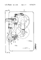
- FIG. 1 is a top plan view of rotary indexing apparatus according to the present invention.
- FIG. 2 is a side elevational view of that shown in FIG. 1 taken on line 2--2.
- FIG. 3 is a top view on an enlarged scale with parts broken away of an indexing arm and cooperating plunger apparatus.
- FIG. 4 is a circuit diagram of a fail-safe circuit according to the present invention.
- the reference numeral 11 indicates a main shaft rotatable about its central axis 12 and passing through a support table 13.
- Main shaft 11 is supported in and extends through suitable anti-friction bearings 14-15 which are carried by the support table 13.
- a mirror support member 16 for receiving, in the case of a laser beam indexing operation, a suitable mirror 17 for receiving the output beam 18 of a suitable laser (not shown) and directing it at the desired angle.
- Main shaft 11 extends past the upper side of the support table 13 opposite to that of the mirror support member 16 and carries a plurality of outwardly extending, infinitely radially adjustable indexing arms 21a-b (only two are shown for convenience) disposed one above another.
- the indexing arms are all of the same length and may be keyed to fit a circumferential groove in the main shaft to prevent any axial movement up or down the shaft.
- the indexing arms may be further provided with clamping bolts 22 to permit radial adjustment when these bolts are loosened and to lock the indexing arms on the shaft when the clamping bolts are tightened.
- a suitable driving servo-motor 23 carried by the support table 13.
- the output shaft (not shown) of the servo-motor 23 is coupled to the shaft 11 through pulley wheels 24 and 25 and a drive belt 26.
- the servo-motor 23 may be of any conventional type such as a Foxboro-Jordan rotary actuator SMV630 that can selectably effect rotation through preselected angles and is provided internally with an output potentiometer 27 to provide an output signal indicative of rotation whenever its output shaft carrying pulley wheel 25 is rotated upon actuation of the motor.
- indexing arms may be mounted on the main shaft 11 by making main shaft 11 of sufficient length to take the desired number of indexing arms, one for each position to which main shaft 11 (and, hence, mirror 17 or the like) is to be indexed. Only two indexing arms are shown for simplicity.
- Each indexing arm is suitably formed to be mounted on shaft 11 and to be locked in any desired radial position. This may be easily accomplished by forming the end to be carried by main shaft 11 in a generally U-shape whereby a clamping bolt 22 or the like may be used to squeeze the legs of the U together and thereby lock the indexing arm on the main shaft 11.
- the end of each indexing arm remote from shaft 11 is provided with a preferably cone shaped recess 28 to receive a pin 31, the extreme end 32 of which is preferably hemispherical in shape.
- Pin 31 is carried at the extreme end of an extension 33 forming part of a pneumatically actuated plunger 34.
- the plunger 34 may be of conventional type wherein the application of pneumatic pressure at one end as by hose 35 causes the extension 33 to move in one direction and the application of pneumatic pressure, as by hose 36, causes the extension 33 to move in the opposite direction.
- Each plunger 34 is actuated through a separate solenoid actuated pneumatic switch 45 effective to supply pneumatic pressure to the appropriate hose coupled to the plunger.
- Also carried by plunger 34 are magnetically actuated proximity switches 41 and 42. Switch 41 is actuated when the extension 33 is extended such that pin 31 is disposed in its recess 32, thereby providing an indication that a given indexing arm is locked in position.
- Switch 42 is actuated when extension 33 has moved toward the indexing arm, but has not as yet reached its desired distance of travel to provide an indication that the plunger associated with a given indexing arm has been actuated. It will be obvious to those skilled in the art that means other than that shown and described herein may be used to effect final positioning and locking of the indexing arms and provide indications of a completed step.
- a plunger and its associated components are provided for each indexing arm provided on main shaft 11.
- the plungers are most conveniently mounted on a supporting bracket 43 such that their pins 31 are each directly opposite the recess 28 in their associated indexing arms.
- the pins 31 do not need to be precisely oriented with respect to each other since, in each case, the main shaft 11 is rotated to its desired or necessary position, the appropriate indexing arm rotated and locked in position by its pin and then the indexing arm is locked to main shaft 11.
- potentiometer 44 At the upper end of shaft 11 is provided a potentiometer 44 that provides a signal indicative of the radial position or movement of shaft 11.
- the main shaft is rotated to the desired position so that the laser output beam is received by the mirror and reflected in precisely the desired direction.
- the indexing arm to control this position is then adjusted to receive in its recess the locking pin of its associated plunger.
- the plunger is then actuated to lock the indexing arm in position.
- the indexing arm is then locked to the main shaft. Thereafter, the mirror will always be precisely returned to this position when the servo-motor is actuated to bring the recess of the indexing arm opposite its associated locking pin.
- Any suitable and conventional means may be provided in conventional manner to selectably actuate and control the driving servo-motor to cause it to rotate the main shaft to a desired operative radial position. This will, of course, bring the tip of the appropriate indexing arm to approximately the desired operative position whereby the hemispherically-shaped tip of the appropriate plunger is aligned to enter its associated indexing arm recess.
- the appropriate indexing arm has reached approximately its operative position as noted above, its plunger is actuated to cause its hemispherical tip to enter the recess of the indexing arm and thereby cause it to be moved by the amount necessary to move it, and, hence, the mirror to precisely the desired operative position.
- the laser power control circuitry is disabled unless, for each indexed position, there has been received by an and gate or the like implemented using conventional electronic circuitry or, alternately, programmable controller software the servo-motor signal indicating it has been actuated, the main shaft signal indicating that the main shaft has been rotated, and the two plunger signals indicating that the correct plunger has been actuated and that its pin is in the recess of the indexing arm.
- the above-described failsafe circuitry may comprise a conventional and gate 51 for receiving an output signal from the servo-motor potentiometer 27, the main shaft potentiometer 44, and the proximity switch 41.
- the and gate 51 When all three output signals have been received by the and gate 51, it is actuated and supplies an output signal to the laser power control circuitry.
- the laser power control circuitry is disabled and prevents the generation of an output laser beam until the and gate output signal is received thereby indicating that the laser beam directing mirror has been indexed precisely to a predetermined desired position and has been locked in that position.
- the laser power control circuitry may be programmably controlled wherein the output signals of the potentiometers and switch are processed by the power control circuitry to permit actuation of the laser when, inter alia, the directing mirror has been indexed to and locked in a predetermined desired position.
Landscapes
- Physics & Mathematics (AREA)
- Optics & Photonics (AREA)
- Engineering & Computer Science (AREA)
- Mechanical Engineering (AREA)
- Plasma & Fusion (AREA)
- Laser Beam Processing (AREA)
Abstract
Description
Claims (7)
Priority Applications (1)
| Application Number | Priority Date | Filing Date | Title |
|---|---|---|---|
| US06/460,157 US4476374A (en) | 1983-01-24 | 1983-01-24 | Rotary indexing laser mirror apparatus |
Applications Claiming Priority (1)
| Application Number | Priority Date | Filing Date | Title |
|---|---|---|---|
| US06/460,157 US4476374A (en) | 1983-01-24 | 1983-01-24 | Rotary indexing laser mirror apparatus |
Publications (1)
| Publication Number | Publication Date |
|---|---|
| US4476374A true US4476374A (en) | 1984-10-09 |
Family
ID=23827587
Family Applications (1)
| Application Number | Title | Priority Date | Filing Date |
|---|---|---|---|
| US06/460,157 Expired - Fee Related US4476374A (en) | 1983-01-24 | 1983-01-24 | Rotary indexing laser mirror apparatus |
Country Status (1)
| Country | Link |
|---|---|
| US (1) | US4476374A (en) |
Cited By (1)
| Publication number | Priority date | Publication date | Assignee | Title |
|---|---|---|---|---|
| US6566629B1 (en) * | 1997-02-25 | 2003-05-20 | Lsp Technologies, Inc. | Hidden surface laser shock processing |
Citations (3)
| Publication number | Priority date | Publication date | Assignee | Title |
|---|---|---|---|---|
| US3131456A (en) * | 1960-03-30 | 1964-05-05 | Henry E Bryant | Safety control for a chucking machine |
| US3336823A (en) * | 1966-09-28 | 1967-08-22 | Babcock & Wilcox Co | Precision rotary work table |
| US4050355A (en) * | 1976-08-16 | 1977-09-27 | Kennametal Inc. | Indexing device |
-
1983
- 1983-01-24 US US06/460,157 patent/US4476374A/en not_active Expired - Fee Related
Patent Citations (3)
| Publication number | Priority date | Publication date | Assignee | Title |
|---|---|---|---|---|
| US3131456A (en) * | 1960-03-30 | 1964-05-05 | Henry E Bryant | Safety control for a chucking machine |
| US3336823A (en) * | 1966-09-28 | 1967-08-22 | Babcock & Wilcox Co | Precision rotary work table |
| US4050355A (en) * | 1976-08-16 | 1977-09-27 | Kennametal Inc. | Indexing device |
Cited By (1)
| Publication number | Priority date | Publication date | Assignee | Title |
|---|---|---|---|---|
| US6566629B1 (en) * | 1997-02-25 | 2003-05-20 | Lsp Technologies, Inc. | Hidden surface laser shock processing |
Similar Documents
| Publication | Publication Date | Title |
|---|---|---|
| US4687901A (en) | Machine tool for cutting or the like | |
| US4653739A (en) | Work positioner | |
| US4081179A (en) | Circle cutter | |
| US5108117A (en) | Workpart chuck positioning mechanism with independent shoes | |
| US4570842A (en) | Conduit weld positioner with arc length adjustor | |
| US5213348A (en) | Workpart chuck positioning mechanism with independent shoes | |
| US4476374A (en) | Rotary indexing laser mirror apparatus | |
| US5484982A (en) | Beam axis adjusting method for a laser robot | |
| EP0131366B1 (en) | Grinding machine with cnc pivotable workhead | |
| US3827685A (en) | Cam stop positioning apparatus | |
| CA1041403A (en) | Saw for cutting truss members, rafters and the like with dimensional accuracy | |
| US3672651A (en) | Adjustable mount | |
| US3684939A (en) | Automatic positioning accessory for numerical control machine tools | |
| US20050204879A1 (en) | Automated boring bar | |
| US4998383A (en) | Means for resetting a cylindrical grinding machine | |
| JP2004114203A (en) | Apparatus for measuring profile of workpiece and profile measuring system using the same | |
| US4586294A (en) | Machine tools | |
| JPH0417991A (en) | Device for centering nozzle of laser beam machine | |
| US4111075A (en) | Grinding machine | |
| JPH0310760A (en) | Wire saw for cutting crystalline brittle material | |
| US3678781A (en) | Adjustable throw eccentric | |
| JPS63171285A (en) | Output center for laser process treatment | |
| US2553570A (en) | Facing device | |
| US2908804A (en) | Universal spot welder | |
| US5018309A (en) | Universal grinder |
Legal Events
| Date | Code | Title | Description |
|---|---|---|---|
| AS | Assignment |
Owner name: AVCO EVERETT RESEARCH LABORATORY, INC. 2385 REVER Free format text: ASSIGNMENT OF ASSIGNORS INTEREST.;ASSIGNOR:SAGGESE, JOSEPH P.;REEL/FRAME:004105/0360 Effective date: 19830119 |
|
| AS | Assignment |
Owner name: COMBUSTION ENGINEERING, INC., 900 LONG RIDGE ROAD, Free format text: ASSIGNMENT OF ASSIGNORS INTEREST.;ASSIGNOR:AVCO EVERETT RESEARCH LABORATORY, INC. A CORP OF DE;REEL/FRAME:004289/0545 Effective date: 19840719 Owner name: COMBUSTION ENGINEERING, INC.,CONNECTICUT Free format text: ASSIGNMENT OF ASSIGNORS INTEREST;ASSIGNOR:AVCO EVERETT RESEARCH LABORATORY, INC. A CORP OF DE;REEL/FRAME:004289/0545 Effective date: 19840719 |
|
| FEPP | Fee payment procedure |
Free format text: PAYOR NUMBER ASSIGNED (ORIGINAL EVENT CODE: ASPN); ENTITY STATUS OF PATENT OWNER: LARGE ENTITY |
|
| FPAY | Fee payment |
Year of fee payment: 4 |
|
| REMI | Maintenance fee reminder mailed | ||
| LAPS | Lapse for failure to pay maintenance fees | ||
| FP | Lapsed due to failure to pay maintenance fee |
Effective date: 19921011 |
|
| STCH | Information on status: patent discontinuation |
Free format text: PATENT EXPIRED DUE TO NONPAYMENT OF MAINTENANCE FEES UNDER 37 CFR 1.362 |