US4474147A - Combined fire ring and carbon scraping insert - Google Patents
Combined fire ring and carbon scraping insert Download PDFInfo
- Publication number
- US4474147A US4474147A US06/329,574 US32957481A US4474147A US 4474147 A US4474147 A US 4474147A US 32957481 A US32957481 A US 32957481A US 4474147 A US4474147 A US 4474147A
- Authority
- US
- United States
- Prior art keywords
- cylinder
- leg
- cylinder head
- engine block
- fire ring
- Prior art date
- Legal status (The legal status is an assumption and is not a legal conclusion. Google has not performed a legal analysis and makes no representation as to the accuracy of the status listed.)
- Expired - Fee Related
Links
- 238000007790 scraping Methods 0.000 title claims abstract description 7
- OKTJSMMVPCPJKN-UHFFFAOYSA-N Carbon Chemical compound [C] OKTJSMMVPCPJKN-UHFFFAOYSA-N 0.000 title claims description 7
- 229910052799 carbon Inorganic materials 0.000 title claims description 7
- 239000011324 bead Substances 0.000 claims description 18
- 239000002184 metal Substances 0.000 claims description 3
- 238000002485 combustion reaction Methods 0.000 claims description 2
- 238000007789 sealing Methods 0.000 claims 1
- 229910000975 Carbon steel Inorganic materials 0.000 description 1
- 238000009825 accumulation Methods 0.000 description 1
- 230000015572 biosynthetic process Effects 0.000 description 1
- 239000010962 carbon steel Substances 0.000 description 1
- 230000002950 deficient Effects 0.000 description 1
- 230000005923 long-lasting effect Effects 0.000 description 1
- 238000000034 method Methods 0.000 description 1
Images
Classifications
-
- F—MECHANICAL ENGINEERING; LIGHTING; HEATING; WEAPONS; BLASTING
- F02—COMBUSTION ENGINES; HOT-GAS OR COMBUSTION-PRODUCT ENGINE PLANTS
- F02F—CYLINDERS, PISTONS OR CASINGS, FOR COMBUSTION ENGINES; ARRANGEMENTS OF SEALINGS IN COMBUSTION ENGINES
- F02F1/00—Cylinders; Cylinder heads
-
- F—MECHANICAL ENGINEERING; LIGHTING; HEATING; WEAPONS; BLASTING
- F16—ENGINEERING ELEMENTS AND UNITS; GENERAL MEASURES FOR PRODUCING AND MAINTAINING EFFECTIVE FUNCTIONING OF MACHINES OR INSTALLATIONS; THERMAL INSULATION IN GENERAL
- F16J—PISTONS; CYLINDERS; SEALINGS
- F16J15/00—Sealings
- F16J15/02—Sealings between relatively-stationary surfaces
- F16J15/06—Sealings between relatively-stationary surfaces with solid packing compressed between sealing surfaces
- F16J15/08—Sealings between relatively-stationary surfaces with solid packing compressed between sealing surfaces with exclusively metal packing
- F16J15/0881—Sealings between relatively-stationary surfaces with solid packing compressed between sealing surfaces with exclusively metal packing the sealing effect being obtained by plastic deformation of the packing
-
- F—MECHANICAL ENGINEERING; LIGHTING; HEATING; WEAPONS; BLASTING
- F16—ENGINEERING ELEMENTS AND UNITS; GENERAL MEASURES FOR PRODUCING AND MAINTAINING EFFECTIVE FUNCTIONING OF MACHINES OR INSTALLATIONS; THERMAL INSULATION IN GENERAL
- F16J—PISTONS; CYLINDERS; SEALINGS
- F16J9/00—Piston-rings, e.g. non-metallic piston-rings, seats therefor; Ring sealings of similar construction
-
- F—MECHANICAL ENGINEERING; LIGHTING; HEATING; WEAPONS; BLASTING
- F02—COMBUSTION ENGINES; HOT-GAS OR COMBUSTION-PRODUCT ENGINE PLANTS
- F02F—CYLINDERS, PISTONS OR CASINGS, FOR COMBUSTION ENGINES; ARRANGEMENTS OF SEALINGS IN COMBUSTION ENGINES
- F02F1/00—Cylinders; Cylinder heads
- F02F2001/006—Cylinders; Cylinder heads having a ring at the inside of a liner or cylinder for preventing the deposit of carbon oil particles, e.g. oil scrapers
-
- F—MECHANICAL ENGINEERING; LIGHTING; HEATING; WEAPONS; BLASTING
- F02—COMBUSTION ENGINES; HOT-GAS OR COMBUSTION-PRODUCT ENGINE PLANTS
- F02F—CYLINDERS, PISTONS OR CASINGS, FOR COMBUSTION ENGINES; ARRANGEMENTS OF SEALINGS IN COMBUSTION ENGINES
- F02F1/00—Cylinders; Cylinder heads
- F02F1/24—Cylinder heads
- F02F2001/249—Cylinder heads with flame plate, e.g. insert in the cylinder head used as a thermal insulation between cylinder head and combustion chamber
Definitions
- This invention relates to a combined fire ring and carbon-scraping cylinder insert which simplifies engine assembly.
- the engine block or cylinder sleeve is provided with a bead raised above the surface of the block or sleeve around the perimeter of each cylinder.
- a flat annular fire ring is positioned on the engine block or cylinder sleeve during assembly to surround the cylinder at its upper end and to rest on the bead.
- the cylinder head is provided with grooves corresponding to the raised bead around the perimeter of each cylinder. After the fire rings are positioned, the cylinder head is placed on the block and fastened to the block securely. The bead on the block or cylinder sleeve forces a portion of the metal fire ring to conform to the contours of the groove in the cylinder head and a seal is formed.
- the above-mentioned problems of the prior art have been eliminated.
- the assembly of the engine has been facilitated, assembly time reduced, and effective seals ensured.
- the unitary structure of this invention not only achieves these desirable results with respect to effective seals and ease of assembly but also functions effectively as a carbon scraping insert.
- a further object of this invention is to provide a unitary structure which combines the functions of a fire ring and a cylinder insert.
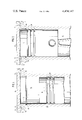
- FIG. 1 is a sectional elevation view showing one embodiment of this invention wherein a piston is at the bottom of its stroke within a cylinder.
- FIG. 2 is a sectional elevation view similar to FIG. 1 but showing the piston at the top of its stroke within a cylinder.
- FIGS. 1 and 2 there is shown a portion of an engine 10 in which this invention is incorporated.
- the illustrated portion of the invention includes a block 12 in which a plurality of cylinders are formed, one of which is shown at 14.
- a piston 16 operates within each cylinder and is provided with piston rings 18.
- the cylinder 14 is provided with a recess 20 at the upper end thereof.
- the engine block preferably has a bead 30 extending around the perimeter of each cylinder.
- Cylinder head 28 is provided to fit on top of the engine block and preferably has a groove 32 which corresponds to the bead on the engine block surrounding each cylinder.
- a unitary structure 24 which functions both as a fire ring and a carbon scraping insert.
- the unitary structure 24 is an annular element of L-shaped cross-section. It includes a first leg 22 which is positioned in recess 20 to scrape carbon from the walls of the piston 16 above the piston rings 18.
- the first leg 22 also serves to properly position second leg 26 of unitary structure 24 on the engine block 12 and holds the second leg 26 securely in position.
- cylinder head 28 is placed on the block 12 and fastened to the block by tightening bolts (not shown), the first leg 22 extending into the cylinder ensures that the second leg 26 is properly positioned to form a seal between the cylinder head and the engine block 12.
- the engine block bead 30 forces a portion of the second leg 26 of the unitary structure into the corresponding cylinder head groove to form a seal.
- the bead 30 is preferably taller than the cylinder head groove 32 is deep, but the bead and the groove may be of the same size.
- the ring of this invention is made of deformable metal, such as high quality carbon steel SAE 1008.
- the portion of the ring that functions as a fire ring is automatically positioned properly and is held securely in position by the other portion of the ring which extends in the cylinder and functions as a cylinder insert.
- the secure seal is ensured without the time consuming effort required to position a separate fire ring and without the possibility of damaging equipment which might otherwise occur with a separate fire ring and cylinder insert, since the portion of the unitary structure of this invention which functions as a fire ring can not be improperly positioned or jarred to an improper position during engine assembly.
Landscapes
- Engineering & Computer Science (AREA)
- General Engineering & Computer Science (AREA)
- Mechanical Engineering (AREA)
- Chemical & Material Sciences (AREA)
- Combustion & Propulsion (AREA)
- Cylinder Crankcases Of Internal Combustion Engines (AREA)
Abstract
A ring having an L-shaped cross section is provided for performing the functions of a fire ring, a carbon-scraping cylinder insert and for simplifying engine assembly. The ring ensures an effective seal between a cylinder head and an engine block or cylinder sleeve.
Description
1. Field of the Invention
This invention relates to a combined fire ring and carbon-scraping cylinder insert which simplifies engine assembly.
2. Description of the Prior Art
In high pressure internal combustion engines an effective long lasting seal at the upper end of a cylinder must be provided between the engine block and the cylinder head. In some engine designs a cylinder sleeve lines the cylinder with the top of the sleeve level with the engine block at the top of the cylinder. In engines having such a sleeve, the seal is actually formed between the cylinder head and the cylinder sleeve. Whether the seal is between the cylinder head and the engine block or between the cylinder head and the cylinder sleeve, it must be capable of withstanding both high temperatures and pressures. One arrangement for providing this seal is described in U.S. Pat. No. 3,586,338 to Ernest P. Miklau and John R. Crowe. The engine block or cylinder sleeve is provided with a bead raised above the surface of the block or sleeve around the perimeter of each cylinder. A flat annular fire ring is positioned on the engine block or cylinder sleeve during assembly to surround the cylinder at its upper end and to rest on the bead. The cylinder head is provided with grooves corresponding to the raised bead around the perimeter of each cylinder. After the fire rings are positioned, the cylinder head is placed on the block and fastened to the block securely. The bead on the block or cylinder sleeve forces a portion of the metal fire ring to conform to the contours of the groove in the cylinder head and a seal is formed.
Occasionally, problems have arisen during the fastening of the cylinder head to the engine block when a fire ring is positioned improperly or is moved out of position during the assembly process. If the fire ring's position is not corrected, an imperfect seal may be formed when the cylinder head is fastened onto the engine block or other engine parts, such as the cylinder sleeve, may crack. Apart from the possibility of defective seals or damage to engine parts, the prior art arrangement requires additional time-consuming effort to insure that each fire ring is placed in the precisely correct position to provide an effective seal.
Within an engine cylinder, carbon deposits form on piston walls above the piston rings and it is desirable to remove such deposits on a regular basis to prevent their accumulation. To accomplish this, an annular insert has been provided in a recess in the top of each cylinder, as illustrated in U.S. Pat. No. 3,489,130 to Harry L. Polidan and Norman M. Packard. The insert is positioned to scrape carbon deposits from the piston as the piston moves within the cylinder.
By the present invention the above-mentioned problems of the prior art have been eliminated. The assembly of the engine has been facilitated, assembly time reduced, and effective seals ensured. Moreover, the unitary structure of this invention not only achieves these desirable results with respect to effective seals and ease of assembly but also functions effectively as a carbon scraping insert.
Accordingly, it is an object of this invention to provide a unitary structure which is automatically positioned properly and securely to form a seal.
It is also an object of this invention to provide a unitary structure for forming a seal between the cylinder head and an engine block or cylinder sleeve which is easy to assemble.
A further object of this invention is to provide a unitary structure which combines the functions of a fire ring and a cylinder insert.
These objects are obtained, in one form of the invention, by providing a unitary structure in the form of a ring having an L-shaped cross section wherein one leg of the ring performs the functions of a fire ring and the other leg of the ring positions and holds the leg which functions as a fire ring in proper position during engine assembly and performs the functions of a cylinder insert.
FIG. 1 is a sectional elevation view showing one embodiment of this invention wherein a piston is at the bottom of its stroke within a cylinder.
FIG. 2 is a sectional elevation view similar to FIG. 1 but showing the piston at the top of its stroke within a cylinder.
In FIGS. 1 and 2 there is shown a portion of an engine 10 in which this invention is incorporated. The illustrated portion of the invention includes a block 12 in which a plurality of cylinders are formed, one of which is shown at 14. A piston 16 operates within each cylinder and is provided with piston rings 18. The cylinder 14 is provided with a recess 20 at the upper end thereof. The engine block preferably has a bead 30 extending around the perimeter of each cylinder. Cylinder head 28 is provided to fit on top of the engine block and preferably has a groove 32 which corresponds to the bead on the engine block surrounding each cylinder.
In accordance with this invention, a unitary structure 24 is provided which functions both as a fire ring and a carbon scraping insert. The unitary structure 24 is an annular element of L-shaped cross-section. It includes a first leg 22 which is positioned in recess 20 to scrape carbon from the walls of the piston 16 above the piston rings 18. The first leg 22 also serves to properly position second leg 26 of unitary structure 24 on the engine block 12 and holds the second leg 26 securely in position. When cylinder head 28 is placed on the block 12 and fastened to the block by tightening bolts (not shown), the first leg 22 extending into the cylinder ensures that the second leg 26 is properly positioned to form a seal between the cylinder head and the engine block 12. As the cylinder head is fastened to the engine block, the engine block bead 30 forces a portion of the second leg 26 of the unitary structure into the corresponding cylinder head groove to form a seal. The bead 30 is preferably taller than the cylinder head groove 32 is deep, but the bead and the groove may be of the same size. To enhance the formation of a seal, the ring of this invention is made of deformable metal, such as high quality carbon steel SAE 1008.
The description of this invention has been made with reference to an engine block having a raised bead surrounding each cylinder. In some engine designs a cylinder sleeve or liner is provided extending the length of the cylinder and being level with the engine block at the top of the cylinder. In such engines the raised bead may be provided on the top of the cylinder sleeve rather than on the engine block itself. When the cylinder head is fastened to the engine block, the raised bead on the cylinder liner forces a portion of the second leg 26 of the ring 24 into a corresponding groove provided in the cylinder head. The required seal is thereby formed between the cylinder head and the cylinder sleeve. By combining the fire ring and the cylinder insert into one unitary structure having an L-shaped cross-section, the portion of the ring that functions as a fire ring is automatically positioned properly and is held securely in position by the other portion of the ring which extends in the cylinder and functions as a cylinder insert. With this invention, the secure seal is ensured without the time consuming effort required to position a separate fire ring and without the possibility of damaging equipment which might otherwise occur with a separate fire ring and cylinder insert, since the portion of the unitary structure of this invention which functions as a fire ring can not be improperly positioned or jarred to an improper position during engine assembly.
Claims (4)
1. A combined fire ring and carbon-scraping cylinder insert for an internal combustion engine including an engine block having a cylinder formed therein and a cylinder head, said combined fire ring and carbon-scraping insert comprising:
a. an annular member of L-shaped cross-section;
b. said annular member comprising a first leg received in the upper end only of the cylinder and positioned to remove carbon from a piston moving in the cylinder;
c. said annular member further comprising a second leg extending radially outwardly from and substantially perpendicular to said first leg, said second leg providing a fire ring extending between the engine block and the cylinder head in sealing engagement therewith;
d. said first leg being received in a recess in the upper end of the cylinder to hold said second leg in fixed position between the block and the cylinder head; and
e. said second leg extending a substantial distance radially outwardly from said first leg to provide a substantial area of contact with the engine block and the cylinder head;
f. wherein said first and second legs are of substantially equal length and thickness.
2. A unitary structure as recited in claim 1 made of deformable metal.
3. A unitary structure as recited in claim 1 wherein a raised bead is provided on an engine block surrounding the cylinder into which said first leg extends and wherein a groove is provided in a cylinder head corresponding to said raised bead, said second leg being positioned over said raised bead on said engine block.
4. A unitary structure as recited in claim 1 wherein a raised bead is provided on a cylinder sleeve surrounding the cylinder into which said first leg extends and wherein a groove is provided in a cylinder head corresponding to said raised bead, said second leg being positioned over said raised bead on said cylinder sleeve.
Priority Applications (1)
| Application Number | Priority Date | Filing Date | Title |
|---|---|---|---|
| US06/329,574 US4474147A (en) | 1981-12-10 | 1981-12-10 | Combined fire ring and carbon scraping insert |
Applications Claiming Priority (1)
| Application Number | Priority Date | Filing Date | Title |
|---|---|---|---|
| US06/329,574 US4474147A (en) | 1981-12-10 | 1981-12-10 | Combined fire ring and carbon scraping insert |
Publications (1)
| Publication Number | Publication Date |
|---|---|
| US4474147A true US4474147A (en) | 1984-10-02 |
Family
ID=23286048
Family Applications (1)
| Application Number | Title | Priority Date | Filing Date |
|---|---|---|---|
| US06/329,574 Expired - Fee Related US4474147A (en) | 1981-12-10 | 1981-12-10 | Combined fire ring and carbon scraping insert |
Country Status (1)
| Country | Link |
|---|---|
| US (1) | US4474147A (en) |
Cited By (49)
| Publication number | Priority date | Publication date | Assignee | Title |
|---|---|---|---|---|
| DE3511837C1 (en) * | 1985-03-30 | 1986-11-27 | M.A.N.- B & W Diesel GmbH, 8900 Augsburg | Reciprocating internal combustion engine |
| FR2596458A1 (en) * | 1986-03-26 | 1987-10-02 | Man Nutzfahrzeuge Gmbh | SEALING DEVICE BETWEEN CYLINDER HEAD AND HOUSING ON A RECIPROCATING PISTON ENGINE |
| US4770133A (en) * | 1985-12-11 | 1988-09-13 | M A N Nutzfahrzeuge Gmbh | Cylinder liner for reciprocating-type internal combustion engines |
| FR2619599A1 (en) * | 1987-08-19 | 1989-02-24 | Man Nutzfahrzeuge Gmbh | SEALING DEVICE FOR CYLINDER CYLINDER HEAD COMBUSTION CHAMBER FOR AN RECIPROCATING PISTON ENGINE |
| US4949982A (en) * | 1988-06-13 | 1990-08-21 | Copeland Corporation | Compressor valve assembly |
| EP0407843A1 (en) * | 1989-07-12 | 1991-01-16 | MAN Nutzfahrzeuge Aktiengesellschaft | Cylinder gasket for an internal combustion engine |
| EP0483443A1 (en) * | 1989-06-02 | 1992-05-06 | Arne Remmerfelt | Resilient sealing means |
| US5112066A (en) * | 1990-12-05 | 1992-05-12 | Arne Remmerfelt | Resilient sealing ring |
| US5221097A (en) * | 1991-12-10 | 1993-06-22 | Ishikawa Gasket Co., Ltd. | Sealing system using metal gasket with projection bead |
| US5553585A (en) * | 1994-05-27 | 1996-09-10 | Wartsila Diesel International Ltd Oy | Anti-polishing ring |
| WO1997003280A1 (en) * | 1995-07-07 | 1997-01-30 | Man B & W Diesel A/S | An internal combustion engine having a coke scraping ring in a cylinder |
| EP0768459A1 (en) * | 1995-10-13 | 1997-04-16 | Scania Cv Aktiebolag | Device for sealing a combustion chamber of a combustion engine |
| WO1997018384A1 (en) * | 1995-11-14 | 1997-05-22 | John Brengle Taylor | Improvements in combustion engines |
| FR2763362A1 (en) * | 1997-05-13 | 1998-11-20 | Semt Pielstick | DEVICE FOR SCRAPING THE HEAD OF A PISTON |
| EP0995890A1 (en) * | 1998-10-20 | 2000-04-26 | Wärtsilä NSD Schweiz AG | Cylinder for an internal combustion engine |
| US6164260A (en) * | 1999-07-13 | 2000-12-26 | Caterpillar Inc. | Scraping ring and sealing ring used with a cylinder liner in an internal combustion engine |
| US6196179B1 (en) * | 1999-04-20 | 2001-03-06 | Daimlerchrysler Ag | Internal combustion engine |
| US6234134B1 (en) | 2000-06-20 | 2001-05-22 | General Electric Company | Internal combustion engine having integral anti-polishing ring |
| US6314937B1 (en) | 2000-06-20 | 2001-11-13 | General Electric Company | Internal combustion engine and method for controlling the production of oxides of nitrogen |
| US6367463B1 (en) * | 1999-06-04 | 2002-04-09 | Wartsila Nsd Oy Ab | Advanced antipolishing ring arrangement |
| DE10321034B3 (en) * | 2003-05-10 | 2005-01-13 | Daimlerchrysler Ag | Piston-type internal combustion engine, e.g. for vehicle, has insert fitted without play between cylinder liner and cylinder head |
| US20050172926A1 (en) * | 2004-02-06 | 2005-08-11 | Poola Ramesh B. | Large-bore, medium-speed diesel engine having piston crown bowl with acute re-entrant angle |
| US20060086327A1 (en) * | 2004-10-25 | 2006-04-27 | General Electric Company | Engine power assembly |
| US20070170661A1 (en) * | 2006-01-26 | 2007-07-26 | Amable Mancenido | Fire ring seal |
| WO2008074277A1 (en) | 2006-12-20 | 2008-06-26 | Mahle International Gmbh | Insert for a cylinder sleeve or for a cylinder of an internal combustion engine |
| EP2243940A1 (en) * | 2009-04-06 | 2010-10-27 | Wärtsilä Schweiz AG | Reduction device for reducing gas pressure in the piston ring package of a hydraulic piston combustion engine |
| US20100307443A1 (en) * | 2009-06-04 | 2010-12-09 | Darrel Sand | Zero ridge cylinder bore |
| US20110139113A1 (en) * | 2009-12-11 | 2011-06-16 | Caterpillar Inc. | Compound Sealing Mechanism, Cylinder Liner, And Engine Assembly Method |
| WO2011159231A1 (en) * | 2010-06-16 | 2011-12-22 | Scania Cv Ab | Arrangement in a combustion engine |
| DE102011012507A1 (en) | 2011-02-25 | 2012-08-30 | Ks Kolbenschmidt Gmbh | Annular element for cylinder of internal combustion engine, has annular portion including inner section that is set to deviate from circular shape such that annular portion is fitted into circular groove of cylinder line |
| US20120304954A1 (en) * | 2011-06-02 | 2012-12-06 | Caterpillar Inc. | Cylinder liner with a case on a cuff-ring groove |
| US20150114373A1 (en) * | 2012-04-20 | 2015-04-30 | International Engine Intellectual Property Company , Llc | Carbon scraping ring with abradable coating |
| WO2015134162A1 (en) * | 2014-03-03 | 2015-09-11 | Cummins, Inc. | Carbon scraper |
| US20160090938A1 (en) * | 2014-09-26 | 2016-03-31 | Caterpillar Inc. | Internal Combustion Engine Cylinder Flow Deflector |
| CN105484889A (en) * | 2016-01-28 | 2016-04-13 | 江苏科技大学 | Combined cylinder liner |
| EP3043054A1 (en) * | 2015-01-09 | 2016-07-13 | Caterpillar Motoren GmbH & Co. KG | Cuff-ring for a cylinder liner |
| CN107387252A (en) * | 2017-09-13 | 2017-11-24 | 中原内配集团股份有限公司 | A kind of dry liner and preparation method thereof |
| CN107630762A (en) * | 2017-09-13 | 2018-01-26 | 中原内配集团股份有限公司 | A kind of dry liner and preparation method thereof |
| US20180266359A1 (en) * | 2017-03-20 | 2018-09-20 | International Engine Intellectual Property Company, Llc | Piston scraping ring with power groove |
| EP3540202A1 (en) * | 2018-03-14 | 2019-09-18 | Winterthur Gas & Diesel Ltd. | Sealing ring, cylinder for a combustion engine, combustion engine, method for producing a cylinder and use of a sealing ring |
| US20200040857A1 (en) * | 2018-08-01 | 2020-02-06 | Ford Global Technologies, Llc | Fuel injector with duct assembly |
| WO2021126509A1 (en) * | 2019-12-17 | 2021-06-24 | Cummins Inc. | Compound diameter carbon scraper ring |
| AT524214B1 (en) * | 2020-10-08 | 2022-04-15 | Avl List Gmbh | Internal combustion engine with cylinder head gasket |
| US11313467B1 (en) | 2021-01-21 | 2022-04-26 | Total Seal, Inc. | Piston ring seals |
| US11428189B1 (en) * | 2021-05-12 | 2022-08-30 | Caterpillar Inc. | Piston bowl geometry, cuff and top land interaction for reduced hydrocarbons, improved combustion efficiency, and piston temperature |
| US11767803B2 (en) | 2020-07-13 | 2023-09-26 | Powerhouse Engine Solutions Switzerland IP Holding GmbH | Internal combustion engine system |
| US11920538B2 (en) * | 2020-05-27 | 2024-03-05 | Cummins Inc. | Anti-polish ring for an engine cylinder |
| US12000354B2 (en) * | 2022-04-13 | 2024-06-04 | Isuzu Motors Limited | Internal combustion engine |
| US20250109794A1 (en) * | 2022-01-24 | 2025-04-03 | Mitsubishi Heavy Industries Engine & Turbocharger, Ltd. | Gas sealing structure for internal combustion engine |
Citations (9)
| Publication number | Priority date | Publication date | Assignee | Title |
|---|---|---|---|---|
| US321145A (en) * | 1885-06-30 | Chaeles p | ||
| US2109814A (en) * | 1936-11-09 | 1938-03-01 | Detroit Gasket & Mfg Co | Gasket |
| US2641381A (en) * | 1948-11-18 | 1953-06-09 | Hydropress Inc | Sealing means for pressure vessels |
| US3080171A (en) * | 1960-02-19 | 1963-03-05 | Lionel Pacific Inc | Flange seal |
| US3476099A (en) * | 1968-02-26 | 1969-11-04 | Int Harvester Co | Head,gasket,and protector assembly and method |
| US3489130A (en) * | 1968-01-10 | 1970-01-13 | Sealed Power Corp | Piston and cylinder construction |
| GB1215111A (en) * | 1968-02-06 | 1970-12-09 | Sulzer Ag | Improvements in or relating to internal combustion engines |
| US3586338A (en) * | 1969-05-29 | 1971-06-22 | Mack Trucks | Combustion seal for engines |
| US3920252A (en) * | 1973-05-21 | 1975-11-18 | Jacques Dechavanne | Dynamic seal for double-acting piston |
-
1981
- 1981-12-10 US US06/329,574 patent/US4474147A/en not_active Expired - Fee Related
Patent Citations (9)
| Publication number | Priority date | Publication date | Assignee | Title |
|---|---|---|---|---|
| US321145A (en) * | 1885-06-30 | Chaeles p | ||
| US2109814A (en) * | 1936-11-09 | 1938-03-01 | Detroit Gasket & Mfg Co | Gasket |
| US2641381A (en) * | 1948-11-18 | 1953-06-09 | Hydropress Inc | Sealing means for pressure vessels |
| US3080171A (en) * | 1960-02-19 | 1963-03-05 | Lionel Pacific Inc | Flange seal |
| US3489130A (en) * | 1968-01-10 | 1970-01-13 | Sealed Power Corp | Piston and cylinder construction |
| GB1215111A (en) * | 1968-02-06 | 1970-12-09 | Sulzer Ag | Improvements in or relating to internal combustion engines |
| US3476099A (en) * | 1968-02-26 | 1969-11-04 | Int Harvester Co | Head,gasket,and protector assembly and method |
| US3586338A (en) * | 1969-05-29 | 1971-06-22 | Mack Trucks | Combustion seal for engines |
| US3920252A (en) * | 1973-05-21 | 1975-11-18 | Jacques Dechavanne | Dynamic seal for double-acting piston |
Cited By (70)
| Publication number | Priority date | Publication date | Assignee | Title |
|---|---|---|---|---|
| DE3511837C1 (en) * | 1985-03-30 | 1986-11-27 | M.A.N.- B & W Diesel GmbH, 8900 Augsburg | Reciprocating internal combustion engine |
| US4770133A (en) * | 1985-12-11 | 1988-09-13 | M A N Nutzfahrzeuge Gmbh | Cylinder liner for reciprocating-type internal combustion engines |
| FR2596458A1 (en) * | 1986-03-26 | 1987-10-02 | Man Nutzfahrzeuge Gmbh | SEALING DEVICE BETWEEN CYLINDER HEAD AND HOUSING ON A RECIPROCATING PISTON ENGINE |
| FR2619599A1 (en) * | 1987-08-19 | 1989-02-24 | Man Nutzfahrzeuge Gmbh | SEALING DEVICE FOR CYLINDER CYLINDER HEAD COMBUSTION CHAMBER FOR AN RECIPROCATING PISTON ENGINE |
| US4949982A (en) * | 1988-06-13 | 1990-08-21 | Copeland Corporation | Compressor valve assembly |
| EP0483443A1 (en) * | 1989-06-02 | 1992-05-06 | Arne Remmerfelt | Resilient sealing means |
| EP0407843A1 (en) * | 1989-07-12 | 1991-01-16 | MAN Nutzfahrzeuge Aktiengesellschaft | Cylinder gasket for an internal combustion engine |
| US5112066A (en) * | 1990-12-05 | 1992-05-12 | Arne Remmerfelt | Resilient sealing ring |
| US5221097A (en) * | 1991-12-10 | 1993-06-22 | Ishikawa Gasket Co., Ltd. | Sealing system using metal gasket with projection bead |
| US5553585A (en) * | 1994-05-27 | 1996-09-10 | Wartsila Diesel International Ltd Oy | Anti-polishing ring |
| WO1997003280A1 (en) * | 1995-07-07 | 1997-01-30 | Man B & W Diesel A/S | An internal combustion engine having a coke scraping ring in a cylinder |
| JP3202243B2 (en) | 1995-07-07 | 2001-08-27 | マーン・ベー・オグ・ドバルドヴェー・ディーゼール・アクティーゼルスカブ | Internal combustion engine with coke scraping ring in cylinder |
| CN1080821C (en) * | 1995-07-07 | 2002-03-13 | 曼B与W狄赛尔公司 | Internal combustion engine having coke scraping ring in cylinder |
| EP0768459A1 (en) * | 1995-10-13 | 1997-04-16 | Scania Cv Aktiebolag | Device for sealing a combustion chamber of a combustion engine |
| US5752480A (en) * | 1995-10-13 | 1998-05-19 | Scania Cv Aktiebolac | Device for sealing a combustion chamber of a combustion engine |
| WO1997018384A1 (en) * | 1995-11-14 | 1997-05-22 | John Brengle Taylor | Improvements in combustion engines |
| FR2763362A1 (en) * | 1997-05-13 | 1998-11-20 | Semt Pielstick | DEVICE FOR SCRAPING THE HEAD OF A PISTON |
| EP0995890A1 (en) * | 1998-10-20 | 2000-04-26 | Wärtsilä NSD Schweiz AG | Cylinder for an internal combustion engine |
| US6196179B1 (en) * | 1999-04-20 | 2001-03-06 | Daimlerchrysler Ag | Internal combustion engine |
| US6367463B1 (en) * | 1999-06-04 | 2002-04-09 | Wartsila Nsd Oy Ab | Advanced antipolishing ring arrangement |
| US6164260A (en) * | 1999-07-13 | 2000-12-26 | Caterpillar Inc. | Scraping ring and sealing ring used with a cylinder liner in an internal combustion engine |
| WO2001004519A1 (en) | 1999-07-13 | 2001-01-18 | Caterpillar Inc. | Scraping ring and sealing ring used with a cylinder liner in an internal combustion engine |
| US6314937B1 (en) | 2000-06-20 | 2001-11-13 | General Electric Company | Internal combustion engine and method for controlling the production of oxides of nitrogen |
| US6234134B1 (en) | 2000-06-20 | 2001-05-22 | General Electric Company | Internal combustion engine having integral anti-polishing ring |
| DE10321034B3 (en) * | 2003-05-10 | 2005-01-13 | Daimlerchrysler Ag | Piston-type internal combustion engine, e.g. for vehicle, has insert fitted without play between cylinder liner and cylinder head |
| US7438039B2 (en) | 2004-02-06 | 2008-10-21 | Electro-Motive Diesel, Inc. | Large-bore, medium-speed diesel engine having piston crown bowl with acute re-entrant angle |
| US20050172926A1 (en) * | 2004-02-06 | 2005-08-11 | Poola Ramesh B. | Large-bore, medium-speed diesel engine having piston crown bowl with acute re-entrant angle |
| US20090039605A1 (en) * | 2004-02-06 | 2009-02-12 | Poola Ramesh B | Large-bore, medium-speed diesel engine having piston crown bowl with acute re-entrant angle |
| US20060086327A1 (en) * | 2004-10-25 | 2006-04-27 | General Electric Company | Engine power assembly |
| US20070170661A1 (en) * | 2006-01-26 | 2007-07-26 | Amable Mancenido | Fire ring seal |
| WO2008074277A1 (en) | 2006-12-20 | 2008-06-26 | Mahle International Gmbh | Insert for a cylinder sleeve or for a cylinder of an internal combustion engine |
| US20080150237A1 (en) * | 2006-12-20 | 2008-06-26 | Ulrich Bischofberger | Insert for a cylinder sleeve or a cylinder of an internal combustion engine |
| US7484493B2 (en) | 2006-12-20 | 2009-02-03 | Mahle International Gmbh | Insert for a cylinder sleeve or a cylinder of an internal combustion engine |
| EP2243940A1 (en) * | 2009-04-06 | 2010-10-27 | Wärtsilä Schweiz AG | Reduction device for reducing gas pressure in the piston ring package of a hydraulic piston combustion engine |
| US20100307443A1 (en) * | 2009-06-04 | 2010-12-09 | Darrel Sand | Zero ridge cylinder bore |
| US8413632B2 (en) * | 2009-06-04 | 2013-04-09 | Darrel Sand | Zero ridge cylinder bore |
| DE112010004758T5 (en) | 2009-12-11 | 2012-10-18 | Caterpillar Inc. | Composite gasket, cylinder liner and assembly process for a motor |
| US20110139113A1 (en) * | 2009-12-11 | 2011-06-16 | Caterpillar Inc. | Compound Sealing Mechanism, Cylinder Liner, And Engine Assembly Method |
| RU2528227C1 (en) * | 2010-06-16 | 2014-09-10 | Сканиа Св Аб | Ice design |
| CN102933827A (en) * | 2010-06-16 | 2013-02-13 | 斯堪尼亚商用车有限公司 | Arrangement in a combustion engine |
| WO2011159231A1 (en) * | 2010-06-16 | 2011-12-22 | Scania Cv Ab | Arrangement in a combustion engine |
| CN102933827B (en) * | 2010-06-16 | 2018-03-30 | 斯堪尼亚商用车有限公司 | Device in internal combustion engine |
| DE102011012507A1 (en) | 2011-02-25 | 2012-08-30 | Ks Kolbenschmidt Gmbh | Annular element for cylinder of internal combustion engine, has annular portion including inner section that is set to deviate from circular shape such that annular portion is fitted into circular groove of cylinder line |
| DE102011012507B4 (en) * | 2011-02-25 | 2014-11-27 | Ks Kolbenschmidt Gmbh | Function-optimized design of a ring element for cylinders of an internal combustion engine |
| US20120304954A1 (en) * | 2011-06-02 | 2012-12-06 | Caterpillar Inc. | Cylinder liner with a case on a cuff-ring groove |
| CN103649507A (en) * | 2011-06-02 | 2014-03-19 | 卡特彼勒公司 | Cylinder liner with a case on a cuff-ring groove |
| US20150114373A1 (en) * | 2012-04-20 | 2015-04-30 | International Engine Intellectual Property Company , Llc | Carbon scraping ring with abradable coating |
| US9562491B2 (en) * | 2012-04-20 | 2017-02-07 | International Engine Intellectual Property Company, Llc. | Carbon scraping ring with abradable coating |
| WO2015134162A1 (en) * | 2014-03-03 | 2015-09-11 | Cummins, Inc. | Carbon scraper |
| US9822702B2 (en) | 2014-03-03 | 2017-11-21 | Cummins, Inc. | Carbon scraper |
| US9638131B2 (en) * | 2014-09-26 | 2017-05-02 | Caterpillar Inc. | Internal combustion engine cylinder flow deflector |
| US20160090938A1 (en) * | 2014-09-26 | 2016-03-31 | Caterpillar Inc. | Internal Combustion Engine Cylinder Flow Deflector |
| EP3043054A1 (en) * | 2015-01-09 | 2016-07-13 | Caterpillar Motoren GmbH & Co. KG | Cuff-ring for a cylinder liner |
| CN105484889A (en) * | 2016-01-28 | 2016-04-13 | 江苏科技大学 | Combined cylinder liner |
| US20180266359A1 (en) * | 2017-03-20 | 2018-09-20 | International Engine Intellectual Property Company, Llc | Piston scraping ring with power groove |
| US10487779B2 (en) * | 2017-03-20 | 2019-11-26 | International Engine Intellectual Property Company, Llc. | Piston scraping ring with power groove |
| CN107387252A (en) * | 2017-09-13 | 2017-11-24 | 中原内配集团股份有限公司 | A kind of dry liner and preparation method thereof |
| CN107630762A (en) * | 2017-09-13 | 2018-01-26 | 中原内配集团股份有限公司 | A kind of dry liner and preparation method thereof |
| EP3540202A1 (en) * | 2018-03-14 | 2019-09-18 | Winterthur Gas & Diesel Ltd. | Sealing ring, cylinder for a combustion engine, combustion engine, method for producing a cylinder and use of a sealing ring |
| US20200040857A1 (en) * | 2018-08-01 | 2020-02-06 | Ford Global Technologies, Llc | Fuel injector with duct assembly |
| US11466651B2 (en) * | 2018-08-01 | 2022-10-11 | Ford Global Technologies, Llc | Fuel injector with duct assembly |
| WO2021126509A1 (en) * | 2019-12-17 | 2021-06-24 | Cummins Inc. | Compound diameter carbon scraper ring |
| US11920538B2 (en) * | 2020-05-27 | 2024-03-05 | Cummins Inc. | Anti-polish ring for an engine cylinder |
| US11767803B2 (en) | 2020-07-13 | 2023-09-26 | Powerhouse Engine Solutions Switzerland IP Holding GmbH | Internal combustion engine system |
| AT524214B1 (en) * | 2020-10-08 | 2022-04-15 | Avl List Gmbh | Internal combustion engine with cylinder head gasket |
| AT524214A4 (en) * | 2020-10-08 | 2022-04-15 | Avl List Gmbh | Internal combustion engine with cylinder head gasket |
| US11313467B1 (en) | 2021-01-21 | 2022-04-26 | Total Seal, Inc. | Piston ring seals |
| US11428189B1 (en) * | 2021-05-12 | 2022-08-30 | Caterpillar Inc. | Piston bowl geometry, cuff and top land interaction for reduced hydrocarbons, improved combustion efficiency, and piston temperature |
| US20250109794A1 (en) * | 2022-01-24 | 2025-04-03 | Mitsubishi Heavy Industries Engine & Turbocharger, Ltd. | Gas sealing structure for internal combustion engine |
| US12000354B2 (en) * | 2022-04-13 | 2024-06-04 | Isuzu Motors Limited | Internal combustion engine |
Similar Documents
| Publication | Publication Date | Title |
|---|---|---|
| US4474147A (en) | Combined fire ring and carbon scraping insert | |
| US6036194A (en) | Combustion gas seal for an internal combustion engine | |
| US3586338A (en) | Combustion seal for engines | |
| GB2189853A (en) | Reciprocating engine | |
| US3942807A (en) | Sealing arrangement | |
| JPH05209553A (en) | Sealed structure of cylinder liner | |
| WO1998011365A9 (en) | Combustion gas seal for an internal combustion engine | |
| US6488000B2 (en) | Cylinder block for an internal combustion engine | |
| RU1838649C (en) | Sealing of cylinder head of piston machine, mainly internal combustion engine | |
| US20240401552A1 (en) | Injector cup for engines apparatus and methods of use | |
| US4727833A (en) | Sealing structure of cylinder head cover | |
| EP1387113A3 (en) | Metal gasket with a seal ring | |
| US2972341A (en) | Means for sealing the cylinder heads of internal combustion engines | |
| US4384729A (en) | Interlocking dual plane gapped compression rings | |
| US6196179B1 (en) | Internal combustion engine | |
| US5743535A (en) | Compression piston ring seal | |
| US5377643A (en) | Cylinder head sealing device for an internal combustion engine | |
| WO1984004357A1 (en) | Unitary installation of engine cylinder liner, piston and rod | |
| US4346646A (en) | Piston for internal combustion engines | |
| US3463056A (en) | Combustion seal for cylinder liner in internal combustion engines | |
| US4099725A (en) | Seal of the upper area of a wet cylinder liner | |
| US3992980A (en) | Internal oil seal for piston | |
| US3459166A (en) | Valve spring retainer and valve stem oil shield assembly and method of assembly | |
| US4068563A (en) | Internal oil seal for piston | |
| US6584947B2 (en) | Cylinder head gasket |
Legal Events
| Date | Code | Title | Description |
|---|---|---|---|
| AS | Assignment |
Owner name: MACK TRUCKS, INC., Free format text: ASSIGNMENT OF ASSIGNORS INTEREST.;ASSIGNOR:HOOPES, TED R.;REEL/FRAME:003968/0224 Effective date: 19811130 |
|
| REMI | Maintenance fee reminder mailed | ||
| LAPS | Lapse for failure to pay maintenance fees | ||
| STCH | Information on status: patent discontinuation |
Free format text: PATENT EXPIRED DUE TO NONPAYMENT OF MAINTENANCE FEES UNDER 37 CFR 1.362 |
|
| FP | Lapsed due to failure to pay maintenance fee |
Effective date: 19881002 |
|
| FEPP | Fee payment procedure |
Free format text: PAYOR NUMBER ASSIGNED (ORIGINAL EVENT CODE: ASPN); ENTITY STATUS OF PATENT OWNER: LARGE ENTITY |