Technisches GebietTechnical area
Die vorliegende Offenbarung betrifft allgemein die Ausgestaltung von Verbrennungsdichtungen für Verbrennungsmotoren. Insbesondere betrifft sie die Ausbildung einer Verbrennungsdichtung mit Hilfe eines einteiligen Dichtungskörpers, der dazu gebildet ist, einen schützenden Endvorsprung einer Zylinderlaufbuchse aufzunehmen.The present disclosure generally relates to the design of combustion seals for internal combustion engines. In particular, it relates to the formation of a combustion seal by means of a one-piece seal body adapted to receive a protective end projection of a cylinder liner.
Hintergrundbackground
Im Zusammenhang mit Zylindern von Verbrennungsmotoren kommen unterschiedlichste Herangehensweisen für eine Abdichtung zur Anwendung. Die Verwendung einer Zylinderkopfdichtung, die darin ausgebildete Fluiddurchlassöffnungen zum Abdichten von Fluiddurchlasskanälen zwischen einem Motorgehäuse und einem Motorkopf aufweist, ist seit langem im Stand der Technik bekannt. In vielen herkömmlichen Motoren kommt auch eine separate zwischen dem Motorkopf und dem Motorgehäuse angeordnete Verbrennungsdichtung zur Anwendung, die zwischen dem Motorkopf und dem Motorgehäuse oder einer Zylinderlaufbuchse zum Auffangen von Verbrennungsgasen abdichtet. Die Zylinderkopfdichtung kann als ein von der Verbrennungsdichtung separates Teil ausgebildet sein und umgibt die Verbrennungsdichtung, wenn sie in einem Motor betriebsbereit angeordnet wird. Die Zylinderkopfdichtung und die Verbrennungsdichtung können beide relativ hohen Dichtungslasten ausgesetzt sein, um es den Bauteilen zu ermöglichen, relativ hohen Verbrennungsdrücken und Temperaturen standzuhalten, ohne dass es zu Verformungen oder einem Versagen kommt. In der Hochdruckumgebung von Kompressionszündungsmotoren können eine robuste Ausgestaltung und ein Abdichten von solchen Bauteilen besonders gewünscht sein. Während bestimmte Herangehensweisen für die Ausgestaltung und die Anwendung von Zylinderkopfdichtungen und Verbrennungsdichtungen für viele Jahre erfolgreich waren, weisen diese in der Regel bestimmte Nachteile auf.In the context of cylinders of internal combustion engines various approaches for a seal are used. The use of a cylinder head gasket having fluid passage openings formed therein for sealing fluid passageways between a motor housing and an engine head has long been known in the art. In many conventional engines, a separate combustion seal disposed between the engine head and the engine housing is used, which seals between the engine head and the engine housing or a cylinder liner for capturing combustion gases. The cylinder head gasket may be formed as a separate part from the combustion gasket and surrounds the combustion gasket when it is operatively disposed in an engine. The cylinder head gasket and the combustion gasket may both be exposed to relatively high sealing loads to allow the components to withstand relatively high combustion pressures and temperatures without causing deformation or failure. In the high pressure environment of compression ignition engines, a robust design and sealing of such components may be particularly desirable. While certain approaches to the design and use of cylinder head gaskets and combustion gaskets have been successful for many years, these typically have certain disadvantages.
Das US-Patent 4,474,147 von Hoopes offenbart ein Beispiel einer Dichtungsvorrichtung für einen Motor. Die Dichtung enthält einen Ring, der angeblich dazu fähig ist, eine effektive Abdichtung in einem Motorblock oder einer Zylinderlaufbuchse sicherzustellen. Während die Vorrichtung von Hoopes in bestimmten Umgebungen effektiv sein kann, sind diese Prinzipien nicht einfach auf Motoren mit bestimmten Konfigurationen anwendbar. Andere Versuche zur effektiven Abdichtung betreffen die Verwendung von relativ starken Dichtungslasten, die auf Verbrennungsdichtungen ausgeübt werden, die in Kontakt mit relativ dickwandigen Zylinderlaufbuchsen stehen.The U.S. Patent 4,474,147 von Hoopes discloses an example of a sealing device for an engine. The seal includes a ring which is said to be capable of ensuring effective sealing in an engine block or cylinder liner. While the Hoopes device may be effective in certain environments, these principles are not simply applicable to motors with certain configurations. Other attempts at effective sealing involve the use of relatively strong sealing loads exerted on combustion seals in contact with relatively thick-walled cylinder liners.
ZusammenfassungSummary
Gemäß einem Aspekt enthält eine Verbunddichtungsvorrichtung zum Abdichten zwischen einem Motorkopf und einem Motorgehäuse eines Verbrennungsmotors einen einteiligen Dichtungskörper, der einen Außenumfang und einen Innenumfang aufweist. Der Innenumfang definiert eine Zylinderöffnung mit einer Mittelachse. Der einteilige Dichtungskörper umfasst weiterhin eine sich in einer radialen Richtung zwischen dem Innenumfang und dem Außenumfang erstreckende Oberseite, eine gegenüber der Oberseite angeordnete Unterseite und einen äußeren Radialbereich, der mehrere Öffnungen umfasst, die eine Verbindung zwischen der Oberseite und der Unterseite herstellen. Der einteilige Dichtungskörper umfasst weiterhin einen inneren Radialbereich, der eine Verbrennungsdichtung mit einer Motorkopfdichtfläche und einer Zylinderlaufbuchsendichtfläche enthält. Die Zylinderlaufbuchsendichtfläche enthält einen Teil der Unterseite und befindet sich benachbart dem Innenumfang. Der einteilige Dichtungskörper umfasst weiterhin in der Unterseite eine Ausnehmung, die in radialer Richtung gesehen zu der Zylinderlaufbuchsendichtfläche außen liegen und dazu ausgebildet ist, darin einen schützenden Endvorsprung einer Zylinderlaufbuchse aufzunehmen.According to one aspect, a composite sealing device for sealing between an engine head and a motor housing of an internal combustion engine includes a one-piece seal body having an outer circumference and an inner circumference. The inner periphery defines a cylinder opening with a central axis. The one-piece seal body further includes a top extending in a radial direction between the inner circumference and the outer circumference, a lower side disposed opposite the upper side, and an outer radial portion including a plurality of apertures connecting between the upper side and the lower side. The one-piece seal body further includes an inner radial portion that includes a combustion seal having an engine head sealing surface and a cylinder liner sealing surface. The cylinder liner sealing surface includes a portion of the underside and is adjacent to the inner circumference. The one-piece sealing body further comprises in the bottom a recess which, seen in the radial direction to the cylinder liner sealing surface lie outside and is adapted to receive therein a protective end projection of a cylinder liner.
Gemäß einem anderen Aspekt umfasst eine Zylinderlaufbuchse für einen Verbrennungsmotor einen Laufbuchsenkörper, der eine Laufbuchsenwand mit einer Außenfläche und einer Innenfläche, die eine erste Längsbohrung mit einem ersten Bohrungsdurchmesser und eine zweite Längsbohrung mit einem zweiten Bohrungsdurchmesser, der größer als der erste Bohrungsdurchmesser ist, besitzt. Die erste Längsbohrung und die zweite Längsbohrung definieren eine gemeinsame Längsachse. Der Laufbuchsenkörper umfasst weiterhin ein erstes axiales Ende, ein zweites axiales Ende und mehrere axiale Abschnitte, die einen ersten axialen Abschnitt, der das erste axiale Ende und die erste Längsbohrung enthält, und einen zweiten axialen Abschnitt, der das zweite axiale Ende und die zweite Längsbohrung enthält, umfasst. Der erste axiale Abschnitt umfasst einen ersten Abschnittsdurchmesser und der zweite axiale Abschnitt umfasst einen zweiten Abschnittsdurchmesser, der größer als der erste Abschnittsdurchmesser ist. Das zweite axiale Ende enthält eine sich in einer radialen Richtung zwischen der Innenseite und der Außenseite erstreckende Dichtfläche und einen schützenden Endvorsprung, der an die Dichtfläche angrenzt und in einer axialen Richtung von der Dichtfläche hervorsteht. Die Dichtfläche befindet sich benachbart der Innenseite und der schützende Endvorsprung befindet sich relativ näher an der Außenseite als an der Innenseite. Der erste axiale Abschnitt weist eine Wanddicke der Laufbuchsenwand zwischen der Innenseite und der Außenseite auf, die gleich oder kleiner als ca. 12% des ersten Bohrungsdurchmessers ist.In another aspect, a cylinder liner for an internal combustion engine comprises a liner body having a liner wall having an outer surface and an inner surface having a first longitudinal bore having a first bore diameter and a second longitudinal bore having a second bore diameter greater than the first bore diameter. The first longitudinal bore and the second longitudinal bore define a common longitudinal axis. The bushing body further includes a first axial end, a second axial end, and a plurality of axial sections including a first axial section including the first axial end and the first longitudinal bore and a second axial section including the second axial end and the second longitudinal bore contains, includes. The first axial section includes a first section diameter and the second axial section includes a second section diameter greater than the first section diameter. The second axial end includes a sealing surface extending in a radial direction between the inside and the outside and a protective end protrusion adjacent to the sealing surface and projecting from the sealing surface in an axial direction. The sealing surface is adjacent the inside and the protective end projection is relatively closer to the outside than to the inside. The first axial portion has a wall thickness of the bushing wall between the inside and the outside which is equal to or less than about 12% of the first bore diameter.
Gemäß einem weiteren Aspekt enthält eine Zylinderlaufbuchsen- und Verbunddichtungsanordnung für einen Verbrennungsmotor eine Zylinderlaufbuchse, die einen Laufbuchsenkörper mit einer Außenseite und einer Innenseite besitzt, die eine Längsbohrung mit einer Längsachse definiert. Die Zylinderlaufbuchse enthält weiterhin ein erstes axiales Ende, ein zweites axiales Ende, das eine sich in einer radialen Richtung zwischen der Innenseite und der Außenseite erstreckende Dichtfläche umfasst, und einen sich in einer axialen Richtung von der Dichtungsfläche erstreckenden schützenden Endvorsprung. Die Anordnung enthält weiterhin eine Verbunddichtungsvorrichtung, die einen einteiligen Dichtungskörper mit einem Außenumfang und einem eine Zylinderöffnung definierendem Innenumfang mit einer Mittelachse aufweist. Der einteilige Dichtungskörper enthält weiterhin eine sich in einer radialen Richtung zwischen dem Innenumfang und dem Außenumfang erstreckende Oberseite, eine gegenüber der Oberseite angeordnete Unterseite und einen äußeren Radialbereich, der mehrere Öffnungen aufweist, die eine Verbindung zwischen der Oberseite und der Unterseite herstellen. Der einteilige Dichtungskörper enthält weiterhin einen inneren Radialbereich, der eine Verbrennungsdichtung aufweist, die eine Motorkopfdichtfläche und eine Zylinderlaufbuchsendichtfläche enthält. Die Zylinderlaufbuchsendichtfläche umfasst einen Teil der Unterseite und befindet sich benachbart dem Innenumfang. Der einteilige Dichtungskörper enthält weiterhin in der Unterseite eine Ausnehmung, die in radialer Richtung gesehen zu der Zylinderlaufbuchsendichtfläche außen liegen und dazu ausgebildet ist, darin den schützenden Endvorsprung der Zylinderlaufbuchse aufzunehmen.In another aspect, a cylinder liner and composite gasket assembly for an internal combustion engine includes a cylinder liner having a liner body having an exterior and an interior defining a longitudinal bore having a longitudinal axis. The cylinder liner further includes a first axial end, a second axial end that includes a sealing surface extending in a radial direction between the inside and the outside, and a protective end projection extending in an axial direction from the sealing surface. The assembly further includes a composite sealing device having a one-piece seal body having an outer periphery and an inner periphery defining a cylinder opening with a central axis. The one-piece seal body further includes an upper side extending in a radial direction between the inner circumference and the outer circumference, a lower side opposite the upper side, and an outer radial area having a plurality of openings connecting between the upper side and the lower side. The one-piece seal body further includes an inner radial portion that includes a combustion seal that includes an engine head sealing surface and a cylinder liner sealing surface. The cylinder liner sealing surface includes a portion of the underside and is adjacent to the inner circumference. The one-piece sealing body further includes in the bottom of a recess, which are seen in the radial direction to the cylinder liner sealing surface outside and is adapted to receive therein the protective end projection of the cylinder liner.
Gemäß einem weiteren Aspekt umfasst ein Verfahren zum Montieren eines Verbrennungsmotors die Schritte des in Kontakt Bringen einer Zylinderlaufbuchsendichtfläche einer Verbrennungsdichtung mit einer Zylinderlaufbuchse, die sich innerhalb eines Motorgehäuses eines Verbrennungsmotors befindet, und ein in Kontakt Bringen einer Motorkopfdichtfläche der Verbrennungsdichtung mit einem Motorkopf des Verbrennungsmotors. Das Verfahren umfasst weiterhin die Schritte des Aufnehmens eines schützenden Endvorsprungs der Zylinderlaufbuchse innerhalb einer Ausnehmung, die in einer Unterseite eines einteiligen Dichtungskörpers gebildet ist, der die Verbrennungsdichtung enthält, und ein Aufbringen einer Dichtungslast auf den einteiligen Dichtungskörper wenigstens teilweise über ein Klemmen des einteiligen Dichtungskörpers zwischen dem Motorkopf und dem Motorgehäuse.In another aspect, a method of assembling an internal combustion engine includes the steps of contacting a cylinder liner sealing surface of a combustion liner with a cylinder liner located within a motor housing of an internal combustion engine and contacting an engine head sealing surface of the combustion seal with an engine head of the internal combustion engine. The method further comprises the steps of receiving a protective end projection of the cylinder liner within a recess formed in a bottom of a one-piece seal body containing the combustion seal and applying a sealing load to the one-piece seal body at least partially via clamping of the one-piece seal body the engine head and the engine housing.
Kurze Beschreibung der ZeichnungenBrief description of the drawings
1 ist eine geschnittene schematische Seitenansicht eines Verbrennungsmotors gemäß einer Ausführungsform; 1 is a sectional schematic side view of an internal combustion engine according to an embodiment;
2 ist eine Aufrissansicht einer Verbunddichtungsvorrichtung gemäß einer Ausführungsform; 2 FIG. 10 is an elevational view of a composite sealing device according to an embodiment; FIG.
3 ist eine isometrische Ansicht eines Bereichs eines Verbrennungsmotors gemäß einer Ausführungsform; 3 FIG. 10 is an isometric view of a portion of an internal combustion engine according to an embodiment; FIG.
4 ist eine teilweise geschnittene, schematische Seitenansicht einer Zylinderlaufbuchse gemäß einer Ausführungsform; 4 is a partially sectioned, schematic side view of a cylinder liner according to an embodiment;
5 ist eine schematische geschnittene Seitenansicht einer Verbunddichtungsvorrichtung und einer Zylinderlaufbuchsenanordnung gemäß einer Ausführungsform; und 5 is a schematic sectional side view of a composite sealing device and a cylinder liner assembly according to an embodiment; and
6 ist eine teilweise geschnittene, schematische Seitenansicht eines Verbrennungsmotors in einem Montagstadium gemäß einer Ausführungsform. 6 is a partially sectioned schematic side view of an internal combustion engine in an assembly stage according to an embodiment.
Detaillierte BeschreibungDetailed description
Bezug nehmend auf die 1 ist ein Verbrennungsmotor 10 gemäß einer Ausführungsform gezeigt. Der Verbrennungsmotor 10 kann ein Kompressionszündungsdieselmotor mit Direkteinspritzung sein. Es sind jedoch Alternativen in Betracht gezogen, wie z. B. Fremdzündungsmotoren, umfassend Gasmotoren, Port-Einspritzmotoren, etc. Der Motor 10 kann einen Motorkopf 12 und ein Motorgehäuse 14 aufweisen. Der Motorkopf 12 kann ein zusammengesetzter Motorkopf sein, bei dem mehrere verschiedene Motorkopfeinheiten mit dem Motorgehäuse verbunden ist, könnte aber auch in bestimmten Ausführungsformen ein einheitliches Kopfbaugruppe sein. Das Motorgehäuse 14 kann mehrere Zylinder 19 definieren, die jeweils eine sich darin angeordnete Zylinderlaufbuchse 16 aufweisen können. Jedoch sind bestimmte Einzelheiten des Motors 10, wie z. B. Kolben, Kurbelwelle, Nockenwelle, etc. sind in der Darstellung der 1 weggelassen, da solche Bauteile aus dem Stand der Technik bekannt sind. Mehrere Verbunddichtungsvorrichtungen 20 zum Abdichten zwischen dem Motorkopf 12 und dem Motorgehäuse 14 sind in der 1 gezeigt und sind jeweils mit einem der Zylinder 19 verbunden, wobei bestimmte Einzelheiten davon hierin weiter erläutert sind. In den gezeigten Ausführungsformen kann jede Zylinderlaufbuchse 16 einen Laufbuchsenkörper 80, eine Außenseite 84, eine Innenseite 86 und eine Laufbuchsenwand 82 umfassen, worauf sich die Seiten 84 und 86 befinden. Die Innenseite 86 kann eine erste Längsbohrung 88 und eine zweite Längsbohrung 90 definieren. Die Längsbohrungen 88 und 90 können eine gemeinsame Längsachse A1 definieren. Die erste Längsbohrung 88 kann einen ersten Bohrungsdurchmesser D1 aufweisen und die zweite Längsbohrung 90 kann einen zweiten Bohrungsdurchmesser D2 aufweisen, der größer als der erste Bohrungsdurchmesser D1 ist. Ein Manschettenring oder dergleichen kann sich zwischen der zweiten Längsbohrung 90 befinden und kann dazu ausgebildet sein, in einer bekannten Weise Kohlenstoffablagerungen, etc. von einem Kolben, der mit dem entsprechenden Zylinder 19 verbunden ist, abzukratzen.Referring to the 1 is an internal combustion engine 10 according to one embodiment. The internal combustion engine 10 may be a compression-ignition diesel engine with direct injection. However, alternatives are contemplated, such as: B. spark ignition engines, including gas engines, port injection engines, etc. The engine 10 can a motor head 12 and a motor housing 14 exhibit. The engine head 12 may be a composite engine head in which a plurality of different engine head units are connected to the engine housing, but could also be a unitary head assembly in certain embodiments. The motor housing 14 can have several cylinders 19 each defining a cylinder liner disposed therein 16 can have. However, certain details of the engine 10 , such as B. piston, crankshaft, camshaft, etc. are in the illustration of 1 omitted, since such components are known from the prior art. Several composite sealing devices 20 for sealing between the engine head 12 and the motor housing 14 are in the 1 shown and are each with one of the cylinders 19 certain details of which are further explained herein. In the embodiments shown, each cylinder liner 16 a barrel body 80 , an outside 84 , an inside 86 and a liner wall 82 include what the pages are 84 and 86 are located. The inside 86 can be a first longitudinal bore 88 and a second longitudinal bore 90 define. The longitudinal bores 88 and 90 can define a common longitudinal axis A 1 . The first longitudinal bore 88 may have a first bore diameter D 1 and the second longitudinal bore 90 may have a second bore diameter D 2 which is greater than the first bore diameter D 1 . A sleeve ring or the like may be between the second longitudinal bore 90 and may be configured to deposit carbon deposits, etc., in a known manner from a piston connected to the corresponding cylinder 19 connected to scratch off.
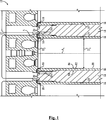
Bezug nehmend auf die 2 sind bestimmte Einzelheiten der Verbunddichtungsvorrichtung 20 detaillierter gezeigt. Die Verbunddichtungsvorrichtung 20 kann einen einteiligen Dichtungskörper 22 umfassen, der einen Außenumfang 24 und einen eine Zylinderöffnung 28 mit einer Mittelachse A2 definierenden Innenumfang 26 umfasst. Der Dichtungskörper 22 kann weiterhin eine Oberseite 30 umfassen, die sich in einer radialen Richtung zwischen dem Innenumfang 26 und dem Außenumfang 24 erstreckt, d. h., in einer Richtung normal zu einer Ausrichtung der Achse A2. Der Dichtungskörper 22 kann weiterhin eine der Oberseite 30 gegenüber angeordnete Unterseite (in der 2 nicht sichtbar) und einen äußeren Radialbereich 34 aufweisen, der mehrere Öffnungen 36 enthält, die eine Verbindung zwischen der Oberseite 30 und der Unterseite herstellen. Der Dichtungskörper 22 kann weiterhin einen inneren Radialbereich 38 umfassen, der eine Verbrennungsdichtung 40 mit einer Motorkopfdichtfläche 42 und einer Zylinderlaufbuchsendichtfläche (in der 2 nicht sichtbar) aufweist.Referring to the 2 are certain details of the composite sealing device 20 shown in more detail. The composite sealing device 20 can be a one-piece seal body 22 include an outer circumference 24 and a cylinder opening 28 with a central axis A 2 defining inner circumference 26 includes. The seal body 22 can still have a top 30 include, extending in a radial direction between the inner circumference 26 and the outer circumference 24 extends, that is, in a direction normal to an orientation of the axis A 2 . The seal body 22 can continue one of the top 30 opposite arranged bottom (in the 2 not visible) and an outer radial area 34 have several openings 36 that contains a connection between the top 30 and the bottom. The seal body 22 can still have an inner radial area 38 include a combustion seal 40 with an engine head sealing surface 42 and a cylinder liner sealing surface (in the 2 not visible).
Bezug nehmend auf die 3 ist der Dichtungskörper 22 in einer relativ zu der Ansicht der 2 umgedrehten Ansicht gezeigt und stellt außerdem Bereiche des Motorkopfes 12 und eines Schraubbolzensatzes 112 dar, um den Dichtungskörpers 22 zwischen dem Motorkopf 12 und dem Motorgehäuse 14 zu klemmen. Das Motorgehäuse 14 ist in der 3 nicht gezeigt, wobei die Unterseite 32 und die Zylinderlaufbuchsendichtfläche 43 sichtbar sind. In der 3 ist ebenfalls eine in der Unterseite 32 gebildete Ausnehmung 44 gezeigt, z. B. durch maschinelles Bearbeiten, die in radialer Richtung gesehen zu der Zylinderlaufbuchsendichtfläche 43 außen liegt. Die Ausnehmung 44 ist dazu ausgebildet, darin einen schützenden Endvorsprung einer Zylinderlaufbuchse, wie z. B. einer der Zylinderlaufbuchsen 16, wie weiterhin hierin beschrieben aufzunehmen. Die Zylinderöffnung 28 kann eine Kreisform aufweisen und die Ausnehmung 44 kann in einer Ausführungsform eine durchgehende ringförmige Ausnehmung sein, die die Mittelachse A2 umgibt und an die Zylinderlaufbuchsendichtfläche 43 angrenzt. In anderen Ausführungsformen könnte die Ausnehmung 44 nicht durchgehend sein und könnte z. B. mehrere in die Unterseite 32 eingeformten Ausnehmungen umfassen, die dazu ausgebildet sind, mehrere schützende Endvorsprünge einer Zylinderlaufbuchse aufzunehmen. Der Ausdruck „angrenzend” sollte hierin so verstanden werden, dass sich ein gegebenes Bauteil oder Merkmal direkt neben dem anderen Bauteil oder Merkmal des Interesses befindet. Im Gegensatz dazu bedeutet der Ausdruck „benachbart”, dass sich ein Bauteil oder Merkmal eines gegebenen Typs am nächsten befindliche Bauteil oder Merkmal des gegebenen Typs zu einem anderen Bauteil oder Merkmal des Interesses ist.Referring to the 3 is the seal body 22 in a relative to the view of 2 also shown areas of the engine head 12 and a bolt set 112 to the seal body 22 between the engine head 12 and the motor housing 14 to pinch. The motor housing 14 is in the 3 not shown, with the bottom 32 and the cylinder journal sealing surface 43 are visible. In the 3 is also one in the bottom 32 formed recess 44 shown, for. B. by machining, viewed in the radial direction to the cylinder liner sealing surface 43 lies outside. The recess 44 is adapted to therein a protective end projection of a cylinder liner, such. B. one of the cylinder liners 16 as further described herein. The cylinder opening 28 may have a circular shape and the recess 44 may in one embodiment be a continuous annular recess surrounding the central axis A 2 and to the cylinder liner sealing surface 43 borders. In other embodiments, the recess could 44 not be consistent and could z. B. several in the bottom 32 molded recesses adapted to receive a plurality of protective end projections of a cylinder liner. The term "contiguous" should be understood herein to mean that a given component or feature is directly adjacent to the other component or feature of interest. In contrast, the term "adjacent" means that a component or feature of a given type is the closest component or feature of the given type to another component or feature of interest.
Wie oben erwähnt, können sich mehrere Öffnungen 36 in einem äußeren Radialbereich 34 befinden. In einer Ausführungsform können die Öffnungen 36 einen Satz von Schraubbolzenöffnungen 46, die in einem ersten Radialmuster um die Achse A2 angeordnet sind, und einen Satz von Fluiddurchlassöffnungen 48 umfassen, die in einem zweiten Radialmuster um die Achse A2 angeordnet sind, welches von dem ersten Radialmuster verschieden ist. Mehrere Fluiddurchlassdichtungen 50 können sich ebenfalls in dem äußeren Radialbereich 34 befinden und können jeweils mit eine einer der Fluiddurchlassöffnungen 48 zugeordnet sein. Wenn der Motorkopf 12 mit dem Motorgehäuse 14 verbunden ist kann der Dichtungskörper 22 dementsprechend Durchgänge, die sich zwischen dem Motorkopf 12 und dem Motorgehäuse 14 erstrecken, über die Fluiddurchlassdichtung 50 über eine Druckklemmlast zwischen dem Motorkopf 12 und dem Motorgehäuse 14 fluidabdichten. Eine ähnliche Herangehensweise zum Abdichten ist, wie weiterhin hierin beschrieben, mit Bezug auf die Verbrennungsdichtung 40 angewandt.As mentioned above, there may be several openings 36 in an outer radial area 34 are located. In one embodiment, the openings 36 a set of bolt holes 46 which are arranged in a first radial pattern about the axis A 2 , and a set of fluid passage openings 48 which are arranged in a second radial pattern about the axis A 2 , which is different from the first radial pattern. Multiple fluid passage seals 50 may also be in the outer radial area 34 can and are each with one of the fluid ports 48 be assigned. When the engine head 12 with the motor housing 14 is connected, the seal body 22 accordingly, passages extending between the engine head 12 and the motor housing 14 extend over the fluid passage seal 50 via a pressure clamping load between the motor head 12 and the motor housing 14 fluidabdichten. A similar approach to sealing, as further described herein, is with respect to the combustion seal 40 applied.
Für den Fachmann ist es leicht offensichtlich, dass das Design des Dichtungskörpers 22 auch zum Verwenden mit einem einzelnen Zylinder 19 in einem Motor 10 geeignet ist. Mit anderen Worten, anstatt einer Dichtungsvorrichtung wie z. B. bestimmte herkömmliche Dichtungskörper, die dazu ausgebildet sind, Dichtungen mit mehreren Motorzylindern bereitzustellen, ist der Dichtungskörper 22 einer von mehreren separaten Verbunddichtungsvorrichtungen, die jeweils mit einem Zylinder in einem Motor mit mehreren Zylindern verwendet werden können. Zu diesem Zweck kann der Dichtungskörper 22 eine einzigartige Konfiguration aufweisen, um mehrere Fluiddichtungen, die mit einem gegebenen Motorzylinder verbunden sind, bereitzustellen. Der Außenumfang 24 kann ein nicht einheitlicher Außenumfang sein, der einen eine ersten Nebennase 54 des äußeren Radialbereichs 34 definierenden ersten Umfangsabschnitt 52 und einen eine zweiten Nebennase 58 des äußeren Radialbereichs 34 definierenden zweiten Umfangsabschnitt 56 umfasst. Der Außenumfang 24 kann weiterhin einen dritten Umfangsabschnitt 60 aufweisen, der sich zwischen dem ersten Umfangsabschnitt 52 und dem zweiten Umfangsabschnitt 56 befindet und der eine erste Hauptnase 62 des äußeren Radialbereichs 34 definiert. Der Außenumfang 24 kann weiterhin einen vierten Umfangsabschnitt 64 enthalten, der sich ebenfalls zwischen dem ersten Umfangsabschnitt 52 und dem zweiten Umfangsabschnitt 56 und gegenüberliegend des dritten Umfangsabschnitts 60 befindet, der eine zweite Hauptnase 66 des äußeren Radialbereichs 34 definiert. Die Hauptnasen 62 und 66 können größer als die Nebennasen 54 und 58 sein.It will be readily apparent to those skilled in the art that the design of the seal body 22 also for use with a single cylinder 19 in an engine 10 suitable is. In other words, instead of a sealing device such. For example, certain conventional seal bodies that are configured to provide seals with multiple engine cylinders is the seal body 22 one of several separate composite seal devices, each of which may be used with a cylinder in a multi-cylinder engine. For this purpose, the sealing body 22 have a unique configuration to provide multiple fluid seals associated with a given engine cylinder. The outer circumference 24 may be a non-uniform outer perimeter, one a first minor nose 54 the outer radial area 34 defining the first peripheral portion 52 and a second secondary nose 58 the outer radial area 34 defining the second peripheral portion 56 includes. The outer circumference 24 may further include a third peripheral portion 60 having, extending between the first peripheral portion 52 and the second peripheral portion 56 located and the first main nose 62 the outer radial area 34 Are defined. The outer circumference 24 can continue a fourth peripheral portion 64 included, which is also between the first peripheral portion 52 and the second peripheral portion 56 and opposite to the third peripheral portion 60 There is a second main nose 66 the outer radial area 34 Are defined. The main noses 62 and 66 can be bigger than the noses 54 and 58 be.
Eine erste Anzahl von Schraubbolzenöffnungen 46 kann sich in einer ersten Hauptnase 62 befinden, wohingegen eine zweite, der ersten Anzahl gleiche, Anzahl von Schraubbolzenöffnungen 46 in der zweiten Hauptnase 66 befinden. Die Fluiddurchlassöffnungen 48 können sich in der ersten Hauptnase 62 und auch in der zweiten Hauptnase 66 befinden. Eine Anzahl von Fluiddurchlassöffnungen 48, die sich in den jeweiligen Nasen 62 und 66 befinden, kann verschieden sein. In den gezeigten Ausführungsformen sind fünf Fluiddurchlassöffnungen 48 in der ersten Hauptnase 62 angeordnet, wohingegen drei Fluiddurchlassöffnungen 48 in der zweiten Hauptnase 66 angeordnet sind. Es können sich drei der Schraubbolzenöffnungen 46 in der ersten Hauptnase 62 befinden, wohingegen sich drei der Schraubbolzenöffnungen 46 ebenfalls in der zweiten Hauptnase 66 befinden können. Die sich in der ersten Hauptnase 62 befindlichen Schraubbolzenöffnungen 46 können einen ersten Kreisbogen C1 definieren, der koaxial zu der Zylinderöffnung 28 angeordnet ist, wohingegen die sich in der zweiten Hauptnase 66 befindlichen Schraubbolzenöffnungen 46 einen zweiten Kreisbogen C2 desgleichen Kreises definieren können. Der erste Bogen C1 kann einen ersten Mittelpunkt M1 aufweisen, der zweite Bogen C2 kann einen zweiten Mittelpunkt M2 aufweisen und ein Linienabschnitt, der durch den ersten Mittelpunkt M1 und den zweiten Mittelpunkt M2 definiert ist, kann die Mittelachse A2 der Zylinderöffnung 28 schneiden. Jedoch werden andere Konfigurationen in Betracht gezogen, bei denen die Schraubbolzenöffnungen 46 relativ geringer symmetrisch um die Achse A2 angeordnet sind, wobei die in den dargestellten Figuren und hierin beschriebenen relativen Symmetrien zum Bereitstellen einer praktischen Anwendungsherangehensweise in Betracht gezogen sind.A first number of bolt holes 46 can be in a first main nose 62 whereas there are a second, the same number of, same number of bolt holes 46 in the second main nose 66 are located. The fluid passage openings 48 can be in the first main nose 62 and also in the second main nose 66 are located. A number of fluid ports 48 that are in the respective noses 62 and 66 can be different. In the embodiments shown, there are five fluid passage openings 48 in the first main nose 62 arranged, whereas three fluid passage openings 48 in the second main nose 66 are arranged. There may be three of the bolt holes 46 in the first main nose 62 whereas there are three of the bolt holes 46 also in the second main nose 66 can be located. The ones in the first main nose 62 located bolt holes 46 may define a first arc C 1 coaxial with the cylinder opening 28 is arranged, whereas in the second main nose 66 located bolt holes 46 may define a second arc C 2 of the same circle. The first arc C 1 may have a first center M 1 , the second arc C 2 may have a second center M 2 , and a line segment defined by the first center M 1 and the second center M 2 may be the center axis A 2 the cylinder opening 28 to cut. However, other configurations are contemplated in which the bolt holes 46 are arranged relatively small symmetrically about the axis A 2 , taking into account the relative symmetries described in the figures and herein described to provide a practical application approach.
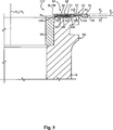
Ebenfalls unter Bezugnahme auf die 5 ist ein Bereich einer Zylinderlaufbuchse und einer Verbunddichtungsanordnung 110 für einen Verbrennungsmotor, wie z. B. dem Verbrennungsmotor 110, gezeigt, die bestimmten Bauteile detaillierter zeigen und annähernd dem Bereich der 1 entsprechen, der mit einem gestrichelten Kreis 5 dargestellt ist. Gleiche Bezugszeichen sind dazu verwendet, gleiche Merkmale zu kennzeichnen, die wie hierin beschrieben in Verbindung mit den anderen Zeichnungen verwendet worden sind. Wie oben bereits diskutiert wurde, kann die Verbrennungsdichtung 40 die Motorkopfdichtfläche 42 und die Zylinderlaufbuchsendichtfläche 43 enthalten. Die Zylinderlaufbuchsendichtfläche 43 kann einen Teil der Unterseite 32 bilden und die Ausnehmung 44 kann in die Unterseite 42 eingeformt sein und in radialer Richtung gesehen zu der Zylinderlaufbuchsendichtfläche 43 außen liegen. Wie ebenfalls oben diskutiert wurde, ist die Ausnehmung 44 dazu ausgebildet, darin einen schützenden Endvorsprung einer Zylinderlaufbuchse aufzunehmen. In der 5 ist ein schützender Endvorsprung 102 einer Zylinderlaufbuchse 16 gezeigt, der in der Ausnehmung 44 aufgenommen ist. Die Zylinderlaufbuchsendichtfläche 43 kann eine ebene Fläche sein, die eine erste Dichtebene P1 definiert, und die Motorkopfdichtfläche 42 kann ebenfalls eine ebene Dichtfläche sein, die eine zweite Dichtebene P2 parallel zu der ersten Dichtebene P1 definiert. Die Zylinderlaufbuchsendichtfläche 43 und die Motorkopfdichtfläche 42 können sich jeweils benachbart dem Innenumfang 26 an überlappenden Radialpositionen relativ zu der Mittelachse A2 befinden. In einer Ausführungsform können die Zylinderlaufbuchsendichtfläche 43 und die Motorkopfdichtfläche 42 identische Radialpositionen relativ zu der Mittelachse A2 aufweisen. Mit anderen Worten kann sich die Zylinderlaufbuchsendichtfläche 43 in einem radialen Abstand normal zur Achse A2 erstrecken, welcher gleich einem radialen Abstand ist, mit dem sich die Motorkopfdichtfläche 42 normal zur Achse A2 erstreckt. In anderen Ausführungsformen könnten nicht überlappende oder radial beabstandete Dichtflächen verwendet werden.Also with reference to the 5 is an area of a cylinder liner and a composite gasket assembly 110 for an internal combustion engine, such. B. the internal combustion engine 110 , shown in more detail the specific components and approximately the range of 1 match that with a dashed circle 5 is shown. Like reference numerals are used to identify similar features as used herein in conjunction with the other drawings. As discussed above, the combustion seal can 40 the engine head sealing surface 42 and the cylinder journal sealing surface 43 contain. The cylinder block sealing surface 43 can be part of the bottom 32 form and the recess 44 can in the bottom 42 be formed and seen in the radial direction to the cylinder liner sealing surface 43 lie outside. As also discussed above, the recess is 44 adapted to receive therein a protective end projection of a cylinder liner. In the 5 is a protective end tab 102 a cylinder liner 16 shown in the recess 44 is included. The cylinder block sealing surface 43 may be a flat surface defining a first sealing plane P 1 and the engine head sealing surface 42 may also be a flat sealing surface defining a second sealing plane P 2 parallel to the first sealing plane P 1 . The cylinder block sealing surface 43 and the engine head sealing surface 42 can each be adjacent to the inner circumference 26 at overlapping radial positions relative to the central axis A 2 . In an embodiment, the cylinder liner sealing surface 43 and the engine head sealing surface 42 have identical radial positions relative to the central axis A 2 . In other words, the cylinder liner sealing surface may 43 extend at a radial distance normal to the axis A 2 , which is equal to a radial distance with which the engine head sealing surface 42 extends normal to the axis A 2 . In other embodiments, non-overlapping or radially spaced sealing surfaces could be used.
Die Verbrennungsdichtung 40 kann eine mehrschichtige Verbrennungsdichtung sein, die mehrere Materialschichten zwischen der Zylinderlaufbuchsendichtfläche 43 und der Motorkopfdichtfläche 43 enthält. Insbesondere kann die Verbrennungsdichtung 40 eine erste Metallplatte 68, die die Zylinderlaufbuchsendichtfläche 43 enthält, eine zweite Metallplatte 70, die die Motorkopfdichtfläche 42 enthält, und eine dritte Metallplatte 72, die sich zwischen der ersten Metallplatte 68 und der zweiten Metallplatte 70 befindet, umfassen. In einer Ausführungsform können die erste und zweite Metallplatte 68 und 70 verschiedene Bereiche von einer einzigen Metallplatte sein, die um die dritte Metallschicht 72 gefaltet ist. Die dritte Metallplatte 72 kann eine Metallfederplatte sein, die einen ebenen, belasteten Zustand und einen nicht ebenen, unbelasteten Zustand aufweist. In der 5 ist die Metallfederplatte 72 näherungsweise gezeigt, als könnte sie in einem unbelasteten Zustand erscheinen, in dem keine Dichtungslast auf die Verbrennungsdichtung 40 aufgebracht ist. Wenn eine Dichtungslast von ausreichender Größe aufgebracht wird, kann davon ausgegangen werden, dass sich die Metallfederplatte 72 von der in der 5 gezeigten Konfiguration verformen kann, um zu einer ebeneren Konfiguration zu gelangen. Der äußere Radialbereich 44 kann aus einem Material bestehen, das sich von dem Material der Verbrennungsdichtung 40 unterscheidet, oder der äußere Radialbereich 44 könnte aus einem durchgehenden Material sein, das dazu verwendet wird, eines oder beide der Platten 68 und 70 zu formen. Gemäß weiteren Ausführungsformen könnte die Verbrennungsdichtung 40 ein einheitliches Materialstück sein, an dem sich beide Flächen 72 und 43 befinden.The combustion seal 40 may be a multilayered combustion gasket having multiple layers of material between the cylinder liner sealing surface 43 and the engine head sealing surface 43 contains. In particular, the combustion seal 40 a first metal plate 68 that the cylinder journal sealing surface 43 contains a second metal plate 70 that the engine head sealing surface 42 contains, and a third metal plate 72 extending between the first metal plate 68 and the second metal plate 70 is included. In one embodiment, the first and second metal plates 68 and 70 different areas of a single metal plate being around the third metal layer 72 folded. The third metal plate 72 may be a metal spring plate having a flat, loaded state and a non-planar, unloaded state. In the 5 is the metal spring plate 72 approximately shown as if it could appear in an unloaded condition in which there is no sealing load on the combustion seal 40 is applied. If a sealing load of sufficient size is applied, it can be assumed that the metal spring plate 72 from in the 5 deformed configuration shown in order to achieve a more planar configuration. The outer radial area 44 can be from one Material consist of the material of the combustion seal 40 differs, or the outer radial area 44 could be made of a continuous material that is used to one or both of the plates 68 and 70 to shape. According to further embodiments, the combustion seal could 40 a uniform piece of material on which both surfaces 72 and 43 are located.
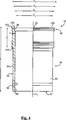
Bezug nehmend auf die 4 ist eine teilweise geschnittene und teilweise aufgeschnittene Ansicht einer Zylinderlaufbuchse 16 gemäß einer Ausführungsform gezeigt. Die Zylinderlaufbuchse 16 kann identisch zu anderen Zylinderlaufbuchsen sein, die in anderen Zeichnungen gezeigt und hierin beschrieben worden sind. Wie bereits diskutiert, kann die Zylinderlaufbuchse 16 einen Laufbuchsenkörper 80 enthalten, der eine Laufbuchsenwand 82 besitzt, die die Außenseite 84 und Innenseite 86 bildet. Der Laufbuchsenkörper 80 kann weiterhin ein erstes axiales Ende 92, ein zweites axiales Ende 94 mehrere axiale Abschnitte enthalten, die einen ersten axialen Abschnitt 96 bilden, der das erste axiale Ende 92 und die erste Längsbohrung 88 bildet. Mehrere axiale Abschnitte können weiterhin einen zweiten axialen Abschnitt 98 bilden, der das zweite axiale Ende 94 und die zweite Längsbohrung 90 bildet. Die zweite Längsbohrung 90 kann eine Manschettenringbohrung sein, die dazu ausgebildet ist, einen Manschettenring 18, wie in der 1 und 5 gezeigt, aufzunehmen. Der erste axiale Abschnitt 96 kann einen ersten Abschnittsdurchmesser D3 aufweisen, wohingegen der zweite axiale Abschnitt 98 einen zweiten Abschnittsdurchmesser D4 aufweisen kann, der größer als der erste Bereichsdurchmesser D3 ist. Die Durchmesser D3 und D4 weisen Abmessungen auf, die sich in einer Richtung normal zur Achse A2 zwischen breitesten Punkten der entsprechenden axialen Abschnitten 96 und 98 erstrecken und die Achse A2 schneiden.Referring to the 4 is a partially cut and partially cutaway view of a cylinder liner 16 according to one embodiment. The cylinder liner 16 may be identical to other cylinder liners shown in other drawings and described herein. As already discussed, the cylinder liner 16 a barrel body 80 containing a bushing wall 82 owns the outside 84 and inside 86 forms. The liner body 80 can also have a first axial end 92 , a second axial end 94 include a plurality of axial sections having a first axial section 96 form the first axial end 92 and the first longitudinal bore 88 forms. Multiple axial sections may further include a second axial section 98 form the second axial end 94 and the second longitudinal bore 90 forms. The second longitudinal bore 90 may be a sleeve ring bore, which is adapted to a sleeve ring 18 , like in the 1 and 5 shown to record. The first axial section 96 may have a first section diameter D 3 , whereas the second axial section 98 may have a second section diameter D 4 which is larger than the first section diameter D 3 . The diameters D 3 and D 4 have dimensions which are in a direction normal to the axis A 2 between widest points of the corresponding axial sections 96 and 98 extend and intersect the axis A 2 .
Das zweite axiale Ende 94 kann weiterhin eine Dichtfläche 100 aufweisen, die sich in einer radialen Richtung zwischen der Innenseite 86 und der Außenseite 84 erstreckt, und die dazu ausgebildet ist, mit der Zylinderlaufbuchsendichtfläche 43 der Verbrennungsdichtung 40 fluidabzudichten. Der schützende Endvorsprung 102 kann sich ebenfalls an dem zweiten axialen Ende 94 befinden und grenzt an die Dichtfläche 100 an. Der schützende Endvorsprung 102 ist wenigstens teilsweise dazu bereitgestellt, die Dichtfläche 100 vor Beschädigungen während der Handhabung und/oder dem Zusammenbau eines damit verbundenen Verbrennungsmotors, wie z. B. dem Motor 10, zu schützen. Der schützende Endvorsprung 102 kann in einer axialen Richtung von der Dichtfläche 100 hervorstehen und in bestimmten Ausführungsformen eine axiale Höhenabmessung parallel zur Achse A1 aufweisen, die weniger als ca. 1,0 Millimeter beträgt. Eine axiale Höhe des Endvorsprungs 102 kann ebenfalls weniger als ca. 0,75 Millimeter betragen. Wie hierin verwendet, kann „ca.” 1,0 Millimeter einen Wert zwischen 0,95 Millimeter und 1,04 Millimeter bedeuten, wohingegen „ca.” 0,75 Millimeter verstanden werden, dass hier ein Wert zwischen 0,70 und 0,79 Millimeter gemeint ist. Der schützende Endvorsprung 102 kann sich benachbart der Außenseite 84 befinden und kann relativ näher an der Außenseite 84 als an der Innenseite 86 angeordnet sein. Der erste axiale Abschnitt 96 kann eine Wanddicke t der Laufbuchsenwand 82 in einem Bereich zwischen der zweiten Bohrung 90 und einem Laufbuchsensitz 109 aufweisen, die gleich oder kleiner als ca. 12% des ersten Bohrungsdurchmessers D1 ist. Unter der Wandstärke t kann eine radiale Dicke zwischen der Innenseite 86 und der Außenseite 84 verstanden werden und kann ebenfalls gleich oder weniger als ca. 8% des ersten Bohrungsdurchmessers D1 in bestimmten Ausführungsformen betragen. Wie hierin verwendet, ist unter „ca.” 8% ein Wert zwischen 7,5% und 8,4% gemeint, und unter „ca.” 12% kann ein Wert zwischen 11,5% und 12,4% verstanden werden. Ähnliche Regelungen können verstanden werden, um auf andere numerische Maße oder Prozentwerten, wie hierin verwendet, geschlossen zu werden.The second axial end 94 can still have a sealing surface 100 have, extending in a radial direction between the inside 86 and the outside 84 extends, and which is configured with the cylinder liner sealing surface 43 the combustion seal 40 fluidabzudichten. The protective end projection 102 may also be at the second axial end 94 located and adjacent to the sealing surface 100 at. The protective end projection 102 is at least partially provided to the sealing surface 100 from damage during handling and / or assembly of an associated internal combustion engine, such. B. the engine 10 , to protect. The protective end projection 102 can be in an axial direction from the sealing surface 100 projecting and in certain embodiments have an axial height dimension parallel to the axis A 1 , which is less than about 1.0 millimeters. An axial height of the end projection 102 may also be less than about 0.75 millimeters. As used herein, "about" 1.0 millimeters may mean a value between 0.95 millimeters and 1.04 millimeters, whereas "about" 0.75 millimeters means that here is a value between 0.70 and 0, 79 millimeters is meant. The protective end projection 102 may be adjacent to the outside 84 can be located and relatively closer to the outside 84 as on the inside 86 be arranged. The first axial section 96 can have a wall thickness t of the bushing wall 82 in an area between the second hole 90 and a barrel seat 109 which is equal to or smaller than about 12% of the first bore diameter D 1 . Under the wall thickness t, a radial thickness between the inside 86 and the outside 84 can be understood and may also be equal to or less than about 8% of the first bore diameter D 1 in certain embodiments. As used herein, "about" 8% means a value between 7.5% and 8.4%, and "about" 12% may mean a value between 11.5% and 12.4%. Similar regulations may be understood to be to other numerical measures or percentages as used herein.
Ein Abstand von der Dichtfläche 100 zu dem Laufbuchsensitz 109 definiert eine Laufbuchsenflanschhöhe F, und ein Abstand von dem ersten axialen Ende 92 zu dem zweiten axialen Ende 94 definiert eine Laufhöhe L. In einer Ausführungsform kann die Laufbuchsenflanschhöhe F gleich oder kleiner als ca. 60% des ersten Bohrungsdurchmessers D1 sein, und die Laufbuchsenflanschhöhe F kann weiterhin gleich oder größer als ca. 30% der Laufbuchsenlänge L sein. Gemäß einer weiteren Ausführungsform kann der erste Bohrungsdurchmesser D1 gleich oder kleiner als ca. 150 Millimeter, die Wanddicke t kann gleich oder kleiner als ca. 12 Millimeter, die Laufbuchsenflanschhöhe F kann gleich oder kleiner als ca. 85 Millimeter und die Laufbuchsenlänge L kann gleich oder kleiner als ca. 300 Millimeter sein.A distance from the sealing surface 100 to the barrel seat 109 defines a bushing flange height F, and a distance from the first axial end 92 to the second axial end 94 defines a ride height L. In one embodiment, the liner flange height F may be equal to or less than about 60% of the first bore diameter D 1 , and the liner flange height F may be equal to or greater than about 30% of the liner length L. According to another embodiment, the first bore diameter D 1 may be equal to or less than about 150 millimeters, the wall thickness t may be equal to or less than about 12 millimeters, the bushing flange height F may be equal to or less than about 85 millimeters, and the bushing length L may be equal or less than about 300 millimeters.
Zurückkehrend zur 5 sind zusätzliche Merkmale der Laufbuchse 16 gezeigt. Wie bereits diskutiert kann die Ausnehmung 44 eine durchgehende ringförmige Ausnehmung sein, die koaxial mit der Zylinderöffnung 28 ist. Um Aufnahmen des Endvorsprungs 102 in der Ausnehmung 44 zu ermöglichen, kann der Endvorsprung 102 einen durchgehenden ringförmigen Vorsprung umfassen, der geeignete Abmessungen besitzt, so dass der Endvorsprung 102 leicht in die Ausnehmung 44 passt. Wenn eine Dichtungslast auf die Verbrennungsdichtung 40 aufgebracht wird, kann es gewünscht sein, eine Belastung des Endvorsprungs 102 zu vermeiden. Zu diesem Zweck kann eine axiale Höhe des Endvorsprungs 102 weniger als eine entsprechende axiale Tiefe der Ausnehmung 44 sein, so dass der Endvorsprung 102 den Dichtungskörper 22 in der Tat nicht berührt, wenn der Dichtungskörper 22 mit anderen Komponenten des Motors 10 zusammengebaut und zwischen dem Motorkopf 12 und der Zylinderlaufbuchse 16 geklemmt wird. In ähnlicher Weise kann eine radiale Breite des Endvorsprungs 102 in einer Richtung normal zu der Achse A1 zumindest in bestimmten Ausführungsformen kleiner als eine entsprechende radiale Breite der Ausnehmung 44 sein. Die Höhe/Länge und Breite des Endvorsprungs 102 kann relativ verglichen mit der entsprechenden Höhe/Länge und Breitenabmessungen der Zylinderlaufbuchse 16 klein sein. Der Endvorsprung 102 kann weiterhin an die Außenseite 84 der Zylinderlaufbuchse 16 angrenzen und kann koaxial mit der ersten und zweiten Längsbohrung 88 und 90 sein. Wie ebenfalls in der 5 gezeigt, ist eine Dichtebene, die durch die Dichtfläche 100 definiert ist, koplanar mit der Ebene D1 in der 5 und ist deshalb mit dem gleichen Bezugszeichen D1 beschrieben. Der Endvorsprung 102 kann weiterhin eine erste bearbeitete Kantenfläche 104 umfassen, die übergeht in und an die Außenseite 84 der Zylinderlaufbuchse 16 grenzt. Der Endvorsprung 102 kann weiterhin ebenfalls eine zweite bearbeitete Kantenfläche 106 umfassen, die übergeht in und an die Dichtfläche 100 grenzt, und eine bearbeitete Ebene der axialen Endfläche 108 umfassen, die sich von der ersten Kantenfläche 104 zu der zweiten Kantenfläche 106 erstreckt und eine weitere Ebene P3 parallel zu der Ebene P1 definiert. Die 5 beschreibt weiterhin komplementäre Querschnittsprofile der Zylinderlaufbuchse 16 und des Dichtungskörpers 22. Insbesondere kann das zweite axiale Ende 94 der Zylinderlaufbuchse 16 ein erstes Querschnittsprofil in einer Abschnittsebene aufweisen, die die Längsachse A1 der Zylinderlaufbuchse 16 enthält. Die Unterseite 32 des Dichtungskörpers 22 kann ein zweites Querschnittsprofil in einer Abschnittsebene umfassen, die die Mittelachse A2 der Zylinderöffnung 28 und einer zu dem ersten Querschnittsprofil komplementäre Form besitzt. Während berücksichtigt ist, dass die Verbunddichtungsvorrichtung 20 mit der Zylinderlaufbuchse 16 als Anordnung 110 in einer praktischen Anwendungsherangehensweise verwendet werden kann, sind die Komponenten nicht strikt darauf begrenzt, gemeinsam verwendet zu werden und in anderen Ausführungsformen könnte die Verbunddichtungsvorrichtung 20 mit verschiedenen Zylinderlaufbuchsen verwendet werden, und ähnliche Zylinderlaufbuchsen 16 könnten mit einer unterschiedlichen Dichtungsvorrichtung verwendet werden.Returning to 5 are additional features of the liner 16 shown. As already discussed, the recess 44 a continuous annular recess coaxial with the cylinder opening 28 is. To record the end projection 102 in the recess 44 to allow the end projection 102 a continuous annular projection having suitable dimensions, so that the end projection 102 slightly into the recess 44 fits. If a seal load on the combustion gasket 40 applied, it may be desired to load the end projection 102 to avoid. For this purpose, an axial height of the end projection 102 less than a corresponding axial depth of the recess 44 so that the end projection 102 the seal body 22 as a matter of fact not touched when the seal body 22 with other components of the engine 10 assembled and between the engine head 12 and the cylinder liner 16 is clamped. Similarly, a radial width of the end projection 102 in a direction normal to the axis A 1, at least in certain embodiments smaller than a corresponding radial width of the recess 44 be. The height / length and width of the end projection 102 can be relatively compared to the corresponding height / length and width dimensions of the cylinder liner 16 be small. The end projection 102 can continue to the outside 84 the cylinder liner 16 abut and coaxial with the first and second longitudinal bores 88 and 90 be. Like also in the 5 Shown is a sealing plane passing through the sealing surface 100 is defined, coplanar with the plane D 1 in the 5 and is therefore described by the same reference character D 1 . The end projection 102 can still have a first processed edge surface 104 that goes over and into the outside 84 the cylinder liner 16 borders. The end projection 102 can also continue a second machined edge surface 106 include, which merges into and on the sealing surface 100 borders, and a machined plane of the axial end face 108 include, extending from the first edge surface 104 to the second edge surface 106 extends and defines another plane P 3 parallel to the plane P 1 . The 5 further describes complementary cross-sectional profiles of the cylinder liner 16 and the seal body 22 , In particular, the second axial end 94 the cylinder liner 16 a first cross-sectional profile in a section plane having the longitudinal axis A 1 of the cylinder liner 16 contains. The bottom 32 of the seal body 22 may comprise a second cross-sectional profile in a section plane which is the central axis A 2 of the cylinder opening 28 and has a complementary shape to the first cross-sectional profile. While taking into account that the composite sealing device 20 with the cylinder liner 16 as an arrangement 110 can be used in a practical application approach, the components are not strictly limited to being used together, and in other embodiments, the composite sealing device could 20 be used with various cylinder liners, and similar cylinder liners 16 could be used with a different sealing device.
Gewerbliche AnwendbarkeitIndustrial Applicability
Unter allgemeiner Bezugnahme auf die Zeichnungen und insbesondere auf die 1 und 6, kann es im Laufe eines Motorbetriebslebens, oder während eines Wiederaufbauens, um den Motor auf einen erneuten Betrieb vorzubereiten, gewünscht sein, bestimmte Komponenten zu warten oder zu ersetzen. Unter diesen Komponenten können eine oder mehrere der Zylinderlaufbuchsen 16 und eine oder mehrere der Verbunddichtungsvorrichtungen 20 sein. Es ist ebenfalls bedacht, dass die Zylinderlaufbuchse 16 und die Verbunddichtungsvorrichtungen 20 bei der Herstellung von neuen Motoren oder beim Nachrüsten von existierenden Verbrennungsmotoren verwendet werden können. Wie bereits diskutiert, kann jede Verbunddichtungsvorrichtung 20 bei der Ausbildung von Fluiddichtungen, die einem einzelnen Zylinder 19/einer einzelnen Zylinderlaufbuchse 16 zugeordnet sind, verwendet werden. Die vorliegende Offenbarung ist folglich jedoch nicht darauf begrenzt und es Ausführungsformen sind berücksichtigt, die mehrere Verbrennungsdichtungen und eine relativ große Anzahl von Fluiddurchlassdichtungen in einem einzelnen Dichtungskörper zum Bereitstellen der notwendigen Fluiddichtheitsfunktionen für mehrere Zylinder besitzen. In ähnlicher Weise, während eine Motorkopfkonfiguration mit mehreren Einheiten wie hierin beschrieben verwendet werden kann, könnte in anderen Ausführungsformen eine einzelne Motorkopfeinheit verwendet werden. Die folgende Beschreibung sollte folglich derart verstanden werden, dass diese sich in ähnlicher Weise auf einen Zusammenbau von neuen Motoren, einem Wiederaufbau von existierenden Motoren mit neu oder wiederhergestellten Komponenten, Motoren mit separaten oder Verbundkopfeinheiten und Motoren mit individuell oder zusammengesetzten Verbunddichtungsvorrichtungen zu beziehen.With general reference to the drawings and in particular to the 1 and 6 For example, in the course of engine operating life, or during rebuilding to prepare the engine for reuse, it may be desirable to service or replace certain components. Among these components may be one or more of the cylinder liners 16 and one or more of the composite seal devices 20 be. It is also considered that the cylinder liner 16 and the composite sealing devices 20 can be used in the manufacture of new engines or in the retrofitting of existing internal combustion engines. As already discussed, any composite sealing device 20 in the formation of fluid seals, a single cylinder 19 / a single cylinder liner 16 are assigned to be used. However, the present disclosure is thus not limited thereto, and embodiments are contemplated that have multiple combustion seals and a relatively large number of fluid passage seals in a single seal body for providing the necessary multiple cylinder fluid tightness functions. Similarly, while a multi-unit engine head configuration may be used as described herein, in other embodiments a single engine head unit could be used. The following description should, therefore, be understood to similarly refer to an assembly of new engines, rebuilding existing or rebuilt engine components, separate or compound head engine engines, and individual or composite composite gasket engine engines.
Die Montage und Wartung des Motors 10 kann allgemein in herkömmlicher Weise durchgeführt werden. Jede der individuellen Kopfeinheiten des Motorkopfes 12 kann von dem Gehäuse 14 abmontiert werden und existierende Verbrennungsdichtungen und Kopfdichtungen können entfernt werden. Existierende Zylinderlaufbuchsen können entfernt und, wenn gewünscht, ersetzt werden. Es wird daran erinnert, dass die Zylinderlaufbuchsen nachgerüstete Zylinderlaufbuchsen sein können. Folglich könnte ein Entfernen von existierenden Zylinderlaufbuchsen ein Entfernen von Zylinderlaufbuchsen sein, die eine von den Zylinderlaufbuchsen 16 verschiedene Konfiguration aufweisen, die z. B. schützende Endvorsprünge aufweisen, die benachbart an einer Innenseite angeordnet sind, anstatt schützender Endvorsprünge, die sich benachbart an einer Außenseite befinden. In ähnlicher Weise können Verbunddichtungsvorrichtungen 20 nachgerüstete Dichtungsvorrichtungen sein. Folglich kann ein Entfernen von existierenden Dichtungsvorrichtungen ein Entfernen von Dichtungsvorrichtungen enthalten, die eine von den Verbunddichtungsvorrichtungen 20 verschiedene Konfiguration aufweisen. In früheren Systemen war es üblich, separate Komponenten für die Kopfdichtung gegen Verbrennungsdichtfunktionen einzusetzen.The assembly and maintenance of the engine 10 can generally be carried out in a conventional manner. Each of the individual head units of the engine head 12 can from the case 14 can be removed and existing combustion seals and head gaskets can be removed. Existing cylinder liners can be removed and replaced if desired. It is recalled that the cylinder liners can be retrofitted cylinder liners. Thus, removal of existing cylinder liners could be a removal of cylinder liners that are one of the cylinder liners 16 have different configuration, the z. B. have protective end projections which are disposed adjacent to an inner side, rather than protective end projections, which are adjacent to an outer side. Similarly, composite seal devices 20 be retrofitted sealing devices. Thus, removal of existing seal devices may include removal of seal devices that are one of the composite seal devices 20 have different configuration. In previous systems, it has been common to use separate components for the head gasket against combustion sealing functions.
Das Zusammenbauen eines Verbrennungsmotors 10, egal ob der Motor 10 neu oder in den Betrieb nach einem Wiederaufbau, einer Wartung, etc. zurückkehrt, kann ein in Kontakt Bringen einer Zylinderlaufbuchsendichtfläche 43 der Verbrennungsdichtung 40 mit der Dichtfläche 100 der Zylinderlaufbuchse 16 umfassen, wenn die Zylinderlaufbuchse 16 in dem Motorgehäuse 14 angeordnet ist. Das Zusammenbauen des Motors 10 kann weiterhin ein in Kontakt Bringen der Motorkopfdichtfläche 42 der Verbrennungsdichtung 40 mit dem Motorkopf 12 des Motors 10 umfassen. Während dem in Kontakt Bringen der Zylinderbuchsendichtfläche 43 mit der Zylinderlaufbuchse 16, kann der schützende Endvorsprung 112 in der Ausnehmung 44 aufgenommen werden. Wenn der Motorkopf 12, die Verbunddichtungsvorrichtung 20 und die Zylinderlaufbuchse 16 angemessen positioniert sind, kann eine Dichtungslast auf den Dichtungskörper 22 durch ein Klemmen des Dichtungskörpers 22 zwischen dem Motorgehäuse 14 und dem Motorkopf 12, wie weiter hierin beschrieben, aufgebracht werden. The assembling of an internal combustion engine 10 , no matter if the engine 10 new or returning to service after a rebuild, maintenance, etc. may be contacting a cylinder liner sealing surface 43 the combustion seal 40 with the sealing surface 100 the cylinder liner 16 include when the cylinder liner 16 in the motor housing 14 is arranged. Assembling the engine 10 may continue bringing the engine head sealing surface into contact 42 the combustion seal 40 with the engine head 12 of the motor 10 include. While contacting the cylinder box sealing surface 43 with the cylinder liner 16 , the protective end tab can 112 in the recess 44 be recorded. When the engine head 12 , the composite sealing device 20 and the cylinder liner 16 can be adequately positioned, a sealing load on the seal body 22 by clamping the sealing body 22 between the motor housing 14 and the engine head 12 as further described herein.
Die 6 zeigt einen Motor 10 in einem Zusammenbaustadium vor dem in Kontakt Bringen der Zylinderlaufbuchsendichtfläche 43 mit der Dichtfläche 100 der Zylinderlaufbuchse 16. Fachmänner werden mit der relativen Präzision, die bei dem Zusammenbau der verschiedenen Motorkomponenten gewünscht ist, vertraut sein, z. B. ist es typischerweise gewünscht, die Verbrennungsdichtung 14 koaxial mit der Zylinderlaufbuchse 16 anzuordnen. Es kann weiterhin gewünscht sein, die Verbrennungsdichtung 40 koaxial mit Bereichen des Motorkopfes 12 anzuordnen. Zu diesem Zweck können mehrere Führungsstiften 113 in das Motorgehäuse 14 eingepresst sein. Der Dichtungskörper 22 kann dann über eine Interaktion der Führungsstifte 113 mit Führungsstiftbohrungen 121 in den Dichtungskörper 22 zu einer Position gesteuert werden, bei der die Zylinderlaufbuchsendichtfläche 43 die Dichtfläche 100 der Zylinderlaufbuchse 16 kontaktiert. Der Dichtungskörper 22 kann gleichzeitig in einer Position ausgerichtet werden, bei der die Achse A2 mit der Achse A1 überlagert.The 6 shows a motor 10 at an assembly stage prior to contacting the cylinder block sealing surface 43 with the sealing surface 100 the cylinder liner 16 , Those skilled in the art will be familiar with the relative precision desired in assembling the various engine components, e.g. For example, it is typically desired to have the combustion gasket 14 coaxial with the cylinder liner 16 to arrange. It may also be desired, the combustion seal 40 coaxial with areas of the engine head 12 to arrange. For this purpose, multiple guide pins 113 in the motor housing 14 be pressed. The seal body 22 can then have an interaction of the guide pins 113 with guide pin holes 121 in the seal body 22 be controlled to a position where the cylinder block sealing surface 43 the sealing surface 100 the cylinder liner 16 contacted. The seal body 22 can be aligned simultaneously in a position in which the axis A 2 superimposed on the axis A 1 .
Der Motorkopf 12 kann dann über eine Interaktion der Führungsstifte 113 mit dem Führungsstiftbogen 123 in dem Motorkopf 12 in Kontakt mit dem Dichtungskörper 22 gebracht werden, so dass die Motorkopfdichtfläche 42 eine Unterseite 215 des Motorkopfes 12 kontaktiert. Der schützende Endvorsprung 102 kann während des Steuerns des Dichtungskörpers 22 in Kontakt mit der Zylinderlaufbuchse 16 in der Ausnehmung 44 positioniert werden. Bolzen 112 können dann durch den Motorkopf 12, den Dichtungskörper 22 und in die Bolzenöffnung 114 gelangen und in einer herkömmlichen Weise zum Klemmen des Dichtungskörpers 22, Motorkopfes 12 und Motorgehäuses 14 gesichert werden und die gewünschte Dichtungskraft aufbringen. Diese allgemeine Herangehensweise des Führens des Dichtungskörpers 22 über Führungsstiften 112 unterscheidet sich von früheren Techniken, die geeignet und speziell sind für eine zweiteilige Verbrennungsdichtung und Kopfdichtungssysteme, wo ein in der Zylinderlaufbuchse platzierter Manschettenring aus dem Motorgehäuse herausragte und die Verbrennungsdichtung führte.The engine head 12 can then have an interaction of the guide pins 113 with the guide pen bow 123 in the engine head 12 in contact with the sealing body 22 be brought so that the engine head sealing surface 42 a bottom 215 of the engine head 12 contacted. The protective end projection 102 can while controlling the seal body 22 in contact with the cylinder liner 16 in the recess 44 be positioned. bolt 112 can then go through the engine head 12 , the seal body 22 and in the bolt hole 114 arrive and in a conventional manner for clamping the seal body 22 , Engine head 12 and motor housing 14 be secured and apply the desired sealing force. This general approach of guiding the seal body 22 about guide pins 112 differs from earlier techniques that are suitable and specific to a two-part combustion gasket and head gasket systems where a sleeve ring placed in the cylinder liner protruded from the engine housing and carried the combustion gasket.
In bestimmten Beispielen kann es gewünscht sein, eine relativ große Dichtungslast auf den inneren Radialbereich 38 als auf den äußeren Radialbereich 34 aufzubringen. Ein Spitzendruck in dem entsprechenden Zylinder oder der Zylinderlaufbuchse 16 kann eine relativ dichtere, mehr robustere Verbrennungsdichtung erfordern als der benötigte für Fluiddurchlassdichtungen 50. Dementsprechend kann ein Aufbringen einer Dichtungslast ein Aufbringen einer relativ größeren Last auf den inneren Radialbereich 38 als auf den äußeren Radialbereich 34 über das Klemmen des Dichtungskörpers 22 zwischen dem Motorkopf 12 und dem Gehäuse 14 enthalten. Eine ungleiche Verteilung der Last zwischen dem inneren Radialbereich 38 und dem äußeren Radialbereich 34 kann z. B. über eine Bearbeitung des Maschinenkopfes 12 erreicht werden, so dass die Fläche 215 geringfügig näher an dem Motorgehäuse 14 in einem Bereich 16 der Fläche 215 ist, die den inneren Radialbereich 38 berührt, als an einem Bereich 218 der Fläche 215, die einen äußeren Radialabschnitt 34 berührt. Mit anderen Worten kann die Fläche 215 so bearbeitet werden, dass diese geringfügig uneben ist, um eine ungleiche Last auf die Bereiche 34 und 38 aufzubringen. Alternativ könnte eine axiale Dicke des Dichtungskörpers 22 so ausgebildet sein, dass der Dichtungskörper 22 relativ dicker in dem inneren radialen Bereich 38 als in dem äußeren radialen Bereich 34 ist, oder die Oberfläche 118 des Motorgehäuses 14 könnte so bearbeitet sein, um uneben zu sein. Weiterhin könnten die Schraubbolzenöffnungen 46, 114 und 214 so angeordnet sein, dass die Dichtungskraft relativ näher an oder in dem inneren Radialbereich 38 aufgebracht wird, die eine relativ größere Proportion der Last auf den inneren Radialbereich 38 als auf den äußeren Radialbereich 34 vermittelt.In certain examples, it may be desired to have a relatively large sealing load on the inner radial region 38 as on the outer radial area 34 applied. A peak pressure in the corresponding cylinder or cylinder liner 16 may require a relatively denser, more robust combustion seal than the one needed for fluid passage seals 50 , Accordingly, applying a sealing load may apply a relatively larger load to the inner radial region 38 as on the outer radial area 34 about the clamping of the seal body 22 between the engine head 12 and the housing 14 contain. An uneven distribution of the load between the inner radial area 38 and the outer radial region 34 can z. B. via a machining of the machine head 12 be achieved, so that the area 215 slightly closer to the motor housing 14 in one area 16 the area 215 is that the inner radial area 38 touches, as at an area 218 the area 215 that has an outer radial section 34 touched. In other words, the area can be 215 be edited so that it is slightly uneven to an unequal load on the areas 34 and 38 applied. Alternatively, an axial thickness of the seal body 22 be formed so that the sealing body 22 relatively thicker in the inner radial region 38 as in the outer radial region 34 is, or the surface 118 of the motor housing 14 could be edited to be uneven. Furthermore, the bolt bolt openings 46 . 114 and 214 be arranged so that the sealing force is relatively closer to or in the inner radial region 38 is applied, which is a relatively larger proportion of the load on the inner radial region 38 as on the outer radial area 34 taught.
In einigen Motoren kann die relativ hohe Dichtungskraft, die auf eine Verbrennungsdichtung über ein Verschrauben des Motorkopfes mit dem Motorgehäuse aufgebracht wird, dazu tendieren, eine Zylinderlaufbuchse zu verformen. Insbesondere kann sich eine Zylinderlaufbuchse in einer Richtung normal zu ihrer Mittelachse unter einer Schraublast, die zum Abdichten der Verbrennungsdichtung aufgebracht ist, nach außen hin aufwölben. Solch eine Verformung kann besonders problematisch in Anwesenheit von relativ hohen Verbrennungstemperaturen und Drücken sein, die die Zylinderlaufbuchse und die zugehörigen Komponenten erfahren. Während eine Verformung der Zylinderlaufbuchse typischerweise so klein sein wird, dass diese für das menschliche Auge unbemerkbar ist, kann dies in Dichtungsproblemen um einen Motorkolben resultieren, besonders wenn der Kolben den oberen Todpunkt in der Zylinderlaufbuchse erreicht. Insbesondere kann eine Verformung einen Spalt zwischen dem Manschettenring und dem Kolben dazu veranlassen, größer zu werden. In einigen Beispielen kann eine Verformung der Laufbuchse ebenfalls die Außenfläche des Manschettenrings dazu veranlassen, die Innenseite der Laufbuchse nicht länger zu dichten. Als Ergebnis dieses Phänomens können Verbrennungsgase aus dem Motorzylinder durch ein im Stand der Technik als „Leckgas” bekanntes Phänomen auftreten. Bestimmte frühere Herangehesweisen versuchten die Zylinderlaufbuchsenverformung durch ein Bilden der Zylinderlaufbuchsen mit relativ Dicken Laufbuchsenwänden zu begrenzen. Während sich diese Herangehensweise als relativ effektiv gezeigt hat, kann es in anderen Beispielen ungewünscht sein, relativ dicke Zylinderlaufbuchsen zu verwenden. Zum Beispiel können bestimmte Motoren dazu angepasst sein, nach einer Wartung von einem Dieselmotor als ein Gasmotor verwendet zu werden. Für Motorzylinder, die in Gasmotoren verwendet werden, ist es üblich, verschiedene Konfigurationen oder Abmessungen als bestimmte, vergleichbar dimensionierte Dieselmotoren zu besitzen. Dementsprechend kann die Verwendung einer relativ dünneren Zylinderlaufbuchsen gegenüber einer dickwandigeren Laufbuchse eine relativ große Menge von Motorgehäusematerial zum späteren Aufbohren eines Motorzylinders bewahren, um im späteren Betriebsleben eine Verwendung als Erdgasmotor zu ermöglichen.In some engines, the relatively high sealing force applied to a combustion seal via bolting of the engine head to the engine housing may tend to deform a cylinder liner. In particular, a cylinder liner may bulge outwardly in a direction normal to its central axis under a screw load applied to seal the combustion gasket. Such deformation can be particularly problematic in the presence of relatively high combustion temperatures and pressures experienced by the cylinder liner and associated components. While a deformation of the cylinder liner is typically so small will be unnoticeable to the human eye, this can result in sealing problems around an engine piston, especially when the piston reaches the top dead center in the cylinder liner. In particular, deformation may cause a gap between the sleeve ring and the piston to increase in size. In some examples, deformation of the bushing may also cause the outer surface of the boot ring to no longer seal the inside of the bushing. As a result of this phenomenon, combustion gases from the engine cylinder may occur due to a phenomenon known in the art as "leak gas." Certain prior approaches have attempted to limit cylinder liner deformation by forming the cylinder liners with relatively thick liner walls. While this approach has been found to be relatively effective, in other examples it may be undesirable to use relatively thick cylinder liners. For example, certain engines may be adapted to be used as a gas engine after servicing a diesel engine. For engine cylinders used in gas engines, it is common to have different configurations or dimensions than certain comparable sized diesel engines. Accordingly, the use of a relatively thinner cylinder liners over a thicker walled liner may preserve a relatively large amount of engine housing material for later drilling an engine cylinder to allow for later use as a natural gas engine.
Die vorliegende Offenbarung weicht ebenfalls von herkömmlichen, dickwandigen Laufbuchsenstrategien durch ein, unter anderem, Ausbilden von Zylinderlaufbuchsen und zugehörigen Dichtungsvorrichtungen in bestimmten Arten zum Begrenzen der Zylinderlaufbuchsenverformung ab, ohne dass ein Bedürfnis nach einer relativ langen Bohrung zum Aufnehmen einer relativ dickwandigen Zylinderlaufbuchse besteht. Diese Kombination von verschiedenen, hierin beschriebenen Merkmalen, wie z. B. der relativ dünnen Wand t der Zylinderlaufbuchse 16, der Länge der Laufbuchsenflanschhöhe F relativ zum Bohrungsdurchmesser D1, und der Länge L der Flanschhöhe relativ zur gesamten Laufbuchsenlänge, bilden alle zusammen eine Zylinderlaufbuchse, die einer geeigneten Dichtungslast ausgesetzt werden kann, ohne dass es zu Verformungen der Zylinderlaufbuchse und dem Austritt von Leckgasen von Verbrennungsgasen oder anderen Problemen kommt. Die vorliegende Offenbarung weicht ferner von bestimmten herkömmlichen Herangehensweisen derart ab, dass die Dichtungskraft, die auf die Verbrennungsdichtung 14 ausgeübt wird, einen Lastpfad zeigt, der mit einem Pfeil Z in der 6, der nahezu parallel zu der Achse A1 und zwischen der Innenseite 36 und der Außenseite 84 konzentriert verläuft, folgt. Durch Anordnen des schützenden Endvorsprungs 102 benachbart der Außenseite 84 anstatt der Innenseite 86, wie in bestimmten früheren Herangehensweisen, kann die Position der Verbrennungsdichtung 40 relativ nahe bei der Achse A1 ausgeführt werden. Als Ergebnis tendiert die Dichtungskraft dazu, durch die Zylinderlaufbuchse 16 über einen Lastpfad geleitet zu werden, der weniger dazu geeignet ist, äußere Wölbungen davon zu verursachen. Diese Eigenschaft ermöglicht es der Wanddicke t relativ dünn zu bleiben und kann eine Verwendung einer reduzierten Dichtungskraft in bestimmten Beispielen ermöglichen.The present disclosure also deviates from conventional thick-walled liner strategies by including, but not limited to, forming cylinder liners and associated sealing devices in certain ways to limit cylinder liner deformation without the need for a relatively long bore for receiving a relatively thick-walled cylinder liner. This combination of various features described herein, such as. B. the relatively thin wall t of the cylinder liner 16 , the length of the bushing flange height F relative to the bore diameter D 1 , and the length L of the flange height relative to the overall bushing length, all together form a cylinder liner which can be subjected to a suitable sealing load without causing cylinder liner deformations and leakages of leakage gases Combustion gases or other problems comes. The present disclosure further differs from certain conventional approaches in that the sealing force applied to the combustion gasket 14 is exercised, shows a load path with an arrow Z in the 6 which is almost parallel to the axis A 1 and between the inside 36 and the outside 84 concentrated, follows. By placing the protective end projection 102 adjacent to the outside 84 instead of the inside 86 As in certain previous approaches, the position of the combustion seal can be 40 be carried out relatively close to the axis A 1 . As a result, the sealing force tends to through the cylinder liner 16 to be routed through a load path that is less likely to cause external bulges thereof. This feature allows the wall thickness t to remain relatively thin and may allow use of a reduced sealing force in certain examples.
Ein weiteres Merkmal, das sich aus dem Platzieren der Verbrennungsdichtung 40 relativ nahe an der Achse A1 ergibt und somit den Innenumfang 26 näher an die Innenseite 86 des Laufbuchsenkörpers 80 bringt, ist eine Reduktion in dem „Spaltvolumen” verglichen mit früheren Bauformen, bei denen die Verbrennungsdichtung in radialer Richtung betrachtet zu dem schützenden Endvorsprung einer Zylinderlaufbuchse außen angeordnet war. Eine Reduktion des Spaltvolumens resultiert in weniger Platz in dem Zylinder, wo Kraftstoff- und Luftverbrennung dazu tendiert, unvollständig oder anderweitig unterschiedlich von einer gewünschten Weise aufzutreten.Another feature stemming from the placement of the combustion gasket 40 relatively close to the axis A 1 results and thus the inner circumference 26 closer to the inside 86 of the liner body 80 brings is a reduction in the "gap volume" compared to previous designs, in which the combustion seal was arranged in the radial direction to the protective end projection of a cylinder liner outside. A reduction in the gap volume results in less space in the cylinder where fuel and air combustion tends to occur incompletely or otherwise differently from a desired manner.
Die vorliegende Beschreibung dient nur für darstellende Zwecke und sollte nicht ausgelegt werden, den Umfang der vorliegenden Offenbarung in irgendeiner Weise einzuschränken. Folglich wird der Fachmann verstehen, dass verschiedene Modifikationen für die vorliegenden beschriebenen Ausführungsformen durchgeführt werden könnten, ohne vom gesamten und angemessenen Schutzbereich und Geist der vorliegenden Offenbarung abzuweichen. Andere Aspekte, Merkmale und Vorteile werden bei einer Prüfung der angehängten Zeichnungen und der beigefügten Ansprüche offensichtlich.The present description is for illustrative purposes only and should not be construed to limit the scope of the present disclosure in any way. Accordingly, it will be understood by those skilled in the art that various modifications could be made to the presently described embodiments without departing from the entire and appropriate scope and spirit of the present disclosure. Other aspects, features, and advantages will become apparent upon a review of the attached drawings and the appended claims.
ZITATE ENTHALTEN IN DER BESCHREIBUNG QUOTES INCLUDE IN THE DESCRIPTION
Diese Liste der vom Anmelder aufgeführten Dokumente wurde automatisiert erzeugt und ist ausschließlich zur besseren Information des Lesers aufgenommen. Die Liste ist nicht Bestandteil der deutschen Patent- bzw. Gebrauchsmusteranmeldung. Das DPMA übernimmt keinerlei Haftung für etwaige Fehler oder Auslassungen.This list of the documents listed by the applicant has been generated automatically and is included solely for the better information of the reader. The list is not part of the German patent or utility model application. The DPMA assumes no liability for any errors or omissions.
Zitierte PatentliteraturCited patent literature
-
US 4474147 [0003] US 4474147 [0003]