US4458491A - Supercharged reciprocating internal combustion engine - Google Patents
Supercharged reciprocating internal combustion engine Download PDFInfo
- Publication number
- US4458491A US4458491A US06/413,396 US41339682A US4458491A US 4458491 A US4458491 A US 4458491A US 41339682 A US41339682 A US 41339682A US 4458491 A US4458491 A US 4458491A
- Authority
- US
- United States
- Prior art keywords
- exhaust
- internal combustion
- combustion engine
- reciprocating internal
- exhaust manifold
- Prior art date
- Legal status (The legal status is an assumption and is not a legal conclusion. Google has not performed a legal analysis and makes no representation as to the accuracy of the status listed.)
- Expired - Fee Related
Links
Images

Classifications
-
- F—MECHANICAL ENGINEERING; LIGHTING; HEATING; WEAPONS; BLASTING
- F01—MACHINES OR ENGINES IN GENERAL; ENGINE PLANTS IN GENERAL; STEAM ENGINES
- F01N—GAS-FLOW SILENCERS OR EXHAUST APPARATUS FOR MACHINES OR ENGINES IN GENERAL; GAS-FLOW SILENCERS OR EXHAUST APPARATUS FOR INTERNAL-COMBUSTION ENGINES
- F01N13/00—Exhaust or silencing apparatus characterised by constructional features
- F01N13/08—Other arrangements or adaptations of exhaust conduits
- F01N13/10—Other arrangements or adaptations of exhaust conduits of exhaust manifolds
-
- F—MECHANICAL ENGINEERING; LIGHTING; HEATING; WEAPONS; BLASTING
- F02—COMBUSTION ENGINES; HOT-GAS OR COMBUSTION-PRODUCT ENGINE PLANTS
- F02B—INTERNAL-COMBUSTION PISTON ENGINES; COMBUSTION ENGINES IN GENERAL
- F02B37/00—Engines characterised by provision of pumps driven at least for part of the time by exhaust
- F02B37/02—Gas passages between engine outlet and pump drive, e.g. reservoirs
-
- Y—GENERAL TAGGING OF NEW TECHNOLOGICAL DEVELOPMENTS; GENERAL TAGGING OF CROSS-SECTIONAL TECHNOLOGIES SPANNING OVER SEVERAL SECTIONS OF THE IPC; TECHNICAL SUBJECTS COVERED BY FORMER USPC CROSS-REFERENCE ART COLLECTIONS [XRACs] AND DIGESTS
- Y02—TECHNOLOGIES OR APPLICATIONS FOR MITIGATION OR ADAPTATION AGAINST CLIMATE CHANGE
- Y02T—CLIMATE CHANGE MITIGATION TECHNOLOGIES RELATED TO TRANSPORTATION
- Y02T10/00—Road transport of goods or passengers
- Y02T10/10—Internal combustion engine [ICE] based vehicles
- Y02T10/12—Improving ICE efficiencies
Definitions
- the present invention relates to a reciprocating internal combustion engine and, more particularly, to a supercharged internal combustion engine, with the supercharging being effected by way of an exhaust gas turbocharger, and with the engine including two banks of cylinders mounted at an angle to one another, the cylinder heads being connected to the engine block along mounting surfaces, as well as an exhaust manifold system disposed between the cylinder banks, and with the arrangement providing for an operation of the turbine of the exhaust gas turbocharger in a ramming process, with exhaust gases from the manifold.
- Reciprocating internal combustion engines of the aforementioned type have been proposed wherein the exhaust manifold is disposed between banks of cylinder at a level or above cylinder heads.
- the exhaust manifold system is surrounded by an expensive jacket in order to reduce environmental pollution caused by radiation of heat and noise and also to maintain an energy content of the exhaust gases.
- an ambient temperature corresponds to the temperature of the engine compartment so that there is a high effective temperature differential with respect to the exhaust gas temperature and, consequently, a considerable thickness of material is required to ensure the proper amount of heat insulation.
- the aim underlying the present invention essentially resides in providing an arrangement for exhaust manifold system in a supercharged reciprocating internal combustion engine, which arrangement eliminates if not substantially reduces undesired pollution of the environment by radiated heat and noise.
- an exhaust manifold which is common to all cylinders, with a turbine of at least one exhaust gas turbocharger being supplied from the common exhaust manifold.
- the exhaust manifold is disposed inside the engine block in a tunnel-shaped chamber, which chamber is delimited by longitudinally extending walls of the engine block.
- the walls are linked together at an angle between the banks of the cylinder and by a sealing wall, with the wall linking or connecting the longitudinally extending walls together at a level of mounting surfaces on the two banks of the cylinders.
- the undesireable pollution of the environment due to radiated heat and noise from the exhaust manifold system is optimally reduced due to the encapsulation within the engine block.
- the ambient temperature of the tunnel shaped chamber corresponds to operating temperatures of the reciprocating internal combustion engine so that the temperature differential with respect to the exhaust gas is less than when the exhaust manifold is located outside of the engine block.
- the energy loss from the exhaust gases on the way from the cylinder to the turbine of the exhaust gas turbocharger is reduced by virtue of the present invention so that the effectiveness of the supercharging is improved by the exhaust gas which is richer or higher in energy.
- a cross section of the tunnel-shaped chamber, not completely filled by the exhaust manifold advantageously serves as an exhaust manifold for the turbine exhaust.
- the exhaust manifold may be surrounded by the jacket tube with a space provided between the exhaust manifold and the jacket tube.
- an outlet of the turbine of the at least one exhaust gas turbocharger terminates in an intermediate chamber between the exhaust manifold and the jacket tube.
- an inlet of the tubine of at least one additional exhaust gas turbocharger is connected to the intermediate chamber defined between the exhaust manifold and jacket tube.
- An inlet stub of an exhaust system may, in accordance with the present invention, be connected to the tunnel-shaped chamber. It is also possible for the inlet stub of the exhaust system to be connected to the intermediate chamber defined between the exhaust manifold and jacket tube.
- the exhaust manifold is surrounded with a heat insulating material and, likewise, the jacket tube may also be surrounded with a heat insulating material.
- Insertable tubes may, in accordance with the present invention, be disposed as an exhaust guiding connection to the exhaust manifold as well as to the intermediate space defined between the jacket tube and exhaust manifold.
- Mounting openings may be provided and disposed in a sealing wall, with the mounting openings being closable by liquid-cooled lids or covers.
- the mounting openings, closable by lids or covers may be disposed on the engine block at endwise walls of the tunnel-shaped chamber.
- Another object of the present invention resides in providing a supercharged reciprocating internal combustion engine which minimizes if not avoids the undesireable pollution of the environment by radiated heat and/or noise from the exhaust manifold system,
- Another object of the present invention resides in providing a supercharged reciprocating internal combustion engine which improves the overall effectiveness of the supercharging during all operating loads of the engine.
- a still further object of the present invention resides in providing a supercharged internal combustion engine which reduces the temperature differential between an engine compartment accommodating the engine and the exhaust gases.
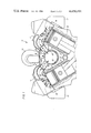
- FIG. 1 is a partial cross sectional view of a supercharged reciprocating internal combustion engine constructed in accordance with the present invention having a single-walled exhaust manifold.
- FIG. 2 is a partial cross sectional view of a supercharged reciprocating internal combustion engine constructed in accordance with the present invention, with a double-walled exhaust manifold;
- FIG. 3 is a partial cross sectional view of a supercharged reciprocating internal combustion engine constructed in accordance with the present invention, with two-staged supercharging and a double-walled exhaust manifold.
- a reciprocating internal combustion engine generally designated by the reference numeral 11 is applied with precompressed boost air for supercharging by at least one exhaust gas turbocharger 12 or, as shown in FIG. 3, by a further exhaust gas turbocharger 13.
- the boost air flows through boost air or supercharging air lines 17 to respective cylinders of the engine 11, with the cylinders being disposed in two rows or banks at an angle with respect to one another.
- An individual cylinder head is associated with each cylinder or bank of cylinders and is connected or secured to an engine block at a mounting surface 16 provided on the block 15.
- the respective cylinder heads 14 are provided with exhaust outlet or discharge channels 18 which communicate with an opening 19 provided in the mounting surface 16 of the engine block 15.
- An exhaust manifold system is provided which includes an exhaust manifold 20 which is common to all of the cylinders of the engine 11.
- the exhaust manifold system is disposed between the banks of cylinders, within an engine block 15, in a tunnel-shaped chamber 21 and is connected by insertable tubes 22 with the exhaust outlet or discharge channels 18.
- the tunnel-like space 21 is delimited by longitudinally extending walls 23 of the engine block 15 and by a sealing wall 24, with the longitudinally extending walls 23 being connected together at the angle between the banks of the cylinders, and with the sealing wall 24 connecting the longitudinally extending walls 23 at a level of the mounting surfaces 16 of the rows or banks of cylinders.
- the exhaust gas turbocharger 12 is supplied with hot exhaust gases from an insertable connection member 26 from the exhaust gas manifold 20.
- the exhaust gas manifold 20 may be protected by a layer of heat insulation 25.
- the exhaust gas, which expands in the turbine of the exhaust gas turbocharger 12, is blown or directed out into the cross section of the tunnel-shaped chamber 21, which chamber 21 is not completely filled by the exhaust gas manifold 20.
- a muffler assembly (not shown) of the reciprocating internal combustion engine 11 together with its accommpanying noise reducing elements (not shown) is connected to the tunnel-shaped chamber 21 which serves as an exhaust manifold.
- the exhaust manifold 21 may be surrounded by a jacket-shaped tube 27 with the tube 27 being spaced from an exterior surface of the exhaust manifold 21 by a plurality of supports 28 provided in the space 29 between the exhaust manifold 20 and jacket tube 27.
- the stream of exhaust gas is supplied or runs from the cylinder to an entrance of the turbine of the exhaust gas turbocharger 12 in the manner described hereinabove in connection with FIG. 1.
- the expanded exhaust gas is blown or driven out into the intermediate space 29 through a plug-in or insertable tube 31.
- the exhaust system (not shown) is connected to the intermediate space 29 so that the cross section of the tunnel shaped chamber 21 which is not completely filled by the exhaust manifold system remains free of exhaust gas.
- the jacket tube 27 may be protected along an exterior thereof by an appropriate layer of heat insulation material.
- the exhaust gas which is partially expanded in the exhaust gas turbocharger 12 cannot enter the exhaust system from the intermediate chamber 29, but rather enters through plug-in tube 30 into the low pressure turbine of the exhaust gas turbocharger 13 and is then blown out or directed into the cross-section of the tunnel-shaped chamber 21 which is not completely filled by the exhaust manifold system.
- the exhaust system (not shown) is connected to the tunnel-shaped chamber 21.
- the tunnel-like chamber 21 is provided on its end walls with mounting openings adapted to be closed by lids or covers for enabling an installation of the exhaust manifold 20 or the exhaust manifold 20 combined with the jacket tube 27.
- mounting openings are provided in closing wall 24 with the openings being closable by lids or covers, which lids or covers may be cooled by, for example, a liquid.
Landscapes
- Engineering & Computer Science (AREA)
- Chemical & Material Sciences (AREA)
- Combustion & Propulsion (AREA)
- Mechanical Engineering (AREA)
- General Engineering & Computer Science (AREA)
- Supercharger (AREA)
- Exhaust Silencers (AREA)
Applications Claiming Priority (2)
| Application Number | Priority Date | Filing Date | Title |
|---|---|---|---|
| DE3150001 | 1981-12-17 | ||
| DE3150001A DE3150001C2 (de) | 1981-12-17 | 1981-12-17 | Kolbenbrennkraftmaschine mit Aufladung |
Publications (1)
| Publication Number | Publication Date |
|---|---|
| US4458491A true US4458491A (en) | 1984-07-10 |
Family
ID=6148984
Family Applications (1)
| Application Number | Title | Priority Date | Filing Date |
|---|---|---|---|
| US06/413,396 Expired - Fee Related US4458491A (en) | 1981-12-17 | 1982-08-31 | Supercharged reciprocating internal combustion engine |
Country Status (8)
| Country | Link |
|---|---|
| US (1) | US4458491A (it) |
| JP (1) | JPS6029816B2 (it) |
| CH (1) | CH658297A5 (it) |
| DE (1) | DE3150001C2 (it) |
| ES (1) | ES8305464A1 (it) |
| FR (1) | FR2518645B1 (it) |
| GB (1) | GB2111123B (it) |
| IT (1) | IT1148389B (it) |
Cited By (17)
| Publication number | Priority date | Publication date | Assignee | Title |
|---|---|---|---|---|
| US4807436A (en) * | 1986-09-13 | 1989-02-28 | Mtu Motoren- Und Turbinen-Union Friedrichshafen Gmbh | Arrangement for the mounting of exhaust gas lines |
| US4951465A (en) * | 1988-07-01 | 1990-08-28 | Sanshin Kogyo Kabushiki Kaisha | Exhaust system for multi-cylinder engine |
| US5003934A (en) * | 1988-07-13 | 1991-04-02 | Mtu Friedrichshafen Gmbh | Hood covering the space between cylinder banks of an internal-combustion engine which are arranged in a V-shape |
| US5056310A (en) * | 1989-01-13 | 1991-10-15 | Mtu Motoren- Und Turbinen- Union Friedrichshafen Gmbh | Exhaust pipe for a multi-cylinder piston internal-combustion engine |
| US5440881A (en) * | 1990-06-02 | 1995-08-15 | Mtu Motor- Und Turbinen-Union Friedrichshafen | Intake system for an internal-combustion engine for use in one-stage or two-stage supercharging |
| US6176082B1 (en) | 1999-04-21 | 2001-01-23 | Caterpillar Inc. | Exhaust manifold cooling assembly for an internal combustion engine |
| US6305168B1 (en) * | 1999-03-18 | 2001-10-23 | Isuzu Motors Limited | V-type engine with turbocharger |
| GB2389147A (en) * | 2002-05-31 | 2003-12-03 | Man B & W Diesel Ltd | I.c. engine air manifold arrangement |
| US20060037592A1 (en) * | 2004-08-19 | 2006-02-23 | Perkins Engines Company Limited | Exhaust manifold arrangement |
| US20070056281A1 (en) * | 2005-09-13 | 2007-03-15 | Arvan Gary J | Integrated inboard exhaust manifolds for V-type engines |
| US20070107424A1 (en) * | 2005-11-17 | 2007-05-17 | Weber Technology Ag | V-engine having at least one turbocharger |
| US20080066465A1 (en) * | 2006-09-20 | 2008-03-20 | Francis Andrew Maidens | Turbocharger header for an internal combustion engine |
| US20100065003A1 (en) * | 2008-09-12 | 2010-03-18 | Ford Global Technologies, Llc | Induction system for internal combustion engine |
| US20110174247A1 (en) * | 2010-01-21 | 2011-07-21 | Ford Global Technologies, Llc | Central turbocharger mounting configuration for a twin-turbo engine |
| US20230399975A1 (en) * | 2022-06-13 | 2023-12-14 | Polaris Industries Inc. | Powertrain for a utility vehicle |
| US12187127B2 (en) | 2020-05-15 | 2025-01-07 | Polaris Industries Inc. | Off-road vehicle |
| US12384464B2 (en) | 2020-05-15 | 2025-08-12 | Polaris Industries Inc. | Off-road vehicle |
Families Citing this family (5)
| Publication number | Priority date | Publication date | Assignee | Title |
|---|---|---|---|---|
| US8209983B2 (en) | 2008-06-25 | 2012-07-03 | Ford Global Technologies, Llc | Turbocharger system for internal combustion engine with reduced footprint turbocharger mounting pedestal |
| US9903251B1 (en) | 2011-11-29 | 2018-02-27 | Brunswick Corporation | Outboard motors and exhaust systems for outboard motors having an exhaust conduit supported inside the V-shape |
| US9174818B1 (en) | 2011-11-29 | 2015-11-03 | Brunswick Corporation | Marine engines and exhaust systems for marine engines having a catalyst for treating exhaust |
| US9758228B1 (en) | 2016-07-01 | 2017-09-12 | Brunswick Corporation | Exhaust manifolds for outboard marine engines |
| US10329978B1 (en) | 2018-02-13 | 2019-06-25 | Brunswick Corporation | High temperature exhaust systems for marine propulsion devices |
Citations (4)
| Publication number | Priority date | Publication date | Assignee | Title |
|---|---|---|---|---|
| FR704677A (fr) * | 1929-10-25 | 1931-05-23 | Système de suralimentation pour moteurs à combustion interne | |
| FR2314999A1 (fr) * | 1975-06-17 | 1977-01-14 | Semt | Systeme de tuyauterie d'echappement pour un moteur a combustion interne |
| US4034561A (en) * | 1974-12-30 | 1977-07-12 | Honda Giken Kogyo Kabushiki Kaisha | Exhaust reaction assembly for multi-cylinder internal combustion engine |
| US4184462A (en) * | 1975-09-04 | 1980-01-22 | Brunswick Corporation | Internal combustion engine |
Family Cites Families (4)
| Publication number | Priority date | Publication date | Assignee | Title |
|---|---|---|---|---|
| FR894341A (fr) * | 1942-04-29 | 1944-12-20 | Maybach Motorenbau Gmbh | Dispositif pour charger des moteurs à combustion interne à deux rangées de cylindres, notamment dans des véhicules automobiles |
| CH352193A (fr) * | 1956-02-03 | 1961-02-15 | Laval Steam Turbine Co | Dispositif d'échappement de moteur à combustion interne polycylindrique |
| DE1940909A1 (de) * | 1969-08-12 | 1971-02-25 | Daimler Benz Ag | Vorrichtung zum Kuehlen der Auspuff-Leitung von Brennkraftmaschinen |
| DE3018742A1 (de) | 1980-05-16 | 1981-11-26 | Mtu Motoren- Und Turbinen-Union Friedrichshafen Gmbh, 7990 Friedrichshafen | Abgassammelleitung fuer brennkraftmaschinen mit mehreren zylindern |
-
1981
- 1981-12-17 DE DE3150001A patent/DE3150001C2/de not_active Expired
-
1982
- 1982-05-13 CH CH2997/82A patent/CH658297A5/de not_active IP Right Cessation
- 1982-06-09 JP JP57097892A patent/JPS6029816B2/ja not_active Expired
- 1982-07-09 FR FR8212118A patent/FR2518645B1/fr not_active Expired
- 1982-07-12 ES ES513900A patent/ES8305464A1/es not_active Expired
- 1982-07-23 IT IT48884/82A patent/IT1148389B/it active
- 1982-08-31 US US06/413,396 patent/US4458491A/en not_active Expired - Fee Related
- 1982-09-28 GB GB08227669A patent/GB2111123B/en not_active Expired
Patent Citations (4)
| Publication number | Priority date | Publication date | Assignee | Title |
|---|---|---|---|---|
| FR704677A (fr) * | 1929-10-25 | 1931-05-23 | Système de suralimentation pour moteurs à combustion interne | |
| US4034561A (en) * | 1974-12-30 | 1977-07-12 | Honda Giken Kogyo Kabushiki Kaisha | Exhaust reaction assembly for multi-cylinder internal combustion engine |
| FR2314999A1 (fr) * | 1975-06-17 | 1977-01-14 | Semt | Systeme de tuyauterie d'echappement pour un moteur a combustion interne |
| US4184462A (en) * | 1975-09-04 | 1980-01-22 | Brunswick Corporation | Internal combustion engine |
Cited By (27)
| Publication number | Priority date | Publication date | Assignee | Title |
|---|---|---|---|---|
| US4807436A (en) * | 1986-09-13 | 1989-02-28 | Mtu Motoren- Und Turbinen-Union Friedrichshafen Gmbh | Arrangement for the mounting of exhaust gas lines |
| US4951465A (en) * | 1988-07-01 | 1990-08-28 | Sanshin Kogyo Kabushiki Kaisha | Exhaust system for multi-cylinder engine |
| US5003934A (en) * | 1988-07-13 | 1991-04-02 | Mtu Friedrichshafen Gmbh | Hood covering the space between cylinder banks of an internal-combustion engine which are arranged in a V-shape |
| US5056310A (en) * | 1989-01-13 | 1991-10-15 | Mtu Motoren- Und Turbinen- Union Friedrichshafen Gmbh | Exhaust pipe for a multi-cylinder piston internal-combustion engine |
| US5440881A (en) * | 1990-06-02 | 1995-08-15 | Mtu Motor- Und Turbinen-Union Friedrichshafen | Intake system for an internal-combustion engine for use in one-stage or two-stage supercharging |
| US6305168B1 (en) * | 1999-03-18 | 2001-10-23 | Isuzu Motors Limited | V-type engine with turbocharger |
| US6176082B1 (en) | 1999-04-21 | 2001-01-23 | Caterpillar Inc. | Exhaust manifold cooling assembly for an internal combustion engine |
| US7389759B2 (en) | 2002-05-31 | 2008-06-24 | Man B & W Diesel, Ltd. | Internal-combustion engine |
| GB2389147A (en) * | 2002-05-31 | 2003-12-03 | Man B & W Diesel Ltd | I.c. engine air manifold arrangement |
| WO2003102398A1 (en) | 2002-05-31 | 2003-12-11 | Man B & W Diesel Ltd. | Internal-combustion engine |
| US20050235942A1 (en) * | 2002-05-31 | 2005-10-27 | Man B & W Diesel Ltd. | Internal combustion engine |
| US20060037592A1 (en) * | 2004-08-19 | 2006-02-23 | Perkins Engines Company Limited | Exhaust manifold arrangement |
| US7150273B2 (en) | 2004-08-19 | 2006-12-19 | Perkins Engines Company Limited | Exhaust manifold arrangement |
| US20070056281A1 (en) * | 2005-09-13 | 2007-03-15 | Arvan Gary J | Integrated inboard exhaust manifolds for V-type engines |
| US8220264B2 (en) * | 2005-09-13 | 2012-07-17 | GM Global Technology Operations LLC | Integrated inboard exhaust manifolds for V-type engines |
| US7377251B2 (en) * | 2005-11-17 | 2008-05-27 | Weber Technology Ag | V-engine having at least one turbocharger |
| US20070107424A1 (en) * | 2005-11-17 | 2007-05-17 | Weber Technology Ag | V-engine having at least one turbocharger |
| US20080066465A1 (en) * | 2006-09-20 | 2008-03-20 | Francis Andrew Maidens | Turbocharger header for an internal combustion engine |
| US20100065003A1 (en) * | 2008-09-12 | 2010-03-18 | Ford Global Technologies, Llc | Induction system for internal combustion engine |
| US8056525B2 (en) * | 2008-09-12 | 2011-11-15 | Ford Global Technologies | Induction system for internal combustion engine |
| US20110174247A1 (en) * | 2010-01-21 | 2011-07-21 | Ford Global Technologies, Llc | Central turbocharger mounting configuration for a twin-turbo engine |
| US8459026B2 (en) * | 2010-01-21 | 2013-06-11 | Ford Global Technologies, Llc | Central turbocharger mounting configuration for a twin-turbo engine |
| US12187127B2 (en) | 2020-05-15 | 2025-01-07 | Polaris Industries Inc. | Off-road vehicle |
| US12337690B2 (en) | 2020-05-15 | 2025-06-24 | Polaris Industries Inc. | Off-road vehicle |
| US12384464B2 (en) | 2020-05-15 | 2025-08-12 | Polaris Industries Inc. | Off-road vehicle |
| US20230399975A1 (en) * | 2022-06-13 | 2023-12-14 | Polaris Industries Inc. | Powertrain for a utility vehicle |
| US12385429B2 (en) * | 2022-06-13 | 2025-08-12 | Polaris Industries Inc. | Powertrain for a utility vehicle |
Also Published As
| Publication number | Publication date |
|---|---|
| IT1148389B (it) | 1986-12-03 |
| JPS6029816B2 (ja) | 1985-07-12 |
| GB2111123A (en) | 1983-06-29 |
| ES513900A0 (es) | 1983-04-16 |
| JPS58106128A (ja) | 1983-06-24 |
| FR2518645B1 (fr) | 1985-10-25 |
| GB2111123B (en) | 1984-08-01 |
| FR2518645A1 (fr) | 1983-06-24 |
| CH658297A5 (de) | 1986-10-31 |
| IT8248884A0 (it) | 1982-07-23 |
| DE3150001A1 (de) | 1983-06-23 |
| ES8305464A1 (es) | 1983-04-16 |
| DE3150001C2 (de) | 1986-08-14 |
Similar Documents
| Publication | Publication Date | Title |
|---|---|---|
| US4458491A (en) | Supercharged reciprocating internal combustion engine | |
| US4400945A (en) | Supercharged reciprocating internal combustion engine | |
| US5463867A (en) | Supercharged internal combustion engine exhaust system | |
| US4993227A (en) | Turbo-charged engine | |
| EP2340364B1 (en) | Exhaust flow insulator for an exhaust system device | |
| KR101639345B1 (ko) | 배기가스 터보차저 | |
| US6176082B1 (en) | Exhaust manifold cooling assembly for an internal combustion engine | |
| US2858666A (en) | Turbocharging of two-cycle engines | |
| US20020043254A1 (en) | Engine cylinder head | |
| US4662173A (en) | Exhaust manifold for opposed cylinder engines | |
| US4205527A (en) | Exhaust manifold | |
| US3729937A (en) | Engine exhaust reactor and method of making | |
| US4037408A (en) | Cylinder head for multi-cylinder internal combustion engine | |
| US6009706A (en) | Exhaust manifold assembly in an internal combustion engine | |
| US5572867A (en) | Exhaust air rail manifold | |
| US3724218A (en) | Engine exhaust reactor and method of making | |
| US4625686A (en) | Compact fresh-gas intake system for engines with combination supercharging | |
| US7228684B2 (en) | Internal combustion engine | |
| CA1334570C (en) | Supercharged internal combustion engine | |
| US3369530A (en) | Internal combustion engine | |
| CN101092900B (zh) | 大型两冲程柴油发动机的废气收集器 | |
| CN209430282U (zh) | 一种满足多级增压冷却的中冷器 | |
| US4086762A (en) | Exhaust reaction apparatus for multi-cylinder internal combustion engine | |
| CA1049869A (en) | Exhaust reaction system in multi-cylinder internal combustion engine | |
| JP2007032394A (ja) | V型エンジン |
Legal Events
| Date | Code | Title | Description |
|---|---|---|---|
| AS | Assignment |
Owner name: MTU MOTOREN-UND TURBINEN-UNION FRIEDRICHSHAFEN GMB Free format text: ASSIGNMENT OF ASSIGNORS INTEREST.;ASSIGNOR:DEUTSCHMANN, HERBERT;REEL/FRAME:004089/0574 Effective date: 19820723 Owner name: MTU MOTOREN-UND TURBINEN-UNION FRIEDRICHSHAFEN GMB Free format text: ASSIGNMENT OF ASSIGNORS INTEREST;ASSIGNOR:DEUTSCHMANN, HERBERT;REEL/FRAME:004089/0574 Effective date: 19820723 |
|
| FEPP | Fee payment procedure |
Free format text: PAYOR NUMBER ASSIGNED (ORIGINAL EVENT CODE: ASPN); ENTITY STATUS OF PATENT OWNER: LARGE ENTITY |
|
| FPAY | Fee payment |
Year of fee payment: 4 |
|
| FEPP | Fee payment procedure |
Free format text: PAYMENT IS IN EXCESS OF AMOUNT REQUIRED. REFUND SCHEDULED (ORIGINAL EVENT CODE: F169); ENTITY STATUS OF PATENT OWNER: LARGE ENTITY |
|
| REFU | Refund |
Free format text: REFUND - PAYMENT OF MAINTENANCE FEE, 8TH YEAR, PL 97-247 (ORIGINAL EVENT CODE: R174); ENTITY STATUS OF PATENT OWNER: LARGE ENTITY |
|
| FEPP | Fee payment procedure |
Free format text: PAYOR NUMBER ASSIGNED (ORIGINAL EVENT CODE: ASPN); ENTITY STATUS OF PATENT OWNER: LARGE ENTITY Free format text: PAYER NUMBER DE-ASSIGNED (ORIGINAL EVENT CODE: RMPN); ENTITY STATUS OF PATENT OWNER: LARGE ENTITY |
|
| REMI | Maintenance fee reminder mailed | ||
| LAPS | Lapse for failure to pay maintenance fees | ||
| FP | Lapsed due to failure to pay maintenance fee |
Effective date: 19960710 |
|
| STCH | Information on status: patent discontinuation |
Free format text: PATENT EXPIRED DUE TO NONPAYMENT OF MAINTENANCE FEES UNDER 37 CFR 1.362 |