US4447288A - Seam welder for thermoplastic coated fabric - Google Patents
Seam welder for thermoplastic coated fabric Download PDFInfo
- Publication number
- US4447288A US4447288A US06/403,470 US40347082A US4447288A US 4447288 A US4447288 A US 4447288A US 40347082 A US40347082 A US 40347082A US 4447288 A US4447288 A US 4447288A
- Authority
- US
- United States
- Prior art keywords
- seam
- welding machine
- rolls
- drive belt
- seam welding
- Prior art date
- Legal status (The legal status is an assumption and is not a legal conclusion. Google has not performed a legal analysis and makes no representation as to the accuracy of the status listed.)
- Expired - Fee Related
Links
Images


Classifications
-
- B—PERFORMING OPERATIONS; TRANSPORTING
- B29—WORKING OF PLASTICS; WORKING OF SUBSTANCES IN A PLASTIC STATE IN GENERAL
- B29C—SHAPING OR JOINING OF PLASTICS; SHAPING OF MATERIAL IN A PLASTIC STATE, NOT OTHERWISE PROVIDED FOR; AFTER-TREATMENT OF THE SHAPED PRODUCTS, e.g. REPAIRING
- B29C65/00—Joining or sealing of preformed parts, e.g. welding of plastics materials; Apparatus therefor
- B29C65/78—Means for handling the parts to be joined, e.g. for making containers or hollow articles, e.g. means for handling sheets, plates, web-like materials, tubular articles, hollow articles or elements to be joined therewith; Means for discharging the joined articles from the joining apparatus
- B29C65/7802—Positioning the parts to be joined, e.g. aligning, indexing or centring
- B29C65/7832—Positioning the parts to be joined, e.g. aligning, indexing or centring by setting the overlap between the parts to be joined, e.g. the overlap between sheets, plates or web-like materials
-
- B—PERFORMING OPERATIONS; TRANSPORTING
- B29—WORKING OF PLASTICS; WORKING OF SUBSTANCES IN A PLASTIC STATE IN GENERAL
- B29C—SHAPING OR JOINING OF PLASTICS; SHAPING OF MATERIAL IN A PLASTIC STATE, NOT OTHERWISE PROVIDED FOR; AFTER-TREATMENT OF THE SHAPED PRODUCTS, e.g. REPAIRING
- B29C65/00—Joining or sealing of preformed parts, e.g. welding of plastics materials; Apparatus therefor
- B29C65/02—Joining or sealing of preformed parts, e.g. welding of plastics materials; Apparatus therefor by heating, with or without pressure
- B29C65/10—Joining or sealing of preformed parts, e.g. welding of plastics materials; Apparatus therefor by heating, with or without pressure using hot gases (e.g. combustion gases) or flames coming in contact with at least one of the parts to be joined
- B29C65/103—Joining or sealing of preformed parts, e.g. welding of plastics materials; Apparatus therefor by heating, with or without pressure using hot gases (e.g. combustion gases) or flames coming in contact with at least one of the parts to be joined direct heating both surfaces to be joined
-
- B—PERFORMING OPERATIONS; TRANSPORTING
- B29—WORKING OF PLASTICS; WORKING OF SUBSTANCES IN A PLASTIC STATE IN GENERAL
- B29C—SHAPING OR JOINING OF PLASTICS; SHAPING OF MATERIAL IN A PLASTIC STATE, NOT OTHERWISE PROVIDED FOR; AFTER-TREATMENT OF THE SHAPED PRODUCTS, e.g. REPAIRING
- B29C66/00—General aspects of processes or apparatus for joining preformed parts
- B29C66/01—General aspects dealing with the joint area or with the area to be joined
- B29C66/05—Particular design of joint configurations
- B29C66/10—Particular design of joint configurations particular design of the joint cross-sections
- B29C66/11—Joint cross-sections comprising a single joint-segment, i.e. one of the parts to be joined comprising a single joint-segment in the joint cross-section
- B29C66/112—Single lapped joints
- B29C66/1122—Single lap to lap joints, i.e. overlap joints
-
- B—PERFORMING OPERATIONS; TRANSPORTING
- B29—WORKING OF PLASTICS; WORKING OF SUBSTANCES IN A PLASTIC STATE IN GENERAL
- B29C—SHAPING OR JOINING OF PLASTICS; SHAPING OF MATERIAL IN A PLASTIC STATE, NOT OTHERWISE PROVIDED FOR; AFTER-TREATMENT OF THE SHAPED PRODUCTS, e.g. REPAIRING
- B29C66/00—General aspects of processes or apparatus for joining preformed parts
- B29C66/01—General aspects dealing with the joint area or with the area to be joined
- B29C66/344—Stretching or tensioning the joint area during joining
-
- B—PERFORMING OPERATIONS; TRANSPORTING
- B29—WORKING OF PLASTICS; WORKING OF SUBSTANCES IN A PLASTIC STATE IN GENERAL
- B29C—SHAPING OR JOINING OF PLASTICS; SHAPING OF MATERIAL IN A PLASTIC STATE, NOT OTHERWISE PROVIDED FOR; AFTER-TREATMENT OF THE SHAPED PRODUCTS, e.g. REPAIRING
- B29C66/00—General aspects of processes or apparatus for joining preformed parts
- B29C66/40—General aspects of joining substantially flat articles, e.g. plates, sheets or web-like materials; Making flat seams in tubular or hollow articles; Joining single elements to substantially flat surfaces
- B29C66/41—Joining substantially flat articles ; Making flat seams in tubular or hollow articles
- B29C66/43—Joining a relatively small portion of the surface of said articles
-
- B—PERFORMING OPERATIONS; TRANSPORTING
- B29—WORKING OF PLASTICS; WORKING OF SUBSTANCES IN A PLASTIC STATE IN GENERAL
- B29C—SHAPING OR JOINING OF PLASTICS; SHAPING OF MATERIAL IN A PLASTIC STATE, NOT OTHERWISE PROVIDED FOR; AFTER-TREATMENT OF THE SHAPED PRODUCTS, e.g. REPAIRING
- B29C66/00—General aspects of processes or apparatus for joining preformed parts
- B29C66/70—General aspects of processes or apparatus for joining preformed parts characterised by the composition, physical properties or the structure of the material of the parts to be joined; Joining with non-plastics material
- B29C66/72—General aspects of processes or apparatus for joining preformed parts characterised by the composition, physical properties or the structure of the material of the parts to be joined; Joining with non-plastics material characterised by the structure of the material of the parts to be joined
- B29C66/729—Textile or other fibrous material made from plastics
- B29C66/7292—Textile or other fibrous material made from plastics coated
-
- B—PERFORMING OPERATIONS; TRANSPORTING
- B29—WORKING OF PLASTICS; WORKING OF SUBSTANCES IN A PLASTIC STATE IN GENERAL
- B29C—SHAPING OR JOINING OF PLASTICS; SHAPING OF MATERIAL IN A PLASTIC STATE, NOT OTHERWISE PROVIDED FOR; AFTER-TREATMENT OF THE SHAPED PRODUCTS, e.g. REPAIRING
- B29C66/00—General aspects of processes or apparatus for joining preformed parts
- B29C66/70—General aspects of processes or apparatus for joining preformed parts characterised by the composition, physical properties or the structure of the material of the parts to be joined; Joining with non-plastics material
- B29C66/73—General aspects of processes or apparatus for joining preformed parts characterised by the composition, physical properties or the structure of the material of the parts to be joined; Joining with non-plastics material characterised by the intensive physical properties of the material of the parts to be joined, by the optical properties of the material of the parts to be joined, by the extensive physical properties of the parts to be joined, by the state of the material of the parts to be joined or by the material of the parts to be joined being a thermoplastic or a thermoset
- B29C66/739—General aspects of processes or apparatus for joining preformed parts characterised by the composition, physical properties or the structure of the material of the parts to be joined; Joining with non-plastics material characterised by the intensive physical properties of the material of the parts to be joined, by the optical properties of the material of the parts to be joined, by the extensive physical properties of the parts to be joined, by the state of the material of the parts to be joined or by the material of the parts to be joined being a thermoplastic or a thermoset characterised by the material of the parts to be joined being a thermoplastic or a thermoset
- B29C66/7392—General aspects of processes or apparatus for joining preformed parts characterised by the composition, physical properties or the structure of the material of the parts to be joined; Joining with non-plastics material characterised by the intensive physical properties of the material of the parts to be joined, by the optical properties of the material of the parts to be joined, by the extensive physical properties of the parts to be joined, by the state of the material of the parts to be joined or by the material of the parts to be joined being a thermoplastic or a thermoset characterised by the material of the parts to be joined being a thermoplastic or a thermoset characterised by the material of at least one of the parts being a thermoplastic
- B29C66/73921—General aspects of processes or apparatus for joining preformed parts characterised by the composition, physical properties or the structure of the material of the parts to be joined; Joining with non-plastics material characterised by the intensive physical properties of the material of the parts to be joined, by the optical properties of the material of the parts to be joined, by the extensive physical properties of the parts to be joined, by the state of the material of the parts to be joined or by the material of the parts to be joined being a thermoplastic or a thermoset characterised by the material of the parts to be joined being a thermoplastic or a thermoset characterised by the material of at least one of the parts being a thermoplastic characterised by the materials of both parts being thermoplastics
-
- B—PERFORMING OPERATIONS; TRANSPORTING
- B29—WORKING OF PLASTICS; WORKING OF SUBSTANCES IN A PLASTIC STATE IN GENERAL
- B29C—SHAPING OR JOINING OF PLASTICS; SHAPING OF MATERIAL IN A PLASTIC STATE, NOT OTHERWISE PROVIDED FOR; AFTER-TREATMENT OF THE SHAPED PRODUCTS, e.g. REPAIRING
- B29C66/00—General aspects of processes or apparatus for joining preformed parts
- B29C66/80—General aspects of machine operations or constructions and parts thereof
- B29C66/82—Pressure application arrangements, e.g. transmission or actuating mechanisms for joining tools or clamps
- B29C66/824—Actuating mechanisms
- B29C66/8242—Pneumatic or hydraulic drives
-
- B—PERFORMING OPERATIONS; TRANSPORTING
- B29—WORKING OF PLASTICS; WORKING OF SUBSTANCES IN A PLASTIC STATE IN GENERAL
- B29C—SHAPING OR JOINING OF PLASTICS; SHAPING OF MATERIAL IN A PLASTIC STATE, NOT OTHERWISE PROVIDED FOR; AFTER-TREATMENT OF THE SHAPED PRODUCTS, e.g. REPAIRING
- B29C66/00—General aspects of processes or apparatus for joining preformed parts
- B29C66/80—General aspects of machine operations or constructions and parts thereof
- B29C66/83—General aspects of machine operations or constructions and parts thereof characterised by the movement of the joining or pressing tools
- B29C66/836—Moving relative to and tangentially to the parts to be joined, e.g. transversely to the displacement of the parts to be joined, e.g. using a X-Y table
- B29C66/8362—Rollers, cylinders or drums moving relative to and tangentially to the parts to be joined
-
- B—PERFORMING OPERATIONS; TRANSPORTING
- B29—WORKING OF PLASTICS; WORKING OF SUBSTANCES IN A PLASTIC STATE IN GENERAL
- B29C—SHAPING OR JOINING OF PLASTICS; SHAPING OF MATERIAL IN A PLASTIC STATE, NOT OTHERWISE PROVIDED FOR; AFTER-TREATMENT OF THE SHAPED PRODUCTS, e.g. REPAIRING
- B29C66/00—General aspects of processes or apparatus for joining preformed parts
- B29C66/80—General aspects of machine operations or constructions and parts thereof
- B29C66/84—Specific machine types or machines suitable for specific applications
- B29C66/865—Independently movable welding apparatus, e.g. on wheels
- B29C66/8652—Independently movable welding apparatus, e.g. on wheels being pushed by hand or being self-propelling
- B29C66/86521—Independently movable welding apparatus, e.g. on wheels being pushed by hand or being self-propelling being self-propelling
- B29C66/86523—Independently movable welding apparatus, e.g. on wheels being pushed by hand or being self-propelling being self-propelling the traction being made on the seam
-
- B—PERFORMING OPERATIONS; TRANSPORTING
- B29—WORKING OF PLASTICS; WORKING OF SUBSTANCES IN A PLASTIC STATE IN GENERAL
- B29K—INDEXING SCHEME ASSOCIATED WITH SUBCLASSES B29B, B29C OR B29D, RELATING TO MOULDING MATERIALS OR TO MATERIALS FOR MOULDS, REINFORCEMENTS, FILLERS OR PREFORMED PARTS, e.g. INSERTS
- B29K2313/00—Use of textile products or fabrics as reinforcement
- B29K2313/02—Use of textile products or fabrics as reinforcement coated
-
- Y—GENERAL TAGGING OF NEW TECHNOLOGICAL DEVELOPMENTS; GENERAL TAGGING OF CROSS-SECTIONAL TECHNOLOGIES SPANNING OVER SEVERAL SECTIONS OF THE IPC; TECHNICAL SUBJECTS COVERED BY FORMER USPC CROSS-REFERENCE ART COLLECTIONS [XRACs] AND DIGESTS
- Y10—TECHNICAL SUBJECTS COVERED BY FORMER USPC
- Y10T—TECHNICAL SUBJECTS COVERED BY FORMER US CLASSIFICATION
- Y10T156/00—Adhesive bonding and miscellaneous chemical manufacture
- Y10T156/17—Surface bonding means and/or assemblymeans with work feeding or handling means
- Y10T156/1702—For plural parts or plural areas of single part
- Y10T156/1712—Indefinite or running length work
- Y10T156/1715—Means joining indefinite length work edge to edge
-
- Y—GENERAL TAGGING OF NEW TECHNOLOGICAL DEVELOPMENTS; GENERAL TAGGING OF CROSS-SECTIONAL TECHNOLOGIES SPANNING OVER SEVERAL SECTIONS OF THE IPC; TECHNICAL SUBJECTS COVERED BY FORMER USPC CROSS-REFERENCE ART COLLECTIONS [XRACs] AND DIGESTS
- Y10—TECHNICAL SUBJECTS COVERED BY FORMER USPC
- Y10T—TECHNICAL SUBJECTS COVERED BY FORMER US CLASSIFICATION
- Y10T156/00—Adhesive bonding and miscellaneous chemical manufacture
- Y10T156/17—Surface bonding means and/or assemblymeans with work feeding or handling means
- Y10T156/1788—Work traversing type and/or means applying work to wall or static structure
-
- Y—GENERAL TAGGING OF NEW TECHNOLOGICAL DEVELOPMENTS; GENERAL TAGGING OF CROSS-SECTIONAL TECHNOLOGIES SPANNING OVER SEVERAL SECTIONS OF THE IPC; TECHNICAL SUBJECTS COVERED BY FORMER USPC CROSS-REFERENCE ART COLLECTIONS [XRACs] AND DIGESTS
- Y10—TECHNICAL SUBJECTS COVERED BY FORMER USPC
- Y10T—TECHNICAL SUBJECTS COVERED BY FORMER US CLASSIFICATION
- Y10T156/00—Adhesive bonding and miscellaneous chemical manufacture
- Y10T156/18—Surface bonding means and/or assembly means with handle or handgrip
Definitions
- the invention relates to machines for heat welding seams of flexible thermoplastic membrane by hot air jets, and more particularly to a seam welding machine adapted to join large sheets of flexible thermoplastic membrane in the field over irregular terrain and in adverse weather conditions.
- Flexible membrane linings have been used for many years to provide impermeable ground protection and retain liquids in excavated pits and reservoirs, and to transport water in irrigation ditches.
- linings required are small enough in area to be handled and installed in one piece, they can be prefabricated of sections seam welded at the factory and transported to the field site.
- a prior welding machine suitable for factory welding is disclosed in U.S. Pat. No. 3,402,089.
- such machine requires a solid, smooth foundation such as a factory floor and is not suitable for seam welding large panels of lining over irregular terrain in the field.
- solvent or adhesive systems have been, to some extent, satisfactory for the containment of water, they are not satisfactory or desirable for the containment of chemicals and hazardous waste materials.
- Solvent and adhesive seams are susceptible to defects in applicator techniques, and to environmental conditions at the time of application, such as moisture or cold temperatures. Whereas, a slight seam failure in a water containment system causing a small leak might not be critical, such a leak in a hazardous waste system is extremely critical, and consequently governmental regulatory agencies such as EPA require almost failsafe seam conditions.
- solvent and adhesive seams are subject to attack not only by the chemicals in the liner itself, but also to microbiological organisms which actually feed on the adhesive material. Hence, even if the seam is substantially perfect when installed, over a period of time it can lose its bonding strength and result in a seam failure.
- the novel and improved seam-welding machine comprising the present invention is adapted to produce thermally welded seams of highest quality in the field comparable to factory thermally welded seams regardless of adverse weather and terrain conditions, by lifting adjoining panels of the lining material off the ground and providing its own necessary hot air and pressure conditions for seam welding independently of the underlying ground surface.
- Another object is to provide an improved thermal seam welding machine capable of producing high quality seam welds in the field which are resistant to chemicals and microbiological organisms.
- a further object is to provide an improved seam welding machine capable of producing high quality seam welds in the field under adverse weather conditions and without the use of solvents or adhesives.
- FIG. 1 is a top plan view of a preferred embodiment of the improved seam welder comprising the present invention.
- FIG. 2 is a side elevation thereof.
- FIG. 3 is an elevation of the front end thereof.
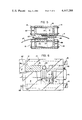
- FIG. 4 is a longitudinal sectional view on line 4--4 of FIG. 3, with distant parts removed.
- FIG. 5 is a cross-sectional view as on line 5--5 of FIG. 4.
- FIG. 6 is a plan sectional view on line 6--6 of FIG. 4, parts being broken away and in section.
- FIG. 7 is a cross-sectional view on line 7--7 of FIG. 4.
- FIG. 8 is a cross-sectional view on line 8--8 of FIG. 5.
- the improved seam welder is rollably supported on two laterally opposite wheels 10, journaled in the ends of a transverse upper frame 11, preferably having upstanding side flanges 12 and end flanges 13.
- the upper frame 11 is supported on a lower frame assembly which comprises two laterally spaced upper longitudinal tubular frame members 14 and two laterally spaced lower longitudinal tubular frame members 15, the members 14 being secured to the underside of the upper frame 11.
- a block or guiding head 16 At the head or front end of the lower frame assembly is a block or guiding head 16 between the inner surfaces of the tubular frame members 14 and 15, and it is secured thereto by transverse bolts 17, as best seen in FIG. 5.
- the block 16 Viewed from the front end as in FIGS. 3 and 5, the block 16 has a horizontal upper slot 19 extending laterally inward from the right substantially parallel to the bottoms of upper tubes 14 and a horizontal lower slot 20 extending laterally inward from the left substantially parallel to the tops of the lower tubes 15.
- the slots 19 and 20 extend past the longitudinal centerline of the block 16 and overlap each other a predetermined amount.
- the horizontal center plane of the block is midway between the slots 19 and 20. Viewed from the front end the positions of the slots 19 and 20 give the block substantially an S-shape in appearance.
- the block is hollow above the slot 19 and below the slot 20 to save weight and material.
- a U-shaped handle 21 is preferably secured to the transverse upper frame 11 and extends rearwardly and inclines upwardly therefrom.
- the slots 19 and 20 provide guides for the marginal edges of two side-by-side thermoplastic-coated fabric panels P and P' to guide them in overlapping relation to a nip area at the rear side of the block 16, where hot air is directed through a welding nozzle 24 and tip 25 between the overlapping marginal edges, thereby rendering the thermoplastic coatings substantially molten so that when pressed together they become welded.
- Hot air is delivered from the hot air gun 26 supplied with incoming air through conduit 27.
- the panels P and P' are preferably fabric coated with a special vinyl composition in which the plasticizer is substantially inhibited against migration under adverse weather conditions and over long periods of time.
- the lower pressure roll 31 is driven through a sprocket chain 39 by a front drive roll 40 which is connected by a driven timing belt 41 to a rear drive roll 42.
- Idler sprockets may be provided to engage and tension the sprocket drive chains 32 and 39 in a wellknown manner.
- the timing belt 41 and roll 42 are driven by an air powered gear motor 43 through sprocket chains 44 and 45 and reduction gear 46 which increases the effective speed of the gear motor causing it to develop increased torque on the timing belt 41.
- the motor 43 is mounted on a wall of one of the lower tubular frame members 15.
- the shaft of the upper pressure roll 30 is journaled in blocks 48 which are movable in vertical channels 49 secured to upper tubular frame members 14 (FIG. 7), and the blocks are mounted on piston rods 50 yieldingly urged downwardly by pneumatic cylinders 51 to load the roll 30 downwardly against the fabric.
- the upper drive rolls 33 and 34 are journaled in blocks 52 movable in vertical channels 53 secured to upper frame members 14 (FIG. 8), and the blocks are mounted on piston rods 54 yieldingly urged downwardly by smaller pneumatic cylinders 55 to load the rolls 33 and 35 downwardly against the fabric.
- the shafts of the lower rolls 31, 40 and 42 are journaled in bearings 46 which are fixedly mounted in tubular frame members 15.
- a cable 58 conducts electric current from a power source to a junction box 59 from which current is supplied to electric motor 36 and to the heating elements in hot air gun 26 by conventional wiring (not shown).
- Air is conducted from a compressor (not shown) by a conduit 60 through an air regulator 61 and oiler 62 to a junction with three branch conduits 63, 64 and 65, each having air regulators 66 therein.
- the conduit 63 supplies air to the cylinders 51 and conduit 64 supplies air to the cylinders 55.
- the conduit 65 supplies air to the gear motor 43 through devious interconnected conduits 67, 68 and 69 (FIGS. 3-5) extending forwardly through one upper tubular frame member 14, across through block 16 and then rearwardly through a laterally opposite lower tubular frame member 15.
- the edge portions of two panels P and P' are passed into the slots 19 and 20 in the block 16 from which their marginal edges emerge in overlapping relation into the nip area where the tip 25 applies hot air between the overlapping marginal edges to render the coatings on their inner surfaces substantially molten.
- the overlapping portions are pressed and welded together between pressure rolls 30 and 31, and then passed between the timing belts 34 and 41 connecting the rolls 33 and 35 and 40 and 42, respectively.
- the passage of the welded seam S through the belts assists in cooling the seam and also pulls the membrane through the pressure rolls 30 and 31 to produce a wrinkle-free seam because the outer diameter of the drive rolls is slightly greater than that of the pressure rolls 30 and 31. If the panels P and P' are stationary relative to the ground, the passage of the welded seam through the pressure rolls and timing belts causes the machine to be driven over the panels in the direction of the arrow A in FIG. 4.
- the air-powered gear motor 43 is not rotated at a given speed as is the electric motor 36, but applies torque to the lower pressure roll 31 and the lower timing belt 41 so as to follow the speed of the upper pressure roll 30 and upper timing belt 34 as driven by the electric motor 36.
- the air motor causes the lower pressure roll and belt assembly to match the speed of the upper pressure roll and belt assembly, thereby insuring a smooth and wrinkle-free seam.
- An important feature of the improved machine is that behind the head 16 the machine is completely open laterally or "throatless" in the plane of the seam, so that there are no guides or restrictions to restrain passage of the panels through the upper and lower pressure rolls and belt assemblies regardless of the panel widths, which would cause difficulties in passage or wrinkling at the seam. Also, the plane of the overlapping edges of the panels P and P' and the welded seam S in passing through the machine is close to the ground at all times so that the overlappings are lifted only a short distance.
- the improved seam welder provides a lightweight machine adapted to produce high quality thermally welded weather and chemical-resistant seams over uneven ground in the field by lifting the marginal edge portions of adjoining membrane panels off the ground as it passes thereover, and providing its own pressure and hot air welding conditions independently of the underlying ground surface.
Abstract
Description
Claims (15)
Priority Applications (1)
| Application Number | Priority Date | Filing Date | Title |
|---|---|---|---|
| US06/403,470 US4447288A (en) | 1982-07-30 | 1982-07-30 | Seam welder for thermoplastic coated fabric |
Applications Claiming Priority (1)
| Application Number | Priority Date | Filing Date | Title |
|---|---|---|---|
| US06/403,470 US4447288A (en) | 1982-07-30 | 1982-07-30 | Seam welder for thermoplastic coated fabric |
Publications (1)
| Publication Number | Publication Date |
|---|---|
| US4447288A true US4447288A (en) | 1984-05-08 |
Family
ID=23595900
Family Applications (1)
| Application Number | Title | Priority Date | Filing Date |
|---|---|---|---|
| US06/403,470 Expired - Fee Related US4447288A (en) | 1982-07-30 | 1982-07-30 | Seam welder for thermoplastic coated fabric |
Country Status (1)
| Country | Link |
|---|---|
| US (1) | US4447288A (en) |
Cited By (30)
| Publication number | Priority date | Publication date | Assignee | Title |
|---|---|---|---|---|
| EP0258984A2 (en) * | 1986-09-03 | 1988-03-09 | UNIROYAL CHEMICAL COMPANY, Inc. | Method for heat sealing thermoplastic membranes |
| US4737212A (en) * | 1983-05-20 | 1988-04-12 | Pfaff Industriemaschinen Gmbh | Method for connecting together material plies which are unilaterally thermoplastically coated |
| US4743332A (en) * | 1986-12-12 | 1988-05-10 | Black William E | Hot plate welding device for bonding roofing membranes |
| US4744855A (en) * | 1985-10-12 | 1988-05-17 | Pfaff Industriemaschinen Gmbh | Welding machine for foil webs |
| US4806194A (en) * | 1988-03-07 | 1989-02-21 | Wald Richard D | Roofing paper applicator |
| US4855004A (en) * | 1987-06-26 | 1989-08-08 | Clements National Company | Seam welding machine for thermoplastic material |
| US4872941A (en) * | 1987-11-09 | 1989-10-10 | Lippman Glenn W | Automatic welding apparatus for welding thermoplastic materials in sheet form |
| US5378302A (en) * | 1992-03-06 | 1995-01-03 | Meistermatic Ag | Traveling large-area welding machine for welding plastic sheets |
| US5399226A (en) * | 1990-09-11 | 1995-03-21 | Flexible Steel Lacing Company | Method and apparatus for attaching cleats |
| US5439540A (en) * | 1992-09-18 | 1995-08-08 | Technocorp Inc. | Method and apparatus for applying sheet material to a base surface |
| BE1008653A3 (en) * | 1994-08-23 | 1996-07-02 | Pol Transport Naamloze Vennoot | Device for joining foils |
| US5624511A (en) * | 1994-10-27 | 1997-04-29 | Glenn W. Lippman | Method and apparatus for joining heat sealable material |
| FR2750070A1 (en) * | 1996-06-21 | 1997-12-26 | Griltex | Self-driven thermal moulding machine |
| US5865942A (en) * | 1996-02-14 | 1999-02-02 | Sinclair; Frank | Seam welder |
| US5897721A (en) * | 1997-07-17 | 1999-04-27 | Olympic General Corporation | Liner with integrated cable and method |
| US6032714A (en) * | 1998-05-01 | 2000-03-07 | Fenton; Jay Thomas | Repeatably positionable nozzle assembly |
| US6053230A (en) * | 1997-10-24 | 2000-04-25 | Pelland Automation, Inc. | Rotary hot air welder |
| US6129809A (en) * | 1997-12-19 | 2000-10-10 | G.M. Pfaff Aktiengesellschaft | Heat-sealing machine |
| US6170550B1 (en) * | 1998-02-06 | 2001-01-09 | Leister Process Technologies | Pressing device for welding sealing webs |
| US6186210B1 (en) * | 1997-11-03 | 2001-02-13 | Wegener Gmbh | Heat sealing device |
| US6213184B1 (en) | 1996-02-14 | 2001-04-10 | Frank Sinclair | Seam welder |
| US6471803B1 (en) * | 1997-10-24 | 2002-10-29 | Ray Pelland | Rotary hot air welder and stitchless seaming |
| US6610159B2 (en) | 2001-07-27 | 2003-08-26 | Bfs Diversified Products, Llc | Obstruction avoidance continuous seam welding system |
| US20040011459A1 (en) * | 2002-05-13 | 2004-01-22 | Henegar Jeffrey W. | Obstruction avoidance continuous seam welding system |
| US20040246179A1 (en) * | 2003-06-04 | 2004-12-09 | Auden Techno Corp. | Multi-frequency antenna with single layer and feeding point |
| US20080286552A1 (en) * | 2005-07-06 | 2008-11-20 | Tapio Kordelin | Method for Manufacturing of Cellular Board, Cellular Board, Method for Producing Cellular Board Element of Steel Plate Strip, and Production Line |
| AU2011253543B2 (en) * | 2005-11-08 | 2013-05-02 | Neapo Oy | System and Method for Manufacturing Cellular Board |
| USD719596S1 (en) | 2012-12-20 | 2014-12-16 | Sfs Intec Holding Ag | Induction apparatus |
| WO2016020470A1 (en) * | 2014-08-08 | 2016-02-11 | Rema Tip Top Ag | Double-acting roller |
| US20180257309A1 (en) * | 2016-01-14 | 2018-09-13 | Shady Lane Curtains, Llc | Method of Making a Barn Curtain With Joined Panels |
Citations (3)
| Publication number | Priority date | Publication date | Assignee | Title |
|---|---|---|---|---|
| US3402089A (en) * | 1964-08-24 | 1968-09-17 | Domestic Film Products Corp | Method and apparatus for welding fabric with a thermoplastic seam |
| US3986918A (en) * | 1972-08-28 | 1976-10-19 | Erling Berner | Apparatus for forming laminated molded bodies |
| US4259142A (en) * | 1979-10-22 | 1981-03-31 | Kortepeter Dale T | Machine for applying roofing material |
-
1982
- 1982-07-30 US US06/403,470 patent/US4447288A/en not_active Expired - Fee Related
Patent Citations (3)
| Publication number | Priority date | Publication date | Assignee | Title |
|---|---|---|---|---|
| US3402089A (en) * | 1964-08-24 | 1968-09-17 | Domestic Film Products Corp | Method and apparatus for welding fabric with a thermoplastic seam |
| US3986918A (en) * | 1972-08-28 | 1976-10-19 | Erling Berner | Apparatus for forming laminated molded bodies |
| US4259142A (en) * | 1979-10-22 | 1981-03-31 | Kortepeter Dale T | Machine for applying roofing material |
Cited By (36)
| Publication number | Priority date | Publication date | Assignee | Title |
|---|---|---|---|---|
| US4737212A (en) * | 1983-05-20 | 1988-04-12 | Pfaff Industriemaschinen Gmbh | Method for connecting together material plies which are unilaterally thermoplastically coated |
| US4744855A (en) * | 1985-10-12 | 1988-05-17 | Pfaff Industriemaschinen Gmbh | Welding machine for foil webs |
| US4737213A (en) * | 1986-09-03 | 1988-04-12 | Uniroyal Chemical Company, Inc. | Method for heat sealing thermoplastic membranes |
| EP0258984A3 (en) * | 1986-09-03 | 1988-10-12 | Uniroyal Chemical Company, Inc. | Method for heat sealing thermoplastic membranes |
| EP0258984A2 (en) * | 1986-09-03 | 1988-03-09 | UNIROYAL CHEMICAL COMPANY, Inc. | Method for heat sealing thermoplastic membranes |
| US4743332A (en) * | 1986-12-12 | 1988-05-10 | Black William E | Hot plate welding device for bonding roofing membranes |
| US4855004A (en) * | 1987-06-26 | 1989-08-08 | Clements National Company | Seam welding machine for thermoplastic material |
| US4872941A (en) * | 1987-11-09 | 1989-10-10 | Lippman Glenn W | Automatic welding apparatus for welding thermoplastic materials in sheet form |
| US4806194A (en) * | 1988-03-07 | 1989-02-21 | Wald Richard D | Roofing paper applicator |
| US5399226A (en) * | 1990-09-11 | 1995-03-21 | Flexible Steel Lacing Company | Method and apparatus for attaching cleats |
| US5378302A (en) * | 1992-03-06 | 1995-01-03 | Meistermatic Ag | Traveling large-area welding machine for welding plastic sheets |
| US5439540A (en) * | 1992-09-18 | 1995-08-08 | Technocorp Inc. | Method and apparatus for applying sheet material to a base surface |
| BE1008653A3 (en) * | 1994-08-23 | 1996-07-02 | Pol Transport Naamloze Vennoot | Device for joining foils |
| US5624511A (en) * | 1994-10-27 | 1997-04-29 | Glenn W. Lippman | Method and apparatus for joining heat sealable material |
| US5865942A (en) * | 1996-02-14 | 1999-02-02 | Sinclair; Frank | Seam welder |
| US6213184B1 (en) | 1996-02-14 | 2001-04-10 | Frank Sinclair | Seam welder |
| FR2750070A1 (en) * | 1996-06-21 | 1997-12-26 | Griltex | Self-driven thermal moulding machine |
| US6153033A (en) * | 1997-07-17 | 2000-11-28 | Olympic General Corporation | Liner with integrated cable and method |
| US5897721A (en) * | 1997-07-17 | 1999-04-27 | Olympic General Corporation | Liner with integrated cable and method |
| US6053230A (en) * | 1997-10-24 | 2000-04-25 | Pelland Automation, Inc. | Rotary hot air welder |
| US6471803B1 (en) * | 1997-10-24 | 2002-10-29 | Ray Pelland | Rotary hot air welder and stitchless seaming |
| US6186210B1 (en) * | 1997-11-03 | 2001-02-13 | Wegener Gmbh | Heat sealing device |
| US6129809A (en) * | 1997-12-19 | 2000-10-10 | G.M. Pfaff Aktiengesellschaft | Heat-sealing machine |
| US6170550B1 (en) * | 1998-02-06 | 2001-01-09 | Leister Process Technologies | Pressing device for welding sealing webs |
| US6032714A (en) * | 1998-05-01 | 2000-03-07 | Fenton; Jay Thomas | Repeatably positionable nozzle assembly |
| US6610159B2 (en) | 2001-07-27 | 2003-08-26 | Bfs Diversified Products, Llc | Obstruction avoidance continuous seam welding system |
| US6973951B2 (en) | 2002-05-13 | 2005-12-13 | Bfs Diversified Products, Llc | Obstruction avoidance continuous seam welding system |
| US20040011459A1 (en) * | 2002-05-13 | 2004-01-22 | Henegar Jeffrey W. | Obstruction avoidance continuous seam welding system |
| US20040246179A1 (en) * | 2003-06-04 | 2004-12-09 | Auden Techno Corp. | Multi-frequency antenna with single layer and feeding point |
| US20080286552A1 (en) * | 2005-07-06 | 2008-11-20 | Tapio Kordelin | Method for Manufacturing of Cellular Board, Cellular Board, Method for Producing Cellular Board Element of Steel Plate Strip, and Production Line |
| AU2011253543B2 (en) * | 2005-11-08 | 2013-05-02 | Neapo Oy | System and Method for Manufacturing Cellular Board |
| US8741418B2 (en) | 2005-11-08 | 2014-06-03 | Neapo Oy | Method for manufacturing of cellular board, cellular board, method for producing cellular board element of steel plate strip, and production line |
| USD719596S1 (en) | 2012-12-20 | 2014-12-16 | Sfs Intec Holding Ag | Induction apparatus |
| WO2016020470A1 (en) * | 2014-08-08 | 2016-02-11 | Rema Tip Top Ag | Double-acting roller |
| US20180257309A1 (en) * | 2016-01-14 | 2018-09-13 | Shady Lane Curtains, Llc | Method of Making a Barn Curtain With Joined Panels |
| US11534983B2 (en) * | 2016-01-14 | 2022-12-27 | Shady Lane Curtains, Llc | Method of making a barn curtain with joined panels |
Similar Documents
| Publication | Publication Date | Title |
|---|---|---|
| US4447288A (en) | Seam welder for thermoplastic coated fabric | |
| US7476055B2 (en) | Underground and partly submerged pipe winding apparatus and method | |
| US5169264A (en) | Propulsion process of buried pipe | |
| CN101730814B (en) | Method and apparatus for coating pipes | |
| US3166458A (en) | Large area sheet sealing | |
| CA2868335A1 (en) | Seamless pool liner and method of making the same | |
| US20110248072A1 (en) | Method and apparatus for coating pipes and pipe sections | |
| JPH0523586B2 (en) | ||
| US4990209A (en) | Self propelled pipe fusion machine | |
| US20050183831A1 (en) | Apparatus and method for welding overlapping water-proof membranes to each other | |
| CZ330996A3 (en) | Process for producing bags from single- or multilayer cut pieces of a paper hose and apparatus for making the same | |
| JPH0348392B2 (en) | ||
| US4747903A (en) | Gas fired plastic film seaming apparatus | |
| JP2010120224A (en) | Method for manufacturing jointed sheet | |
| CN2846514Y (en) | Leak-proof engineering cloth adhesive car | |
| US1954160A (en) | Metal pipe forming machine | |
| US8794290B2 (en) | Apparatus for creating an encased cable seam | |
| AU2002300784B2 (en) | Membrane jointing system | |
| CN110142976A (en) | A kind of overlay film greenhouse booth is by portable heat-sealing machine | |
| JPH0444153B2 (en) | ||
| JPH03290590A (en) | Jacking method of underground pipe | |
| CA1283520C (en) | Pipe fusion machine | |
| CN218346444U (en) | Roof waterproof structure for splicing seam of box-type house | |
| CN110329574B (en) | Weld joint film laminating equipment and weld joint film laminating method thereof | |
| CN217258507U (en) | Winding corrugated pipe shaping device |
Legal Events
| Date | Code | Title | Description |
|---|---|---|---|
| AS | Assignment |
Owner name: SEAMAN CORPORATION, MILLERSBURG, OH A CORP. OF OH Free format text: ASSIGNMENT OF ASSIGNORS INTEREST.;ASSIGNOR:SEAMAN, DONALD R.;REEL/FRAME:004033/0271 Effective date: 19820714 Owner name: SEAMAN CORPORATION, OHIO Free format text: ASSIGNMENT OF ASSIGNORS INTEREST;ASSIGNOR:SEAMAN, DONALD R.;REEL/FRAME:004033/0271 Effective date: 19820714 |
|
| FPAY | Fee payment |
Year of fee payment: 4 |
|
| REMI | Maintenance fee reminder mailed | ||
| LAPS | Lapse for failure to pay maintenance fees | ||
| FP | Lapsed due to failure to pay maintenance fee |
Effective date: 19920510 |
|
| STCH | Information on status: patent discontinuation |
Free format text: PATENT EXPIRED DUE TO NONPAYMENT OF MAINTENANCE FEES UNDER 37 CFR 1.362 |