US4440524A - Process for bringing a body of water into communication with a tunnel - Google Patents
Process for bringing a body of water into communication with a tunnel Download PDFInfo
- Publication number
- US4440524A US4440524A US06/263,384 US26338481A US4440524A US 4440524 A US4440524 A US 4440524A US 26338481 A US26338481 A US 26338481A US 4440524 A US4440524 A US 4440524A
- Authority
- US
- United States
- Prior art keywords
- cavity
- tunnel
- roof
- pipe
- length
- Prior art date
- Legal status (The legal status is an assumption and is not a legal conclusion. Google has not performed a legal analysis and makes no representation as to the accuracy of the status listed.)
- Expired - Fee Related
Links
- XLYOFNOQVPJJNP-UHFFFAOYSA-N water Substances O XLYOFNOQVPJJNP-UHFFFAOYSA-N 0.000 title claims abstract description 27
- 238000000034 method Methods 0.000 title claims abstract description 23
- 238000004891 communication Methods 0.000 title claims abstract description 6
- 238000010276 construction Methods 0.000 claims description 6
- 238000004873 anchoring Methods 0.000 claims description 5
- 238000009434 installation Methods 0.000 abstract description 12
- 238000005553 drilling Methods 0.000 description 6
- 239000002360 explosive Substances 0.000 description 6
- 238000005422 blasting Methods 0.000 description 2
- 238000007667 floating Methods 0.000 description 2
- 239000002184 metal Substances 0.000 description 2
- 230000001681 protective effect Effects 0.000 description 2
- 239000011435 rock Substances 0.000 description 2
- 229920003002 synthetic resin Polymers 0.000 description 2
- 239000000057 synthetic resin Substances 0.000 description 2
- 229910000831 Steel Inorganic materials 0.000 description 1
- 238000009412 basement excavation Methods 0.000 description 1
- 230000000903 blocking effect Effects 0.000 description 1
- 238000005520 cutting process Methods 0.000 description 1
- 230000000694 effects Effects 0.000 description 1
- 239000003822 epoxy resin Substances 0.000 description 1
- 238000004880 explosion Methods 0.000 description 1
- 239000012530 fluid Substances 0.000 description 1
- 229930195733 hydrocarbon Natural products 0.000 description 1
- 150000002430 hydrocarbons Chemical class 0.000 description 1
- 230000000977 initiatory effect Effects 0.000 description 1
- 238000004519 manufacturing process Methods 0.000 description 1
- 238000005065 mining Methods 0.000 description 1
- 238000012986 modification Methods 0.000 description 1
- 230000004048 modification Effects 0.000 description 1
- 229920000647 polyepoxide Polymers 0.000 description 1
- 238000002360 preparation method Methods 0.000 description 1
- 229920005989 resin Polymers 0.000 description 1
- 239000011347 resin Substances 0.000 description 1
- 238000007789 sealing Methods 0.000 description 1
- 239000010959 steel Substances 0.000 description 1
- 238000009423 ventilation Methods 0.000 description 1
- 238000003466 welding Methods 0.000 description 1
Images


Classifications
-
- E—FIXED CONSTRUCTIONS
- E21—EARTH OR ROCK DRILLING; MINING
- E21D—SHAFTS; TUNNELS; GALLERIES; LARGE UNDERGROUND CHAMBERS
- E21D9/00—Tunnels or galleries, with or without linings; Methods or apparatus for making thereof; Layout of tunnels or galleries
-
- E—FIXED CONSTRUCTIONS
- E02—HYDRAULIC ENGINEERING; FOUNDATIONS; SOIL SHIFTING
- E02D—FOUNDATIONS; EXCAVATIONS; EMBANKMENTS; UNDERGROUND OR UNDERWATER STRUCTURES
- E02D29/00—Independent underground or underwater structures; Retaining walls
- E02D29/06—Constructions, or methods of constructing, in water
-
- E—FIXED CONSTRUCTIONS
- E21—EARTH OR ROCK DRILLING; MINING
- E21B—EARTH OR ROCK DRILLING; OBTAINING OIL, GAS, WATER, SOLUBLE OR MELTABLE MATERIALS OR A SLURRY OF MINERALS FROM WELLS
- E21B43/00—Methods or apparatus for obtaining oil, gas, water, soluble or meltable materials or a slurry of minerals from wells
- E21B43/01—Methods or apparatus for obtaining oil, gas, water, soluble or meltable materials or a slurry of minerals from wells specially adapted for obtaining from underwater installations
-
- E—FIXED CONSTRUCTIONS
- E21—EARTH OR ROCK DRILLING; MINING
- E21B—EARTH OR ROCK DRILLING; OBTAINING OIL, GAS, WATER, SOLUBLE OR MELTABLE MATERIALS OR A SLURRY OF MINERALS FROM WELLS
- E21B43/00—Methods or apparatus for obtaining oil, gas, water, soluble or meltable materials or a slurry of minerals from wells
- E21B43/30—Specific pattern of wells, e.g. optimising the spacing of wells
- E21B43/305—Specific pattern of wells, e.g. optimising the spacing of wells comprising at least one inclined or horizontal well
-
- E—FIXED CONSTRUCTIONS
- E21—EARTH OR ROCK DRILLING; MINING
- E21D—SHAFTS; TUNNELS; GALLERIES; LARGE UNDERGROUND CHAMBERS
- E21D13/00—Large underground chambers; Methods or apparatus for making them
Definitions
- the present invention relates to a process for use in making a connection between a body of water, such as a sea or a lake, and a tunnel excavated under the bed of the body of water.
- the process is applicable to any construction made on the bed of a sea or of a lake from at least one tunnel, particularly but not exclusively for the purposes of mining or oil drilling or production.
- a process for bringing a body of water into communication with a tunnel under the bed of said body of water comprising excavating beneath the end portion of said tunnel which is adjacent said body of water an underground cavity having a volume at least equal to the volume of the ground between said body of water and said tunnel and above said cavity, and which thus forms the roof of said cavity, and then causing said roof of said cavity to collapse.
- the roof is preferably caused to collapse by a plurality of mine blasts carried out with small explosive charges placed in holes which are distributed over the roof and are made from the interior of the tunnel and/or from the surface of the body of water.
- the tunnel may be a single tunnel or one of a plurality of tunnels forming a tunnel system.
- the tunnel and the cavity may be provided, for example, for protecting equipment against the action of icebergs or ice at the bottom of the body of water, and/or for gaining more convenient access to a given immersed location.
- constructions useful for work which is to be carried out, if appropriate, after the roof has been collapsed may be installed in the cavity.
- the installation plan is advantageously studied with a view to increasing the number of operations which are carried out before the roof is collapsed, and with a view to reducing the number of operations which have to be carried out after the roof has been collapsed.
- At least one length of pipe such as a pipe for conveying hydrocarbons, may be placed in the tunnel, and leaktight shields may be provided between the walls of the tunnel and the pipe in the tunnel, before the roof is collapsed.
- leaktight shields may be provided between the walls of the tunnel and the pipe in the tunnel, before the roof is collapsed.
- tubes for use in controlling the leaktightness of an intermediate space located between the shields are provided.
- the leaktight shields are advantageously anchored in the walls of the tunnel.
- the pipe is advantageously anchored in the tunnel.
- the cavity is used to receive the debris from the roof after it has been collapsed. However, it is advantageously also used during the installation of certain constructions before the roof is collaped, as has been stated above.
- the constructions may comprise, for example, a lining forming a chamber for protecting devices positioned prior to collapsing the roof, or of supports, such as beams, intended for holding devices positioned afterwards, such as a length of pipe which is to be connected to the end of the pipe placed in the tunnel.
- This latter case may arise, in particular, if it is desired to provide a pipe between a land installation and a sea installation, when the surface of the seabed in the vicinity of the coast is very undulating, and when it thus appears preferable to join the land installation to a more distant point on the seabed by means of a tunnel, or if it is desired to protect a pipe from dangers created by icebergs and/or bottom ice in certain regions of the world. Placing a pipe in the tunnel obviously presents no difficulty; moveover, various techniques for laying immersed pipes are known.
- the problem which has not yet been solved concerns the manner in which the tunnel is opened into the body of water and a connection, in the zone where the tunnel opens into the body of water, is made with the underground pipe arranged in the tunnel, and, for example, with the immersed pipe, where provided.
- FIG. 1 is a schematic section showing the profile of an underground tunnel
- FIG. 2 is a schematic vertical section through the marine end of the tunnel of FIG. 1 and of an underground cavity, before collapsing the roof of the latter, according to a first embodiment of the invention
- FIG. 3 is a section on the line 3--3 of FIG. 2;
- FIG. 4 is a section on the line 4--4 of FIG. 2;
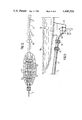
- FIG. 5 is a perspective view, to an enlarged scale, of a device for protecting the end of the length of underground pipe;
- FIG. 6 is a longitudinal section, to an enlarged scale, through a length of tunnel and pipe, showing leak tight shields;
- FIG. 7 is a schematic vertical section in the region of the cavity at the moment when the operation for collapsing the roof of the cavity is about to start;
- FIG. 8 is an analogous section to that of FIG. 7, shown during the operation of collapsing the roof of the cavity;
- FIG. 9 is a plan view showing the location of explosive charges used for collapsing the roof.
- FIG. 10 is an analogous section to that of FIGS. 7 and 8, showing the cavity at the end of the operation of collapsing the roof;
- FIG. 11 is a schematic vertical section in the region of the cavity showing the connection of an underground pipe and an immersed pipe;
- FIG. 12 is a plan view of the same region.
- FIG. 13 is a longitudinal section showing a length of a tunnel and of a drilling well, in another embodiment according to the invention.
- land installations 1 are to be joined to an immersed length of pipe 2 on the seabed at a depth 3 of, for example, about 100 meters and located at a distance of, for example, about 20 kilometers from the installations 1.
- a depth 3 of, for example, about 100 meters and located at a distance of, for example, about 20 kilometers from the installations 1.
- the coast 4 is separated from the end of the pipe 2 by a depression 5 having a depth of, for example, 300 meters, and by an island 6, it appears desirable to join the installations 1 to the pipe 2 by means of a pipe 7 arranged underground in a tunnel 8.
- This tunnel is provided with ventilation shafts such as 9 and 10.
- the work and installations are carried out in hard ground, and no mention will be made of the various well-known techniques which can be used for cutting and consolidating the tunnels depending on the nature of the ground.
- a cavity 11 is excavated at the marine end of the tunnel and under the tunnel, to a sufficient depth for it to have a reception volume at least equal to that of the ground which is between the sea and the tunnel and which constitutes the roof 12 of the cavity, which is subsequently to be collapsed into the cavity.
- An access ramp 13 is provided to enable vehicles to descend into the cavity 11 from the tunnel 8.
- Two recesses 14 and 15 are provided in the wall of the tunnel 8 for housing two leaktight shields 16 and 17, which can be seen in FIG. 6.
- an upper chamber 18 is excavated.
- a retaining framework of beams 19 for holding up the ground when the roof 12 is collapsed is assembled in chamber 18.
- a set of pillars 20 supporting beams 21 are installed in the cavity, and these beams provide a stable seating of predetermined and precise configuration for supporting a length of pipe as will be described.
- a device for protecting the end of the pipe 7 arranged in the tunnel 8 is also installed in the chamber 18.
- This device which is shown to an enlarged scale in FIG. 5, comprises a metal frame 22 which encloses the ends of the pipe 7, and an inclined roofing 23 which protects the end of the pipe against lumps of earth falling in from the roof 12 when the latter is collapsed.
- the location of the device is shown in FIG. 10 and the roofing 23 is shown in FIGS. 7 and 8.
- the protective device can eventually be removed simply by pulling from the surface, after hooking up, by divers, with the aid of suitable eyelets.
- FIG. 6 shows an embodiment of the leaktight shield, it being possible for other suitable blocking devices to be used depending on the nature of the ground and the tunnel.
- the length of pipe 7 is provided, at right-angles to the recesses 14 and 15, with extra thicknesses of weld 24 of non-oxidisable metal, which can be covered with an electrically insulated resin.
- a mass of concrete 25 is poured into a casing, which is not shown.
- a few perforations may be made in the concrete and a synthetic resin, for example an epoxy resin as used in this type of work, is injected.
- the shield 16 is installed at a safe distance from the cavity 11, for example 10 meters, which is sufficient for it to be completely protective from the effects of the operations for collapsing the roof 12 of the cavity 11.
- a tube 26 may be provided extending through the shield 17, the tube 26 being joined to a manometer 27 via a three-way valve 28, and may bring the space 29 between the shields into communication with the interior of the tunnel 8 (for removing air from the space if appropriate), or with the manometer.
- a tube 30 may be provided extending through the shield 17, the tube 30 being connected to a pump 31 for placing the space 29 under pressure. It is thus possible to carryout a leaktightness test by filling the space 29 with a fluid under pressure and by checking that the pressure is maintained in the space 29, If the leaktightness appears inadequate, although it is then no longer possible to act on the shield 16, it is possible to inject synthetic resin into the shield 17. If the desired leaktightness were not achieved in this way, a third leaktight shield could be installed.
- the tubes 26 and 30 may either be plugged or maintained during the normal running of the installations, for the purpose of permanently checking the leaktightness of the shield 16.
- the anchoring of the shields 16 and 17 in the recesses 14 and 15 enables the shields 16 and 17 to withstand the thrust of the sea after the roof 12 of the cavity has been collapsed.
- the pipe 7 is temporarily plugged at its marine end, the pipe is also subject to the thrust of the sea after roof 12 has been collapsed. It is therefore advisable to provide an anchoring 32 for the pipe 7.
- the anchoring 32 which can be placed in front of or behind the shields, is provided as shown, by two collars 33,34 which are integral with the pipe 7, a gasket 35 being inserted between them, and which are clamped between two flanges 36,37 with the interposition of electrically insulating pieces 38,39, the two flanges 36,37 being carried by a plinth 40 anchored in the floor of the tunnel by means of sealed bolts such as 41,42.
- a positioning hole 43 is made in the roof 12 using a floating drilling apparatus (not shown).
- the holes intended for the explosive charges may be made from the surface and/or from the interior, before positioning the shields and with the installation of a device for initiating the explosion by remote-control.
- the roof consists in this case of rock, at least one hole is made in the zone 44, and at least one blast, directed downwards, is obtained using a small explosive charge.
- the operation then continues, as shown by the dotted lines 45 in FIG. 8, with small explosive charges so as to clear small lumps which accumulate as masses 46 in the bottom of the cavity 11.
- Explosive blasts can be carried out in accordance with various methods which are in themselves known.
- Various locations which can be used in one of these methods for making holes and carryingout blasts have been shown in FIG. 9 by means of crosses 47.
- a first hole which is a positioning hole, was made at 48, followed by a second hole, which was a blasting hole, at 49, and by a third hole, which was a blasting hole, at 50, whilst a hole 51 is in the course of preparation for the next blast, and the following holes and blasts are made and carried out at the locations marked.
- the masses 46 cover the whole of the bottom of the cavity 11, as shown in FIG. 10.
- the protecting device can then be raised to the surface.
- a pressure welding apparatus 56 is first positioned to weld the pipe length 53 to the underground pipe 7 at 54, and it is then moved to join the pipe length 53 to the end of the first section of the immersed pipe 2 at 55.
- the frame 52 and the length of pipe 53 have configurations corresponding to the characteristics of the site resulting from the work carried out previously and from the collapsing of the roof 12.
- the frame comprises an enclosure of protection bars 57 forming a cage, inside which personnel can work with protection from falls of rock which may occur.
- the body of water is a sea 58 in which there is frequently bottom ice.
- oil drilling, or collection, such as that indicated at 59, is to be carried out.
Landscapes
- Engineering & Computer Science (AREA)
- Mining & Mineral Resources (AREA)
- Life Sciences & Earth Sciences (AREA)
- Geology (AREA)
- General Life Sciences & Earth Sciences (AREA)
- Environmental & Geological Engineering (AREA)
- Geochemistry & Mineralogy (AREA)
- Fluid Mechanics (AREA)
- Physics & Mathematics (AREA)
- Paleontology (AREA)
- Civil Engineering (AREA)
- General Engineering & Computer Science (AREA)
- Structural Engineering (AREA)
- Excavating Of Shafts Or Tunnels (AREA)
- Sewage (AREA)
Applications Claiming Priority (2)
| Application Number | Priority Date | Filing Date | Title |
|---|---|---|---|
| FR8010997 | 1980-05-16 | ||
| FR8010997A FR2482656A1 (fr) | 1980-05-16 | 1980-05-16 | Procede de mise en communication entre une etendue d'eau et un tunnel creuse sous le fond de cette etendue d'eau |
Publications (1)
| Publication Number | Publication Date |
|---|---|
| US4440524A true US4440524A (en) | 1984-04-03 |
Family
ID=9242057
Family Applications (1)
| Application Number | Title | Priority Date | Filing Date |
|---|---|---|---|
| US06/263,384 Expired - Fee Related US4440524A (en) | 1980-05-16 | 1981-05-13 | Process for bringing a body of water into communication with a tunnel |
Country Status (10)
| Country | Link |
|---|---|
| US (1) | US4440524A (enExample) |
| JP (1) | JPS5751395A (enExample) |
| AR (1) | AR231325A1 (enExample) |
| AU (1) | AU533477B2 (enExample) |
| BR (1) | BR8103038A (enExample) |
| CA (1) | CA1170065A (enExample) |
| FR (1) | FR2482656A1 (enExample) |
| GB (1) | GB2076448B (enExample) |
| NO (1) | NO811666L (enExample) |
| OA (1) | OA06810A (enExample) |
Cited By (2)
| Publication number | Priority date | Publication date | Assignee | Title |
|---|---|---|---|---|
| US4671704A (en) * | 1984-08-30 | 1987-06-09 | Compagnie Francaise De Petroles | Coastal installation for loading or unloading liquid at cryogenic temperature |
| RU2164050C1 (ru) * | 1999-12-27 | 2001-03-10 | Филимонов Сергей Игоревич | Способ прокладки кабелей и полиэтиленовых трубопроводов под землей через береговую линию |
Families Citing this family (1)
| Publication number | Priority date | Publication date | Assignee | Title |
|---|---|---|---|---|
| US4397582A (en) * | 1981-03-31 | 1983-08-09 | Mcdermott Incorporated | Method of creating a cold water conduit to be used in ocean thermal energy conversion systems |
Citations (5)
| Publication number | Priority date | Publication date | Assignee | Title |
|---|---|---|---|---|
| DE2461454A1 (de) * | 1974-12-24 | 1976-07-01 | Ruhrkohle Ag | Verfahren zum ausbauen von durch sprengarbeit aufgefahrenen strecken des berg- und tunnelbaus |
| US4036024A (en) * | 1974-06-12 | 1977-07-19 | Bergwerksverband Gmbh | Device for closing off a mine gallery especially for use to prevent spreading of underground explosions |
| US4076130A (en) * | 1976-02-27 | 1978-02-28 | Hydrotech International, Inc. | Apparatus for mounting a coupling member over a pipe end in a subsea location |
| US4129010A (en) * | 1977-08-25 | 1978-12-12 | Montreal Engineering Company, Limited | Tunnel |
| US4167357A (en) * | 1978-05-05 | 1979-09-11 | Assad Ahmed A | Rapid construction of deep international ports, at shallow seashores, without dredging |
-
1980
- 1980-05-16 FR FR8010997A patent/FR2482656A1/fr active Granted
-
1981
- 1981-05-07 GB GB8114001A patent/GB2076448B/en not_active Expired
- 1981-05-13 US US06/263,384 patent/US4440524A/en not_active Expired - Fee Related
- 1981-05-15 CA CA000377676A patent/CA1170065A/fr not_active Expired
- 1981-05-15 NO NO811666A patent/NO811666L/no unknown
- 1981-05-15 BR BR8103038A patent/BR8103038A/pt unknown
- 1981-05-15 AU AU70632/81A patent/AU533477B2/en not_active Ceased
- 1981-05-16 JP JP56074069A patent/JPS5751395A/ja active Pending
- 1981-05-16 OA OA57403A patent/OA06810A/xx unknown
- 1981-05-18 AR AR285355A patent/AR231325A1/es active
Patent Citations (5)
| Publication number | Priority date | Publication date | Assignee | Title |
|---|---|---|---|---|
| US4036024A (en) * | 1974-06-12 | 1977-07-19 | Bergwerksverband Gmbh | Device for closing off a mine gallery especially for use to prevent spreading of underground explosions |
| DE2461454A1 (de) * | 1974-12-24 | 1976-07-01 | Ruhrkohle Ag | Verfahren zum ausbauen von durch sprengarbeit aufgefahrenen strecken des berg- und tunnelbaus |
| US4076130A (en) * | 1976-02-27 | 1978-02-28 | Hydrotech International, Inc. | Apparatus for mounting a coupling member over a pipe end in a subsea location |
| US4129010A (en) * | 1977-08-25 | 1978-12-12 | Montreal Engineering Company, Limited | Tunnel |
| US4167357A (en) * | 1978-05-05 | 1979-09-11 | Assad Ahmed A | Rapid construction of deep international ports, at shallow seashores, without dredging |
Cited By (2)
| Publication number | Priority date | Publication date | Assignee | Title |
|---|---|---|---|---|
| US4671704A (en) * | 1984-08-30 | 1987-06-09 | Compagnie Francaise De Petroles | Coastal installation for loading or unloading liquid at cryogenic temperature |
| RU2164050C1 (ru) * | 1999-12-27 | 2001-03-10 | Филимонов Сергей Игоревич | Способ прокладки кабелей и полиэтиленовых трубопроводов под землей через береговую линию |
Also Published As
| Publication number | Publication date |
|---|---|
| BR8103038A (pt) | 1982-02-09 |
| CA1170065A (fr) | 1984-07-03 |
| FR2482656B1 (enExample) | 1983-06-03 |
| OA06810A (fr) | 1982-12-31 |
| GB2076448B (en) | 1983-09-28 |
| AR231325A1 (es) | 1984-10-31 |
| NO811666L (no) | 1981-11-17 |
| JPS5751395A (en) | 1982-03-26 |
| GB2076448A (en) | 1981-12-02 |
| AU533477B2 (en) | 1983-11-24 |
| FR2482656A1 (fr) | 1981-11-20 |
| AU7063281A (en) | 1981-11-19 |
Similar Documents
| Publication | Publication Date | Title |
|---|---|---|
| CN101975067B (zh) | 小断面泥水盾构粉细砂层接收方法 | |
| US4619556A (en) | Method and apparatus for severing a tubular member | |
| US5199816A (en) | System for isolating a dump | |
| CN105041322A (zh) | 顶管机进出洞的加固方法及加固系统 | |
| JP2023113780A (ja) | 地下トンネルを建設する方法及びシステム | |
| US4440524A (en) | Process for bringing a body of water into communication with a tunnel | |
| CN111022050B (zh) | 一种注浆改造复合顶板的全闭合爆破卸压及自留巷方法 | |
| CN109681229B (zh) | 隧道止水组件 | |
| US4422798A (en) | Process for construction of an underground structure and the structure thus obtained | |
| JP2009068213A (ja) | ケーソンを用いた地下構造物の構築方法および止水装置付ケーソン | |
| CN114233383A (zh) | 一种露天煤矿储水系统的建造方法 | |
| US4112690A (en) | Method and construction of underground tank well | |
| US3482408A (en) | Telescoped caisson | |
| KR102197032B1 (ko) | 해체를 용이하게 하는 작업구용 강관의 구조 | |
| US4129010A (en) | Tunnel | |
| CN114810099A (zh) | 超薄岩层特大跨度高铁隧道开挖施工方法 | |
| JPWO2020193960A5 (enExample) | ||
| US3216200A (en) | Underground pressure vessel construction method | |
| JPH0312633B2 (enExample) | ||
| JPS5664028A (en) | Sheathing construction work by antecedent support framework | |
| SU756045A1 (ru) | Способ образования вертикальной выработки в закладочном массиве 1 | |
| CN117248962B (zh) | 治理小窑巷柱式遗留煤柱间老空水的方法 | |
| CN116378751B (zh) | 一种下向瓦斯抽采定长钻孔的自动排水方法和系统 | |
| JPH07259078A (ja) | シ−ルド開口部用鋼材および地下連続壁の構築方法およ び立坑の鏡開き方法 | |
| CN115584982A (zh) | 用于盾构机进洞的水下洞门封堵方法 |
Legal Events
| Date | Code | Title | Description |
|---|---|---|---|
| AS | Assignment |
Owner name: COMPAGNIE FRANCAISE DES PETROLES, 5, MICHEAL ANGE Free format text: ASSIGNMENT OF ASSIGNORS INTEREST.;ASSIGNOR:LE THERISIN, LOUIS;REEL/FRAME:004200/0817 Effective date: 19810508 |
|
| FEPP | Fee payment procedure |
Free format text: MAINTENANCE FEE REMINDER MAILED (ORIGINAL EVENT CODE: REM.); ENTITY STATUS OF PATENT OWNER: LARGE ENTITY |
|
| LAPS | Lapse for failure to pay maintenance fees | ||
| STCH | Information on status: patent discontinuation |
Free format text: PATENT EXPIRED DUE TO NONPAYMENT OF MAINTENANCE FEES UNDER 37 CFR 1.362 |
|
| FP | Lapsed due to failure to pay maintenance fee |
Effective date: 19880403 |