US4439735A - Method and apparatus for testing line screen CRT registration - Google Patents
Method and apparatus for testing line screen CRT registration Download PDFInfo
- Publication number
- US4439735A US4439735A US06/284,031 US28403181A US4439735A US 4439735 A US4439735 A US 4439735A US 28403181 A US28403181 A US 28403181A US 4439735 A US4439735 A US 4439735A
- Authority
- US
- United States
- Prior art keywords
- electron beam
- purity
- targets
- crt
- current
- Prior art date
- Legal status (The legal status is an assumption and is not a legal conclusion. Google has not performed a legal analysis and makes no representation as to the accuracy of the status listed.)
- Expired - Fee Related
Links
- 238000012360 testing method Methods 0.000 title claims abstract description 59
- 238000000034 method Methods 0.000 title claims abstract description 14
- 238000010894 electron beam technology Methods 0.000 claims abstract description 58
- OAICVXFJPJFONN-UHFFFAOYSA-N Phosphorus Chemical compound [P] OAICVXFJPJFONN-UHFFFAOYSA-N 0.000 claims abstract description 46
- 230000004044 response Effects 0.000 claims description 3
- 238000012545 processing Methods 0.000 claims description 2
- 238000010998 test method Methods 0.000 abstract description 2
- 238000005259 measurement Methods 0.000 description 13
- 238000004519 manufacturing process Methods 0.000 description 5
- 238000006243 chemical reaction Methods 0.000 description 4
- 238000012935 Averaging Methods 0.000 description 3
- 238000010586 diagram Methods 0.000 description 3
- 230000004075 alteration Effects 0.000 description 2
- 230000003750 conditioning effect Effects 0.000 description 2
- 238000006073 displacement reaction Methods 0.000 description 2
- 230000000694 effects Effects 0.000 description 2
- 238000012986 modification Methods 0.000 description 2
- 230000004048 modification Effects 0.000 description 2
- 238000010276 construction Methods 0.000 description 1
- 230000001419 dependent effect Effects 0.000 description 1
- 230000008021 deposition Effects 0.000 description 1
- 238000011161 development Methods 0.000 description 1
- 230000008569 process Effects 0.000 description 1
- 238000003908 quality control method Methods 0.000 description 1
- 238000007670 refining Methods 0.000 description 1
- 230000000717 retained effect Effects 0.000 description 1
- 238000012956 testing procedure Methods 0.000 description 1
- 230000000007 visual effect Effects 0.000 description 1
Images


Classifications
-
- G—PHYSICS
- G01—MEASURING; TESTING
- G01R—MEASURING ELECTRIC VARIABLES; MEASURING MAGNETIC VARIABLES
- G01R31/00—Arrangements for testing electric properties; Arrangements for locating electric faults; Arrangements for electrical testing characterised by what is being tested not provided for elsewhere
- G01R31/24—Testing of discharge tubes
- G01R31/25—Testing of vacuum tubes
- G01R31/257—Testing of beam-tubes, e.g. cathode-ray tubes, image pick-up tubes
Definitions
- This invention is directed generally to improvements in the testing of line screen CRTs (cathode ray tubes). It is particularly directed to a method and apparatus for detecting the degree of misregistration between a line screen CRT's electron beam and the phosphor stripes which the beam is intended to excite.
- misregistration For a color CRT to develop an image of high brightness and high purity, the CRT's electron beams must impinge on the proper phosphor stripes. The extent to which the electron beams stray from their intended targets is referred to as misregistration.
- misregistration if any, depends upon a number of factors, but it is particularly dependent upon the quality of the light house lens which is used in the deposition of phosphor targets on the CRT screen. Developing a lens to achieve good registration has been a very time consuming process which is subject to human error.
- One step in the development of a good lens involves measuring the misregistraton of a CRT made with a prototype lens, and then modifying the lens to eliminate or reduce the measured misregistration.
- the measurement of misregistration includes first constructing a CRT with oversize phosphor targets, energizing the CRT, and then photographing multiple areas of the CRT screen under electron beam bombardment. After developing the photographs, measurements are made on the photographs to determine the distance between the center of the electron beam and the center of its phosphor target. Based on those measurements, the prototype lens may be refined to reduce the CRT's misregistration, and another set of measurements may be made to confirm that the lens achieves its objective.
- FIG. 1 illustrates a CRT under test, a test fixture, and a schematic representation of registration measurement circuitry for use in testing the misregistration of the CRT according to the invention
- FIG. 2 shows the rear of the test fixture illustrated in FIG. 1;
- FIG. 3 is a sectional view of a portion of the test fixture to illustrate how an exemplary light sensor and a filter are disposed in the test fixture;
- FIG. 4 depicts a single phosphor stripe located at one test area of the CRT, an electron beam spot, and a curve illustrating the sensed light output of the phosphor stripe as the beam spot is stepped across the phosphor stripe;
- FIG. 5 is a block diagram showing the registration measurement circuitry shown in FIG. 1 in more detail and the way in which it interfaces with a CRT under test;
- FIG. 6 is a detailed circuit diagram of a portion of the set up circuit shown in FIG. 5;
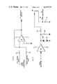
- FIG. 7 is a detailed circuit diagram of the purity coil driver circuit shown in FIG. 5;
- FIGS. 8A and 8B constitute a flow chart illustrating how the central processor of FIG. 5 may be programmed.
- a test fixture 10 is shown mated with a line screen CRT 12 whose registration is to be measured in accordance with the procedure described below.
- a plurality of test areas are selected on the screen of the CRT, the light output of each test area is sensed by light sensors 14 disposed on the test fixture, and the outputs of the light sensors are applied to registration measurement circuitry 16.
- the latter device causes the CRT's electron beam to be stepped across its phosphor stripe targets on the screen of the CRT, and records data for a plurality of beam locations to compute misregistration.
- the fixture 10 may include 99 light sensors arranged in a pattern for sensing the light output of each of 99 test areas on the CRT screen. To hold the test fixture in alignment with the screen, three pins 18 are mounted on the panel for engaging the skirt of the CRT's faceplate. In addition, vacuum assisted suction cups 20 (FIG. 2) may be disposed on the rear surface of the test fixture for holding it against the screen of the CRT.
- a field of substantially uniform color is established on the CRT screen.
- the center gun typically, the green gun
- the usual CRT deflection circuitry (not shown) is activated for establishing a raster of green, for example, on the CRT screen.
- each of the light sensors 14 photo resistors, for example
- a green filter 22 is disposed in front of the light sensor. The purpose of the recess is to ensure that only the light from a designated test area is received by the light sensing device.
- the filter 22 substantially excludes or limits all light from impinging on the light sensor except that which is the color which the activated electron gun is intended to produce.
- Each of the light sensors is preferably adapted to sense a circular test area having a diameter of about one quarter inch for averaging the light output of a plurality of phosphor stripes encompassed within the test area.
- FIG. 4 illustrates a single phosphor stripe 24 encompassed within a test area, an electron beam spot 26, and a curve 28 which represents the measured light output of the test area at various positions of the electron beam spot.
- the electron beam is incrementally stepped across the phosphor stripe by, for example, disposing a purity coil around the neck of the CRT and incrementally increasing current in the purity coil to step the electron beam across its phosphor target. It will be appreciated that in a line screen CRT with vertically oriented phosphor stripes, misregistration will only be a problem in the horizontal direction.
- the electron beam spot is situated at one side of the phosphor stripe 24 in a starting position.
- the illustrated position of the spot may be obtained by deflecting the electron beam there by means of current in the purity coil, or the beam may land in the illustrated position naturally when the current in the purity coil equals zero.
- the electron beam spot is assumed to be at its starting position with a purity coil current of zero.
- the output of the line sensor which detects light from the phosphor stripe 24 is measured.
- the value of light indicated at 30 on the curve 28 may correspond to the light emitted by the phosphor stripe when the electron beam is in its starting position.
- the electron beam is stepped to the right, and the light output of the phosphor stripe is again measured and stored.
- the value of light at this new position of the electron beam is indicated at 32 on the curve 28.
- the position of the electron beam continues to be stepped across the phosphor stripe at least until the registration measurement circuitry determines that a position of maximum light has been obtained, as at position 34.
- the location of the electron beam may be stored along with the value of the light output by the phosphor stripe at each location.
- the degree of misregistration may be calculated as the distance between the electron beam spot locations 30 and 34.
- the same electron beam stepping, light output sensing, and computation is effected concurrently for each test area on the CRT screen.
- the registration measurement circuitry computes and stores a predetermined percentage of the measured maximum light output. In the present embodiment, 75% of the maximum light output is computed and stored. In the case where the registration measurement circuitry has a memory large enough to store each sensed value of light from the phosphor stripe and the location of the beam at which each value was measured, the memory may be searched to find the beam position locations at which 75% of the maximum light output was obtained. These locations are indicated as A and B in FIG.
- the distances A' and B' are averaged, as by adding the distance A' to the distance B' and dividing their sum by two.
- the result is a number (typically in thousandths of an inch) representing the extent of misregistration between the electron beam and its phorphor target.
- the registration measurement circuit may store only the maximum and minimum values of light output, and compute the values of light output which correspond to the 75% points A and B. Then the beam may be deflected by current in the purity coil back to the starting position shown in FIG. 4. Now the electron beam is again stepped across the phosphor stripe, the light output of the phosphor stripe is measured at each position of the beam, and the position of the beam is stored when the measured light output corresponds to the light output computed for position A. The electron beam continues to be stepped until the measured light output corresponds to that computed for position B and the position of the beam is stored. Misregistration is then computed as described above by averaging the distance A' and B'.
- FIG. 5 Apparatus for carrying out the steps described above and other procedures not previously described is illustrated in FIG. 5.
- a purity coil 36 is situated around the neck of the CRT 12 for adjusting the position of the electron beam. In effect, varying the current in the coil 36 changes the purity exhibited by the CRT.
- the outputs of the light sensors in the test fixture 10 may be coupled to a signal conditioning network 38.
- This network may include a conventional low pass R-C filter, one for each light sensor, to remove 60 cycle and other undesired components from the output of a light sensor.
- the filtered output of the network 38 is applied to a set up circuit 40 and a converter 42.
- the set up circuit 40 is used only in preparing the CRT for test. It may be adapted to receive the output of two photocells which straddle the center of the CRT screen, and preferably includes indicators which show an operator the light output of those two photocells. The operator then adjusts the yoke (not shown) of the CRT for maximum output from the two centrally located photocells. Thus, each CRT which is tested can be set up in the same manner to achieve repeatable measurement results.
- the converter 42 includes a conventional analog-to-digital converter for digitizing the analog output of the signal conditioning network 38 and for applying the digitized signal to a central processing unit 44.
- the latter device is programmed to store and compute the data described above and to issue commands for stepping the electron beam across its phosphor targets. Those commands are digital in form and are sent to the converter 42 which includes a digital-to-analog converter for transmitting the commands in analog form to a purity coil driver circuit 46 via a lead 48.
- the driver circuit 46 increments current in the purity coil via a lead 50.
- Another lead 52 carries analog values of the purity coil current to the converter 42 which digitizes them and sends them to the central processor 44.
- the latter device confirms that its previously issued purity current commands have been executed.
- the illustrated circuitry may also include an output device 54 and a status and control panel 56.
- the output device any conventional recorder, printer, or CRT terminal, is coupled to the central processor for recording the brightness and beam location data received by the central processor. The recorded data may be retained as a visual record of the registration measurements.
- the status and control panel 56 may be any conventionl device suitable for inputting to the central processor data such as the identifying number of the CRT being tested, the test number, and any other information which it may be desired to record on the output device 54.
- the converter 42 may include a conventional 12 bit analog-to-digital and digital-to-analog converter.
- the central processor may be a conventional CPU board which includes a microprocessor, memory devices, and a priority encoder, such as model SBC 20-4 made by Intel of Santa Clara, California.
- the set up circuitry 40 and the purity coil driver network 46 may be constructed as shown in FIGS. 6 and 7, respectively.
- the set up circuit may include an amplifier 58 which receives, at terminal 60, the light signal output of a sensor located at the left of screen center.
- the light signal output of a sensor located to the right of screen center is received at another terminal 62.
- the output of the amplifier 58 may be coupled to any conventional indicator which gives a representation of light level.
- the purity coil driver circuit may include an amplifier 64 receiving analog purity coil commands from the converter 42.
- the output of the amplifier 64 is coupled to ground through a resistor 66 and a pair of diodes 68 and 70, and is coupled via a resistor 72 to the purity coil 36.
- the return side of the purity coil is coupled to a grounded resistor 74 across which a voltage is developed to indicate the level of current being applied to the purity coil by the amplifier 64.
- a lead 75 couples the voltage across the resistor 74 to the converter 42 which digitizes it and applies it to the central processor to confirm that the purity current commands have been executed.
- FIGS. 8A and 8B show a flow chart depicting the basic logic by which the microprocessor associated with a limited memory may be programmed.
- the program begins with a power up and initializing instruction 78.
- the next instruction 80 commands the purity coil driver circuit 46 to establish a current in the purity coil such that the electron beam is positioned at the starting location shown in FIG. 4.
- instruction 82 the outputs of all light sensors are read to determine the brightness levels at all test areas while the beam is in its starting position.
- tables in memory are set to store, for each test area, the values of the highest and lowest brightness readings. As the beam is stepped across its targets, the stored values are updated as larger (or smaller) values of brightness readings are sensed.
- instruction 84 commands that current in the purity coil be incremented to step the electron beam to the next position. Each such step may be effected by increasing purity coil current by about 1.4 milliamperes. All light sensors are then read again (instruction 86) and the tables are updated.
- the central processor computes the 75% values (points A and B in FIG. 4), resets the purity coil current to reposition the electron beam at its starting position, and begins the second pass across the phosphor targets by again incrementing purity coil current (instruction 92). All light sensors are read again (instruction 94) and a determination is then made as to whether the electron beam has passed the left 75% point A (instruction 96. If this effect has not occurred, the program loops through instructions 92, 94 and 96 until the electron beam has been stepped to the location on the phosphor targets which corresponds to point A. The value of the purity current required to reach point A is stored (instruction 98), and the purity current is incremented again (instruction 100).
- Instructions 102 and 104 cause all light sensors to be read against and the electron beam stepped across the phosphor targets until point B (FIG. 4) is reached.
- the value of the purity current required to reach point B is stored, and the registration error is computed by averaging the values of purity current which were established at points A and B (instruction 106).
- the value of the registration error may be converted from milliamperes of purity coil current to distance by storing appropriate conversion factors in the central processor. These conversion factors, one for each test area, may be determined experimentally by changing the current in the purity coil to introduce misregistration, and conventionally measuring the resultant displacement of the electron beam. The amount of current in the purity coil and the measured displacement may be used to compute a conversion factor in terms of thousandths of an inch per milliampere of current. The same procedure is used to determine a conversion factor for each test area on the CRT screen. All such conversion factors may be stored in the memory associated with the central processor.
- instruction 108 commands the central processor to convert the values of purity coil current measured at the 75% points A and B to misregistration in terms of mils (thousandths of an inch) by using the conversion factors described above. Hence, for each of the 99 test areas on the CRT screen, misregistration is computed. That data may be read out of the central processor in ASCII format for recording by the output device 54 (instruction 110).
- the misregistration test described above typically takes about eight minutes compared to the eight to sixteen hours required for conventional misregistration tests. Moreover, the present test procedure is not subject to any substantial human error, and does not require a specially made CRT. Hence, quality control may be implemented merely by testing various CRTs as they come off the production line.
- the misregistration data may be gathered on a production line and used to automatically adjust purity, as by automatically adjusting purity magnets on a CRT.
- the misregistration data may be gathered on a production line and used to automatically adjust purity, as by automatically adjusting purity magnets on a CRT.
- fewer test areas may be sensed to speed up the test.
Landscapes
- Physics & Mathematics (AREA)
- General Physics & Mathematics (AREA)
- Testing, Inspecting, Measuring Of Stereoscopic Televisions And Televisions (AREA)
Abstract
Description
Claims (6)
Priority Applications (1)
| Application Number | Priority Date | Filing Date | Title |
|---|---|---|---|
| US06/284,031 US4439735A (en) | 1981-07-17 | 1981-07-17 | Method and apparatus for testing line screen CRT registration |
Applications Claiming Priority (1)
| Application Number | Priority Date | Filing Date | Title |
|---|---|---|---|
| US06/284,031 US4439735A (en) | 1981-07-17 | 1981-07-17 | Method and apparatus for testing line screen CRT registration |
Publications (1)
| Publication Number | Publication Date |
|---|---|
| US4439735A true US4439735A (en) | 1984-03-27 |
Family
ID=23088595
Family Applications (1)
| Application Number | Title | Priority Date | Filing Date |
|---|---|---|---|
| US06/284,031 Expired - Fee Related US4439735A (en) | 1981-07-17 | 1981-07-17 | Method and apparatus for testing line screen CRT registration |
Country Status (1)
| Country | Link |
|---|---|
| US (1) | US4439735A (en) |
Cited By (20)
| Publication number | Priority date | Publication date | Assignee | Title |
|---|---|---|---|---|
| US4525735A (en) * | 1983-02-15 | 1985-06-25 | Rca Corporation | System for measuring and identifying line spacing on a curved surface |
| US4602272A (en) * | 1984-11-13 | 1986-07-22 | Rca Corporation | Electron beam intensity profile measuring system and method |
| US4607288A (en) * | 1983-03-15 | 1986-08-19 | Itt Industries, Inc. | Television receiver with an automatic digital alignment system |
| US4642529A (en) * | 1985-03-18 | 1987-02-10 | Sperry Corporation | Apparatus and method for measuring linewidth and convergence in a color cathode ray tube display system |
| US4677340A (en) * | 1984-12-24 | 1987-06-30 | Tektronix, Inc. | Method and apparatus for calibrating deflection in an oscilloscope |
| US4688079A (en) * | 1986-08-05 | 1987-08-18 | Zenith Electronics Corporation | Color CRT purity measurement |
| US4704558A (en) * | 1985-12-02 | 1987-11-03 | Tektronix, Inc. | Method and apparatus for automatic oscilloscope calibration |
| US4754329A (en) * | 1987-04-13 | 1988-06-28 | Tektronix, Inc. | Focusing and screen calibration method for display screen coupled to video camera |
| US4897721A (en) * | 1988-05-16 | 1990-01-30 | Apple Computer | Automated testing apparatus for screen alignment |
| US5091773A (en) * | 1989-10-03 | 1992-02-25 | Thomson-Csf | Process and device for image display with automatic defect correction by feedback |
| US5334911A (en) * | 1991-07-24 | 1994-08-02 | Mitsubishi Denki Kabushiki Kaisha | Apparatus for and method of measuring beam spot luminescence distribution |
| US5479186A (en) * | 1987-10-26 | 1995-12-26 | Tektronix, Inc. | Video monitor color control system |
| US5943092A (en) * | 1996-02-06 | 1999-08-24 | Dynacolor, Inc. | Digital control cathode ray tube test system |
| US6356301B1 (en) | 1998-10-30 | 2002-03-12 | Sony Corporation | Method and apparatus for landing adjustment jig calibration check |
| US6377003B1 (en) | 2001-04-16 | 2002-04-23 | Chungwa Picture Tubes, Ltd. | Multi-beam group electron gun for beam index CRT |
| US6479937B2 (en) | 2001-03-13 | 2002-11-12 | Chunghwa Picture Tubes, Ltd. | Multi-beam index CRT with horizontal phosphor lines |
| US6606116B1 (en) * | 2000-03-30 | 2003-08-12 | Ncr Corporation | Methods and apparatus for assessing quality of information displays |
| US20030151346A1 (en) * | 2002-02-11 | 2003-08-14 | Chunghwa Picture Tubes, Ltd. | Color CRT electron gun with progressively reduced electron beam passing aperture size |
| US6674228B2 (en) | 2002-04-04 | 2004-01-06 | Chunghwa Pictures Tubes, Ltd. | Multi-layer common lens arrangement for main focus lens of multi-beam electron gun |
| US20100295949A1 (en) * | 2009-05-20 | 2010-11-25 | Wistron Corporation | CRT test system |
Citations (3)
| Publication number | Priority date | Publication date | Assignee | Title |
|---|---|---|---|---|
| US3401331A (en) * | 1966-03-21 | 1968-09-10 | Charles E. Mussulman | Gray scale and tracking alignment instrument for a color cathode ray tube |
| GB1220900A (en) * | 1969-08-05 | 1971-01-27 | Mullard Ltd | Measuring the beam landing characteristic of a shadow-mask cathode-ray tube |
| US4254432A (en) * | 1977-05-23 | 1981-03-03 | Hitachi, Ltd. | Purity detection apparatus for color picture tubes |
-
1981
- 1981-07-17 US US06/284,031 patent/US4439735A/en not_active Expired - Fee Related
Patent Citations (3)
| Publication number | Priority date | Publication date | Assignee | Title |
|---|---|---|---|---|
| US3401331A (en) * | 1966-03-21 | 1968-09-10 | Charles E. Mussulman | Gray scale and tracking alignment instrument for a color cathode ray tube |
| GB1220900A (en) * | 1969-08-05 | 1971-01-27 | Mullard Ltd | Measuring the beam landing characteristic of a shadow-mask cathode-ray tube |
| US4254432A (en) * | 1977-05-23 | 1981-03-03 | Hitachi, Ltd. | Purity detection apparatus for color picture tubes |
Cited By (22)
| Publication number | Priority date | Publication date | Assignee | Title |
|---|---|---|---|---|
| US4525735A (en) * | 1983-02-15 | 1985-06-25 | Rca Corporation | System for measuring and identifying line spacing on a curved surface |
| US4607288A (en) * | 1983-03-15 | 1986-08-19 | Itt Industries, Inc. | Television receiver with an automatic digital alignment system |
| US4602272A (en) * | 1984-11-13 | 1986-07-22 | Rca Corporation | Electron beam intensity profile measuring system and method |
| US4677340A (en) * | 1984-12-24 | 1987-06-30 | Tektronix, Inc. | Method and apparatus for calibrating deflection in an oscilloscope |
| US4642529A (en) * | 1985-03-18 | 1987-02-10 | Sperry Corporation | Apparatus and method for measuring linewidth and convergence in a color cathode ray tube display system |
| US4704558A (en) * | 1985-12-02 | 1987-11-03 | Tektronix, Inc. | Method and apparatus for automatic oscilloscope calibration |
| US4688079A (en) * | 1986-08-05 | 1987-08-18 | Zenith Electronics Corporation | Color CRT purity measurement |
| US4754329A (en) * | 1987-04-13 | 1988-06-28 | Tektronix, Inc. | Focusing and screen calibration method for display screen coupled to video camera |
| US5479186A (en) * | 1987-10-26 | 1995-12-26 | Tektronix, Inc. | Video monitor color control system |
| US4897721A (en) * | 1988-05-16 | 1990-01-30 | Apple Computer | Automated testing apparatus for screen alignment |
| US5091773A (en) * | 1989-10-03 | 1992-02-25 | Thomson-Csf | Process and device for image display with automatic defect correction by feedback |
| US5334911A (en) * | 1991-07-24 | 1994-08-02 | Mitsubishi Denki Kabushiki Kaisha | Apparatus for and method of measuring beam spot luminescence distribution |
| US5943092A (en) * | 1996-02-06 | 1999-08-24 | Dynacolor, Inc. | Digital control cathode ray tube test system |
| US6356301B1 (en) | 1998-10-30 | 2002-03-12 | Sony Corporation | Method and apparatus for landing adjustment jig calibration check |
| US6606116B1 (en) * | 2000-03-30 | 2003-08-12 | Ncr Corporation | Methods and apparatus for assessing quality of information displays |
| US6479937B2 (en) | 2001-03-13 | 2002-11-12 | Chunghwa Picture Tubes, Ltd. | Multi-beam index CRT with horizontal phosphor lines |
| US6377003B1 (en) | 2001-04-16 | 2002-04-23 | Chungwa Picture Tubes, Ltd. | Multi-beam group electron gun for beam index CRT |
| US20030151346A1 (en) * | 2002-02-11 | 2003-08-14 | Chunghwa Picture Tubes, Ltd. | Color CRT electron gun with progressively reduced electron beam passing aperture size |
| US6815881B2 (en) | 2002-02-11 | 2004-11-09 | Chunghwa Picture Tubes, Ltd. | Color CRT electron gun with progressively reduced electron beam passing aperture size |
| US6674228B2 (en) | 2002-04-04 | 2004-01-06 | Chunghwa Pictures Tubes, Ltd. | Multi-layer common lens arrangement for main focus lens of multi-beam electron gun |
| US20100295949A1 (en) * | 2009-05-20 | 2010-11-25 | Wistron Corporation | CRT test system |
| US8179138B2 (en) * | 2009-05-20 | 2012-05-15 | Wistron Corporation | CRT test system |
Similar Documents
| Publication | Publication Date | Title |
|---|---|---|
| US4439735A (en) | Method and apparatus for testing line screen CRT registration | |
| US4485394A (en) | Automatic convergence and gray scale correction for television _receivers and projection television systems | |
| US4289400A (en) | Apparatus for measuring a gradient of a surface | |
| US4602272A (en) | Electron beam intensity profile measuring system and method | |
| JPH0339374B2 (en) | ||
| EP0895698B1 (en) | Screen mapping of a cathode ray tube | |
| HK25196A (en) | Process for the automatic measuring of the convergence and for the determination of the necessary corrections of the deviators of a three-colour crt, and apparatus for carrying it out | |
| US4686429A (en) | CRT color convergence measurement | |
| US4688079A (en) | Color CRT purity measurement | |
| Hartwell et al. | Magnetic surface mapping with highly transparent screens on the Auburn torsatron | |
| JPH0342553B2 (en) | ||
| EP0020934B1 (en) | Alignment or correction of energy beam type displays | |
| JPS6246942B2 (en) | ||
| US4408163A (en) | Method and apparatus for determining beam dimensions at the screen of a shadow mask cathode-ray tube | |
| US4797619A (en) | Method and apparatus for measuring spatial profiles of energy beams | |
| EP0186136A2 (en) | Autoconvergence of a cathode ray tube using a semiconductor detector | |
| JPH0148553B2 (en) | ||
| US4604071A (en) | Process for aligning and centering an assembly of electron-guns on a color television tube and device for carrying out the process | |
| EP0195162B1 (en) | Method and apparatus for calibrating deflection in an oscilloscope | |
| KR100597005B1 (en) | Convergence measuring device and measuring method | |
| US4075485A (en) | Apparatus for controlling and displaying scintillation camera information | |
| US3836259A (en) | Apparatus for tracking a luminous object | |
| US4917488A (en) | Photocell distance measurement | |
| US4704558A (en) | Method and apparatus for automatic oscilloscope calibration | |
| US4924254A (en) | Film printing/reading system |
Legal Events
| Date | Code | Title | Description |
|---|---|---|---|
| AS | Assignment |
Owner name: ZENITH RADIO CORPORATION, 1000 MILWAUKEE AVE., GLE Free format text: ASSIGNMENT OF ASSIGNORS INTEREST.;ASSIGNORS:ALVITE, ARMANDO;HINES, ENRICO D.;KAUTZ, ALLAN D.;REEL/FRAME:004209/0086 Effective date: 19810710 |
|
| MAFP | Maintenance fee payment |
Free format text: PAYMENT OF MAINTENANCE FEE, 4TH YEAR, PL 96-517 (ORIGINAL EVENT CODE: M170); ENTITY STATUS OF PATENT OWNER: LARGE ENTITY Year of fee payment: 4 |
|
| MAFP | Maintenance fee payment |
Free format text: PAYMENT OF MAINTENANCE FEE, 8TH YEAR, PL 96-517 (ORIGINAL EVENT CODE: M171); ENTITY STATUS OF PATENT OWNER: LARGE ENTITY Year of fee payment: 8 |
|
| AS | Assignment |
Owner name: FIRST NATIONAL BANK OF CHICAGO, THE Free format text: SECURITY INTEREST;ASSIGNOR:ZENITH ELECTRONICS CORPORATION A CORP. OF DELAWARE;REEL/FRAME:006187/0650 Effective date: 19920619 |
|
| AS | Assignment |
Owner name: ZENITH ELECTRONICS CORPORATION Free format text: RELEASED BY SECURED PARTY;ASSIGNOR:FIRST NATIONAL BANK OF CHICAGO, THE (AS COLLATERAL AGENT).;REEL/FRAME:006243/0013 Effective date: 19920827 |
|
| FEPP | Fee payment procedure |
Free format text: MAINTENANCE FEE REMINDER MAILED (ORIGINAL EVENT CODE: REM.); ENTITY STATUS OF PATENT OWNER: LARGE ENTITY |
|
| LAPS | Lapse for failure to pay maintenance fees | ||
| FP | Lapsed due to failure to pay maintenance fee |
Effective date: 19960327 |
|
| STCH | Information on status: patent discontinuation |
Free format text: PATENT EXPIRED DUE TO NONPAYMENT OF MAINTENANCE FEES UNDER 37 CFR 1.362 |