US4436136A - Insulated slat - Google Patents
Insulated slat Download PDFInfo
- Publication number
- US4436136A US4436136A US06/333,805 US33380581A US4436136A US 4436136 A US4436136 A US 4436136A US 33380581 A US33380581 A US 33380581A US 4436136 A US4436136 A US 4436136A
- Authority
- US
- United States
- Prior art keywords
- slat
- insulation cover
- insulation
- curved portion
- assembly
- Prior art date
- Legal status (The legal status is an assumption and is not a legal conclusion. Google has not performed a legal analysis and makes no representation as to the accuracy of the status listed.)
- Expired - Fee Related
Links
- 238000009413 insulation Methods 0.000 claims abstract description 101
- 229910000831 Steel Inorganic materials 0.000 claims abstract description 24
- 239000010959 steel Substances 0.000 claims abstract description 24
- 239000004800 polyvinyl chloride Substances 0.000 claims abstract description 8
- 238000001125 extrusion Methods 0.000 claims abstract description 5
- 230000000712 assembly Effects 0.000 claims description 8
- 238000000429 assembly Methods 0.000 claims description 8
- 238000000034 method Methods 0.000 claims description 8
- 229920000915 polyvinyl chloride Polymers 0.000 claims description 6
- 229910052751 metal Inorganic materials 0.000 claims description 5
- 239000002184 metal Substances 0.000 claims description 5
- 239000002390 adhesive tape Substances 0.000 claims description 4
- 239000004033 plastic Substances 0.000 claims description 3
- 229920003023 plastic Polymers 0.000 claims description 3
- 230000006835 compression Effects 0.000 claims description 2
- 238000007906 compression Methods 0.000 claims description 2
- 239000000853 adhesive Substances 0.000 description 4
- 230000001070 adhesive effect Effects 0.000 description 4
- 229910052782 aluminium Inorganic materials 0.000 description 3
- XAGFODPZIPBFFR-UHFFFAOYSA-N aluminium Chemical compound [Al] XAGFODPZIPBFFR-UHFFFAOYSA-N 0.000 description 3
- 239000000126 substance Substances 0.000 description 3
- 239000004793 Polystyrene Substances 0.000 description 2
- 238000003780 insertion Methods 0.000 description 2
- 230000037431 insertion Effects 0.000 description 2
- 239000000463 material Substances 0.000 description 2
- 229920002223 polystyrene Polymers 0.000 description 2
- 238000005096 rolling process Methods 0.000 description 2
- JOYRKODLDBILNP-UHFFFAOYSA-N Ethyl urethane Chemical compound CCOC(N)=O JOYRKODLDBILNP-UHFFFAOYSA-N 0.000 description 1
- 230000006978 adaptation Effects 0.000 description 1
- 238000010276 construction Methods 0.000 description 1
- 230000002939 deleterious effect Effects 0.000 description 1
- 229920006248 expandable polystyrene Polymers 0.000 description 1
- 239000004794 expanded polystyrene Substances 0.000 description 1
- 239000000835 fiber Substances 0.000 description 1
- 239000011152 fibreglass Substances 0.000 description 1
- 150000002739 metals Chemical class 0.000 description 1
- 238000012986 modification Methods 0.000 description 1
- 230000004048 modification Effects 0.000 description 1
- 238000000465 moulding Methods 0.000 description 1
- 229920006327 polystyrene foam Polymers 0.000 description 1
- 239000007787 solid Substances 0.000 description 1
- 229920003051 synthetic elastomer Polymers 0.000 description 1
- 239000005061 synthetic rubber Substances 0.000 description 1
- 239000002470 thermal conductor Substances 0.000 description 1
- 229920001169 thermoplastic Polymers 0.000 description 1
- 239000004416 thermosoftening plastic Substances 0.000 description 1
Images

Classifications
-
- E—FIXED CONSTRUCTIONS
- E06—DOORS, WINDOWS, SHUTTERS, OR ROLLER BLINDS IN GENERAL; LADDERS
- E06B—FIXED OR MOVABLE CLOSURES FOR OPENINGS IN BUILDINGS, VEHICLES, FENCES OR LIKE ENCLOSURES IN GENERAL, e.g. DOORS, WINDOWS, BLINDS, GATES
- E06B3/00—Window sashes, door leaves, or like elements for closing wall or like openings; Layout of fixed or moving closures, e.g. windows in wall or like openings; Features of rigidly-mounted outer frames relating to the mounting of wing frames
- E06B3/32—Arrangements of wings characterised by the manner of movement; Arrangements of movable wings in openings; Features of wings or frames relating solely to the manner of movement of the wing
- E06B3/48—Wings connected at their edges, e.g. foldable wings
- E06B3/485—Sectional doors
- E06B3/486—Sectional doors with hinges being at least partially integral part of the section panels
-
- E—FIXED CONSTRUCTIONS
- E06—DOORS, WINDOWS, SHUTTERS, OR ROLLER BLINDS IN GENERAL; LADDERS
- E06B—FIXED OR MOVABLE CLOSURES FOR OPENINGS IN BUILDINGS, VEHICLES, FENCES OR LIKE ENCLOSURES IN GENERAL, e.g. DOORS, WINDOWS, BLINDS, GATES
- E06B3/00—Window sashes, door leaves, or like elements for closing wall or like openings; Layout of fixed or moving closures, e.g. windows in wall or like openings; Features of rigidly-mounted outer frames relating to the mounting of wing frames
- E06B3/32—Arrangements of wings characterised by the manner of movement; Arrangements of movable wings in openings; Features of wings or frames relating solely to the manner of movement of the wing
- E06B3/48—Wings connected at their edges, e.g. foldable wings
- E06B3/485—Sectional doors
-
- E—FIXED CONSTRUCTIONS
- E06—DOORS, WINDOWS, SHUTTERS, OR ROLLER BLINDS IN GENERAL; LADDERS
- E06B—FIXED OR MOVABLE CLOSURES FOR OPENINGS IN BUILDINGS, VEHICLES, FENCES OR LIKE ENCLOSURES IN GENERAL, e.g. DOORS, WINDOWS, BLINDS, GATES
- E06B9/00—Screening or protective devices for wall or similar openings, with or without operating or securing mechanisms; Closures of similar construction
- E06B9/02—Shutters, movable grilles, or other safety closing devices, e.g. against burglary
- E06B9/08—Roll-type closures
- E06B9/11—Roller shutters
- E06B9/15—Roller shutters with closing members formed of slats or the like
- E06B2009/1505—Slat details
- E06B2009/1516—Means to increase resistance against bending
-
- E—FIXED CONSTRUCTIONS
- E06—DOORS, WINDOWS, SHUTTERS, OR ROLLER BLINDS IN GENERAL; LADDERS
- E06B—FIXED OR MOVABLE CLOSURES FOR OPENINGS IN BUILDINGS, VEHICLES, FENCES OR LIKE ENCLOSURES IN GENERAL, e.g. DOORS, WINDOWS, BLINDS, GATES
- E06B9/00—Screening or protective devices for wall or similar openings, with or without operating or securing mechanisms; Closures of similar construction
- E06B9/02—Shutters, movable grilles, or other safety closing devices, e.g. against burglary
- E06B9/08—Roll-type closures
- E06B9/11—Roller shutters
- E06B9/15—Roller shutters with closing members formed of slats or the like
- E06B2009/1533—Slat connections
- E06B2009/1538—Slats directly connected
-
- E—FIXED CONSTRUCTIONS
- E06—DOORS, WINDOWS, SHUTTERS, OR ROLLER BLINDS IN GENERAL; LADDERS
- E06B—FIXED OR MOVABLE CLOSURES FOR OPENINGS IN BUILDINGS, VEHICLES, FENCES OR LIKE ENCLOSURES IN GENERAL, e.g. DOORS, WINDOWS, BLINDS, GATES
- E06B9/00—Screening or protective devices for wall or similar openings, with or without operating or securing mechanisms; Closures of similar construction
- E06B9/02—Shutters, movable grilles, or other safety closing devices, e.g. against burglary
- E06B9/08—Roll-type closures
- E06B9/11—Roller shutters
- E06B9/17—Parts or details of roller shutters, e.g. suspension devices, shutter boxes, wicket doors, ventilation openings
- E06B2009/17069—Insulation
Definitions
- the present invention relates to sectional doors. More specifically, it relates to sectional doors comprising a plurality of insulated panel sections which pivot relative to each other, allowing the door to be moved along a track from a vertical closed position to a rolled up position at the top of the door.
- sectional doors are well known. Such doors may be designed for rolling the sections or slats into a so-called "curtain coil" adjacent the top of the door. Such sectional doors are often used for truck unloading docks at warehouses or similar industrial facilities.
- Prior art insulated door sections or slats have additionally been subject to problems caused by the differing thermal expansion of the outside weather resistant portion (e.g. metal or aluminum) of the door and the insulation.
- the outside weather resistant portion e.g. metal or aluminum
- a change in temperature will expand the polystyrene and the front portion of the door at differing rates, thereby tending to sever the bond between the polystyrene and the front section.
- a further object of the present invention is to provide a sectional door wherein insulation may be easily installed, but is secure against loss due to insulation breakage, leakage, or the like.
- Yet another object of the present invention is to provide an insulated sectional door wherein the differing rates of thermal expansion of the insulation and other parts of the door section are readily accommodated without any deleterious effects.
- a still further object of the present invention is to provide an insulation cover assembly which may be easily mounted to a door slat.
- Yet another object of the present invention is to provide an insulated slat or door section providing for a substantially complete thermal break between the weather resistant steel or metallic front piece and the inside of the warehouse or similar facility.
- a still further object of the present invention is to provide an insulated door section which provides high strength, relative simplicity in design, ease and low cost in construction, and great efficiency in insulating.
- a sectional door including at least a first slat assembly and a second slat assembly.
- Each slat assembly comprises a slat including a generally planar side portion having an interior surface on one side and an exterior surface on the other side, an upper end curved portion, and a lower end curved portion, and an insulation cover including a generally planar side portion having an interior surface facing towards the first piece and an exterior surface facing away from the first piece, an upper end curved portion disposed at least partially around the upper end curved portion of the first piece, a generally planar upper end transverse portion extending from the side portion of the insulation cover to the side portion of the slat, and a generally planar lower end transverse portion extending from the side portion of the insulation cover to the side portion of the slat.
- Each slat assembly further includes insulation disposed in a cavity between the side portion of the slat and the side portion of the insulation cover, the cavity further bounded by the upper transverse portion and the lower transverse portion.
- the lower curved portion of the first slat assembly is disposed within the upper curved portion of the slat of the second slat assembly for relative rotation between the first and second slat assemblies.
- the slat is made of metal and the insulation cover is an extrusion of polyvinylchloride or similar plastic.
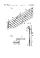
- FIG. 1 shows a side view of a sectional door according to the present invention.
- FIG. 2 shows an exploded view of a single door section or slat assembly according to the present invention.
- FIG. 3 shows a perspective view of a sectional door of the present invention.
- FIG. 4 shows a side view of an insulation cover according to the present invention.
- FIG. 5 shows a side view illustrating the track assembly used for the present invention.
- FIG. 6 shows in cross-sectional view the guide track used for the present invention and a door section according to the present invention.
- FIG. 1 there is shown a side view of a door 10 according to the present invention.
- the door 10 comprises first, second, and third slat assemblies 12, 112, and 212. It will be readily appreciated that in actual practice a door according to the present invention will usually have more than three slat assemblies.
- Slat assembly 12 includes a slat 14, preferably made of steel although aluminum or other weather resistant metals may also be used.
- Slat 14 includes a generally planar side portion 16S, an upper plane portion 16UP perpendicular to the side portion 16S, an upper end curved portion 16UC, a lower end plane portion 16LP perpendicular to side portion 16S, and a lower end curved portion 16LC.
- slat As used throughout this application, generally planar shall be interpreted to mean that the side portion 16S (or other portion so described) defines a plane which might include decorative ridges, moulding, or other slight variations from a plane.
- the slat as shown is slat No. 14 sold by the Kinnear Division of Harsco Corporation, assignee of the present invention, and is described at page 5 of Kinnear bulletin No. 219, "Rolling doors and grills", hereby incorporated by reference.
- Slat assembly 12 further includes an extruded insulation cover 18 preferably made of rigid polyvinylchloride (PVC).
- Insulation cover piece 18 includes a generally planar side portion 20S and, separated from side portion 20S by an upper planar portion 20UP, is an upper end curved portion 20UC disposed at least partially around the upper end curved portion 16UC of the slat 14.
- Insulation cover piece 18 further includes a generally planar upper end transverse portion 20UT extending perpendicularly from the side portion 20S to the side portion 16S of the slat 14 and a generally planar lower end transverse portion extending perpendicularly from the side portion 20S to side portion 16S of the slat 14.
- the side portion 20S is parallel to side portion 16S of slat 14.
- upper curved portion 20UC and upper transverse portion 20UT of insulation cover 18 accommodate upper curved portion 16UC and upper planar portion 16UP of slat 14 in the manner shown, the insulation cover 18 will be strongly secured to slat 14. Lower transverse portion 20LT will likewise help insulation cover 18 resist being accidentally pulled off slat 14.
- Insulation 22 which may be expanded polystyrene foam, fiberglass or urethane foamed in place, is disposed in the cavity between the side portion 16S of slat 14 and the side portion 20S of the insulation cover 18.
- the cavity having insulation 22 is further bounded by the upper transverse portion 20UT and the lower transverse portion 20LT.
- the upper and lower curved portions 16UC and 16LC of slat 14 and upper curved portion 20UC are disposed vertically in line with the insulation containing cavity.
- Vertically in line refers to above and below the cavity when the slat assembly 12 is disposed in a vertical position as when door 10 is closed.
- Adhesive 26 is used to secure a clip 24A, preferably made of steel or other metal, to the interior surface of side portion of 16S of slat 14.
- side portion 16S has an interior surface facing towards insulation 22 and an exterior surface facing away from the insulation.
- the clip 24A will hold the insulation cover 18 to the slat 14 by reason of the upper and lower lip 20UL and 20LL respectively extending perpendicularly at the ends of upper and lower transverse portion 20UT and 20LT. As shown in FIG. 1, the clip is trapped behind the lips 20UL and 20LL.
- FIG. 4 shows a side view of the insulation cover 18 of the present invention
- the details of the extruded PVC insulation cover 18 will be discussed.
- no adhesion bonds are made between the insulation 22 and the interior surface of side portion 16S of slat 14. Instead, the insulation 22 is compressed fit and steel clip 24A is used to hold the cover 18 to the slat 14.
- Lips 20UL and 20LL on the insulation cover 18 include upper and lower nibs 20UN and 20LN such that steel clip 24 may move relative to the upper and lower lips 20UL and 20LL to minimize stress caused by the differing coefficients of thermal expansion of the insulation 22, PVC insulation cover 18, and steel slat 14.
- Flange 20F may extend below side portion 20S at an angle of 10° (FIG. 4) or may simply be planar with 20S (FIGS. 1 and 2). In either case, flange 20F may function as a stop to prevent slat assembly 12 from being rotated too far clockwise (FIG. 1) relative to slat assembly 112. Lower planar portion 16LP and upper planar portion 16UP will serve as stops to prevent counterclockwise rotation (FIG. 1) of one slat assembly relative to another.
- steel clip 24A is preferably one of a number of steel clips including also 24B and 24C which may be placed along the width of the slat assemblies such as 12. This will secure the insulation cover 18 to the slat 14 at various points along the length.
- the center clip 24B shown with the insulation cover 18 and insulation 22 broken away in FIG. 3, adhered to the upper and/or lower lips 20UL and 20LL as well as being adhered to the interior surface of side portion of slat 14.
- the insulation cover 18 may flex relative to the slat 14 as when the insulation expands all along the length of the interface except at center clip 24B.
- every other slat assembly may include an end lock 28 which may be used to secure the door 10 to a guide track 30.
- each slat assembly 12 could include an end lock 28 at both ends.
- no end locks 28 are shown at the left side of FIG. 3, although in actual practice the end locks would be disposed at both ends of the door 10.
- FIG. 6 shows a cross-sectional view looking directly down towards a wall 32 with a guide track 30 mounted thereupon.
- the end lock 28 which may be riveted to slat 14 cooperates with guide track 30 in a manner well known in the art. As shown in FIG.
- the door 10 may move up guide track 30 to a coiled position around core 34 by manual operation of chain 36 or, alternately, by using a motor (not shown) to drive core 34.
- the details of the guide track 30, core 34, and chain 36 need not be discussed in detail, it being noted that these features are well known in the art.
- the details of door 10 are, of course, not visible in FIG. 5.
- the structure of applicant's invention allows one to use these heretofore known components for an insulated door without requiring any adaptions to the guide track, core, and associated parts.
- the portions 20UT and 20LT of insulation cover 18 are spread apart such that lips 20UL and 20LL may be cleared by insulation 22 which is inserted from the back (e.g. opposite side 20S) into the cavity bounded by side portion 20S, upper transverse portion 20UT, lower transverse portion 20UL, upper lip 20UL, and lower lip 20LL.
- the insulation cover 18 is preferably an extrusion of PVC and is sufficiently flexible to allow this spreading.
- the steel clips 24A, 24B, and 24C are likewise inserted by spreading portions 20UT and 20LT and lips 20UL and 20LL.
- the insulation 22 and steel clips 24A, 24B, and 24C are compression fit into the cavity.
- adhesive 26 which is preferably a thermoplastic synthetic rubber base double-sided adhesive sheet or tape, is mounted to the steel clips. If the center clip 24B is to be bound to insulation cover 18, the adhesive tape 26 may be placed vertically on the center clip 24B to adhere to lips 20UL and 20LL upon insertion of the clip 24B into the insulation cover 18.
- the insulation cover 18, insulation 22, adhesive 26, and steel clips 24A, 24B and 24C together comprise an insulation cover assembly.
- Release paper (not shown) may be used on the adhesive tape 26 to keep it from bonding prior to its bonding to slat 14.
- the insulation cover assembly may be snapped onto the slat 14 with portion 20UC of insulation cover 18 pushed over and snapped to curved portion 16UC. As shown in FIG. 1, the curvature of curved portion 20UC will hold it around the slat curved portion 16UC once it is snapped into place. This may be done from the interior surface of side portion 16S of slat 14 without removing the slat 14 from track 30. The insulation cover assembly may be slid sideways until properly placed horizontally in the slat 14.
- Insulation cover 18 and assembly may then be rotated up (20UC rotating about 16UC whereupon the release paper (not shown) may be removed from the adhesive tape 26 and the insulation cover assembly pushed towards the slat 14 to complete the assembly by bonding clips 24A, 24B, and 24C to slat 14.
Landscapes
- Engineering & Computer Science (AREA)
- Structural Engineering (AREA)
- Civil Engineering (AREA)
- Architecture (AREA)
- Special Wing (AREA)
- Operating, Guiding And Securing Of Roll- Type Closing Members (AREA)
Abstract
Description
Claims (17)
Priority Applications (3)
| Application Number | Priority Date | Filing Date | Title |
|---|---|---|---|
| US06/333,805 US4436136A (en) | 1981-12-23 | 1981-12-23 | Insulated slat |
| CA000410247A CA1237651A (en) | 1981-12-23 | 1982-08-26 | Insulated sectional door |
| CA000548943A CA1244339A (en) | 1981-12-23 | 1987-10-08 | Insulated slat |
Applications Claiming Priority (1)
| Application Number | Priority Date | Filing Date | Title |
|---|---|---|---|
| US06/333,805 US4436136A (en) | 1981-12-23 | 1981-12-23 | Insulated slat |
Publications (1)
| Publication Number | Publication Date |
|---|---|
| US4436136A true US4436136A (en) | 1984-03-13 |
Family
ID=23304331
Family Applications (1)
| Application Number | Title | Priority Date | Filing Date |
|---|---|---|---|
| US06/333,805 Expired - Fee Related US4436136A (en) | 1981-12-23 | 1981-12-23 | Insulated slat |
Country Status (2)
| Country | Link |
|---|---|
| US (1) | US4436136A (en) |
| CA (1) | CA1237651A (en) |
Cited By (37)
| Publication number | Priority date | Publication date | Assignee | Title |
|---|---|---|---|---|
| US4574861A (en) * | 1983-10-11 | 1986-03-11 | Internorth, Inc. | Thermal shade |
| US4628982A (en) * | 1983-05-02 | 1986-12-16 | Martinray Industries Ltd. | Insulated closure panel |
| US4630664A (en) * | 1984-03-28 | 1986-12-23 | Sebastian Magro | Insulated roll-up door |
| US4690193A (en) * | 1985-08-07 | 1987-09-01 | The Standard Oil Company | Rolling shutter construction |
| US4718472A (en) * | 1984-07-11 | 1988-01-12 | Hormann Kg Amshausen | Sectional strip for roll-up, fold-up, and similar gates |
| US4723588A (en) * | 1984-07-05 | 1988-02-09 | Rueppel Kurt | Roller shutter slat of the so-called mini-size made from a roll-shaped aluminium strip |
| US4818590A (en) * | 1987-06-22 | 1989-04-04 | Princewood | Wood veneer covered structural rigid plastic foam elements |
| US4967509A (en) * | 1990-01-05 | 1990-11-06 | Storey Leonard M | Security window shutter |
| US4972894A (en) * | 1987-09-12 | 1990-11-27 | Rolf Machill | Roller curtain |
| US4979553A (en) * | 1989-02-10 | 1990-12-25 | Wayne-Dalton Corporation | Slat assembly and curtain for rolling door |
| EP0405675A1 (en) * | 1989-06-30 | 1991-01-02 | Hallington B.V. | Interlockable building panel and sectional door consisting of interlockable building panels |
| US5117893A (en) * | 1985-08-07 | 1992-06-02 | Excel Shutter Systems, Inc. | Rolling shutter system |
| EP0516961A1 (en) * | 1991-05-31 | 1992-12-09 | Link 51 Limited | Door and locker assembly comprising a door |
| US5419386A (en) * | 1994-03-07 | 1995-05-30 | Magro; Sebastian | Insulated roll-up door provided with metal outer and inner walls |
| WO1997030259A1 (en) * | 1996-02-13 | 1997-08-21 | Hörmann KG Brockhagen | Insulation device for gate members of sectional gates |
| FR2745845A1 (en) * | 1996-03-08 | 1997-09-12 | Liperini Martine | Roller shutter vane |
| US5921307A (en) * | 1997-12-01 | 1999-07-13 | Garage Door Group, Inc. | Garage door hinge |
| US5941021A (en) * | 1996-11-06 | 1999-08-24 | Vassallo Research & Development Corporation | Louver-type window and slat therefor |
| US6041843A (en) * | 1998-03-24 | 2000-03-28 | Wayne-Dalton Corp. | Collapsible cascading impact-resistant door |
| US6076590A (en) * | 1997-12-01 | 2000-06-20 | Garage Door Group, Inc. | Segmented garage door and hinges |
| US6148896A (en) * | 1998-05-22 | 2000-11-21 | Pinto; Joseph | Method and apparatus for overlaying a garage door |
| US6672362B1 (en) | 2000-11-10 | 2004-01-06 | Wayne-Dalton Corp. | Upward acting sectional door |
| EP1359278A3 (en) * | 2002-04-17 | 2004-01-21 | Wayne-Dalton Corp. | Insulated sectional door and method of construction |
| WO2004072288A1 (en) * | 2003-02-17 | 2004-08-26 | Heydebreck Gmbh | Fireproof roller shutters and method for producing a fireproof roller shutter |
| WO2005105218A1 (en) * | 2004-04-28 | 2005-11-10 | Jansen Entwicklungs Gmbh & Co. Kg. | Fire door |
| US20060272784A1 (en) * | 2005-05-12 | 2006-12-07 | Ronald Huneycutt | Reinforced garage door |
| US20070151169A1 (en) * | 2005-12-21 | 2007-07-05 | American Standard International Inc | Thermal break and panel joint for an air handling enclosure |
| US20090199501A1 (en) * | 2008-02-07 | 2009-08-13 | O'riordan Brian P | Garage Door Insulation System |
| US20120085031A1 (en) * | 2010-10-12 | 2012-04-12 | Gracious Living Innovations, Inc. | Window covering for an architectural opening |
| US20160076301A1 (en) * | 2014-09-11 | 2016-03-17 | Hörmann Kg Dissen | Rolling shutter with damping body |
| US20160116184A1 (en) * | 2014-10-28 | 2016-04-28 | T.A. Morrison & Company, Inc. | Damper with integrated blade stop |
| US10066434B2 (en) | 2011-08-15 | 2018-09-04 | Cold Chain, Llc | Insulated overhead door |
| US20190390511A1 (en) * | 2018-06-22 | 2019-12-26 | Mckeon Rolling Steel Door Co., Inc. | Slatted Door with Increased Impact Resistance |
| DE102019111534A1 (en) | 2019-01-14 | 2020-07-16 | Hörmann KG Amshausen | Roller shutter slat, roller shutter curtain and roller shutter |
| EP3683396A1 (en) | 2019-01-14 | 2020-07-22 | Hörmann Kg Amshausen | Roller gate flap, roller gate curtain and roller gate |
| US11230880B2 (en) | 2018-04-03 | 2022-01-25 | Alpine Overhead Doors, Inc. | Unitary extruded shell for assembling non-insulated and insulated slats for rolling doors and method of forming same |
| US12129708B2 (en) | 2021-06-15 | 2024-10-29 | Mckeon Rolling Steel Door Co., Inc. | Slatted door with increased impact resistance |
Citations (17)
| Publication number | Priority date | Publication date | Assignee | Title |
|---|---|---|---|---|
| US546858A (en) | 1895-09-24 | Rolling fireproof blind or partition | ||
| US675953A (en) | 1900-10-20 | 1901-06-11 | William Raymond Kinnear | Fireproof blind. |
| US675954A (en) | 1900-10-20 | 1901-06-11 | William Raymond Kinnear | Fireproof blind. |
| US1013945A (en) | 1908-01-27 | 1912-01-09 | Edward H Mccloud | Flexible fire-resisting shutter. |
| US1352656A (en) | 1919-11-25 | 1920-09-14 | Cahill John | Flexible curtain |
| US1707287A (en) | 1926-08-30 | 1929-04-02 | Sudzki Tomitaro | Fireproof shutter |
| US2039447A (en) | 1931-11-06 | 1936-05-05 | Milton A Pixley | Closure |
| US3481386A (en) | 1966-06-15 | 1969-12-02 | Continental Gummi Werke Ag | Pneumatic vehicle tire |
| US3511301A (en) | 1967-10-26 | 1970-05-12 | Graham Door Co | Door sections having unitized hardware |
| US3772129A (en) | 1970-02-09 | 1973-11-13 | Dover Shutters Ltd | Laths for roller shutters |
| DE2109838C3 (en) | 1971-03-02 | 1973-11-15 | Braselmann Geb. Jaeger, Elisabeth, 5805 Breckerfeld | Translucent armor for roller doors or the like |
| US3941180A (en) | 1974-12-30 | 1976-03-02 | Winnebago Industries, Inc. | Sectional door and guard rail assembly |
| US4037639A (en) | 1976-11-08 | 1977-07-26 | Jones J Paul | Thermal barrier |
| US4183393A (en) | 1978-03-27 | 1980-01-15 | Overhead Door Corporation | Heat insulated door |
| DE2912774A1 (en) | 1979-03-30 | 1980-10-02 | Braselmann Klaus | Roller shutter hinged slat insulating layer - is sited on inside between protruding interlocking edges, in protected position |
| DE2925635A1 (en) | 1979-06-26 | 1981-01-15 | Rolf Machill | Roller shutter bar assembly of metal and PVC - has polyurethane foam filling and ensures improved heat insulation |
| DE2808177C2 (en) | 1978-02-25 | 1983-04-21 | Th. Kauffmann KG-GmbH & Co Rolladen-Kauffmann, 5000 Köln | Roller shutter slat |
-
1981
- 1981-12-23 US US06/333,805 patent/US4436136A/en not_active Expired - Fee Related
-
1982
- 1982-08-26 CA CA000410247A patent/CA1237651A/en not_active Expired
Patent Citations (17)
| Publication number | Priority date | Publication date | Assignee | Title |
|---|---|---|---|---|
| US546858A (en) | 1895-09-24 | Rolling fireproof blind or partition | ||
| US675953A (en) | 1900-10-20 | 1901-06-11 | William Raymond Kinnear | Fireproof blind. |
| US675954A (en) | 1900-10-20 | 1901-06-11 | William Raymond Kinnear | Fireproof blind. |
| US1013945A (en) | 1908-01-27 | 1912-01-09 | Edward H Mccloud | Flexible fire-resisting shutter. |
| US1352656A (en) | 1919-11-25 | 1920-09-14 | Cahill John | Flexible curtain |
| US1707287A (en) | 1926-08-30 | 1929-04-02 | Sudzki Tomitaro | Fireproof shutter |
| US2039447A (en) | 1931-11-06 | 1936-05-05 | Milton A Pixley | Closure |
| US3481386A (en) | 1966-06-15 | 1969-12-02 | Continental Gummi Werke Ag | Pneumatic vehicle tire |
| US3511301A (en) | 1967-10-26 | 1970-05-12 | Graham Door Co | Door sections having unitized hardware |
| US3772129A (en) | 1970-02-09 | 1973-11-13 | Dover Shutters Ltd | Laths for roller shutters |
| DE2109838C3 (en) | 1971-03-02 | 1973-11-15 | Braselmann Geb. Jaeger, Elisabeth, 5805 Breckerfeld | Translucent armor for roller doors or the like |
| US3941180A (en) | 1974-12-30 | 1976-03-02 | Winnebago Industries, Inc. | Sectional door and guard rail assembly |
| US4037639A (en) | 1976-11-08 | 1977-07-26 | Jones J Paul | Thermal barrier |
| DE2808177C2 (en) | 1978-02-25 | 1983-04-21 | Th. Kauffmann KG-GmbH & Co Rolladen-Kauffmann, 5000 Köln | Roller shutter slat |
| US4183393A (en) | 1978-03-27 | 1980-01-15 | Overhead Door Corporation | Heat insulated door |
| DE2912774A1 (en) | 1979-03-30 | 1980-10-02 | Braselmann Klaus | Roller shutter hinged slat insulating layer - is sited on inside between protruding interlocking edges, in protected position |
| DE2925635A1 (en) | 1979-06-26 | 1981-01-15 | Rolf Machill | Roller shutter bar assembly of metal and PVC - has polyurethane foam filling and ensures improved heat insulation |
Non-Patent Citations (1)
| Title |
|---|
| Kinnear Bulletin No. 219, Kinnear Rolling Doors and Grilles, pp. 4, 5 and 9. |
Cited By (48)
| Publication number | Priority date | Publication date | Assignee | Title |
|---|---|---|---|---|
| US4628982A (en) * | 1983-05-02 | 1986-12-16 | Martinray Industries Ltd. | Insulated closure panel |
| US4574861A (en) * | 1983-10-11 | 1986-03-11 | Internorth, Inc. | Thermal shade |
| US4630664A (en) * | 1984-03-28 | 1986-12-23 | Sebastian Magro | Insulated roll-up door |
| US4723588A (en) * | 1984-07-05 | 1988-02-09 | Rueppel Kurt | Roller shutter slat of the so-called mini-size made from a roll-shaped aluminium strip |
| US4718472A (en) * | 1984-07-11 | 1988-01-12 | Hormann Kg Amshausen | Sectional strip for roll-up, fold-up, and similar gates |
| US4690193A (en) * | 1985-08-07 | 1987-09-01 | The Standard Oil Company | Rolling shutter construction |
| US5117893A (en) * | 1985-08-07 | 1992-06-02 | Excel Shutter Systems, Inc. | Rolling shutter system |
| US4818590A (en) * | 1987-06-22 | 1989-04-04 | Princewood | Wood veneer covered structural rigid plastic foam elements |
| US4972894A (en) * | 1987-09-12 | 1990-11-27 | Rolf Machill | Roller curtain |
| US4979553A (en) * | 1989-02-10 | 1990-12-25 | Wayne-Dalton Corporation | Slat assembly and curtain for rolling door |
| EP0405675A1 (en) * | 1989-06-30 | 1991-01-02 | Hallington B.V. | Interlockable building panel and sectional door consisting of interlockable building panels |
| WO1992007158A1 (en) * | 1990-01-05 | 1992-04-30 | Buckeye-Western, Inc. | Security window shutter |
| US4967509A (en) * | 1990-01-05 | 1990-11-06 | Storey Leonard M | Security window shutter |
| EP0516961A1 (en) * | 1991-05-31 | 1992-12-09 | Link 51 Limited | Door and locker assembly comprising a door |
| US5419386A (en) * | 1994-03-07 | 1995-05-30 | Magro; Sebastian | Insulated roll-up door provided with metal outer and inner walls |
| WO1997030259A1 (en) * | 1996-02-13 | 1997-08-21 | Hörmann KG Brockhagen | Insulation device for gate members of sectional gates |
| FR2745845A1 (en) * | 1996-03-08 | 1997-09-12 | Liperini Martine | Roller shutter vane |
| US5941021A (en) * | 1996-11-06 | 1999-08-24 | Vassallo Research & Development Corporation | Louver-type window and slat therefor |
| US5921307A (en) * | 1997-12-01 | 1999-07-13 | Garage Door Group, Inc. | Garage door hinge |
| US6076590A (en) * | 1997-12-01 | 2000-06-20 | Garage Door Group, Inc. | Segmented garage door and hinges |
| US6041843A (en) * | 1998-03-24 | 2000-03-28 | Wayne-Dalton Corp. | Collapsible cascading impact-resistant door |
| US6148896A (en) * | 1998-05-22 | 2000-11-21 | Pinto; Joseph | Method and apparatus for overlaying a garage door |
| US20040099382A1 (en) * | 2000-11-10 | 2004-05-27 | Wayne-Dalton Corp. | Upward acting sectional door |
| US6672362B1 (en) | 2000-11-10 | 2004-01-06 | Wayne-Dalton Corp. | Upward acting sectional door |
| US6955206B2 (en) | 2000-11-10 | 2005-10-18 | Wayne-Dalton Corp | Upward acting sectional door |
| EP1359278A3 (en) * | 2002-04-17 | 2004-01-21 | Wayne-Dalton Corp. | Insulated sectional door and method of construction |
| WO2004072288A1 (en) * | 2003-02-17 | 2004-08-26 | Heydebreck Gmbh | Fireproof roller shutters and method for producing a fireproof roller shutter |
| WO2005105218A1 (en) * | 2004-04-28 | 2005-11-10 | Jansen Entwicklungs Gmbh & Co. Kg. | Fire door |
| US20060272784A1 (en) * | 2005-05-12 | 2006-12-07 | Ronald Huneycutt | Reinforced garage door |
| US20070151169A1 (en) * | 2005-12-21 | 2007-07-05 | American Standard International Inc | Thermal break and panel joint for an air handling enclosure |
| US7526903B2 (en) * | 2005-12-21 | 2009-05-05 | Trane International Inc. | Thermal break and panel joint for an air handling enclosure |
| US8851145B2 (en) | 2008-02-07 | 2014-10-07 | Owens Corning Intellecutal Capital, LLC | Garage door insulation system |
| US8590244B2 (en) | 2008-02-07 | 2013-11-26 | Owens Corning Intellectual Capital, Llc | Garage door insulation system |
| US20090199501A1 (en) * | 2008-02-07 | 2009-08-13 | O'riordan Brian P | Garage Door Insulation System |
| US8413706B2 (en) * | 2010-10-12 | 2013-04-09 | Gracious Living Innovations, Inc. | Window covering for an architectural opening |
| US20120085031A1 (en) * | 2010-10-12 | 2012-04-12 | Gracious Living Innovations, Inc. | Window covering for an architectural opening |
| US10066434B2 (en) | 2011-08-15 | 2018-09-04 | Cold Chain, Llc | Insulated overhead door |
| US20160076301A1 (en) * | 2014-09-11 | 2016-03-17 | Hörmann Kg Dissen | Rolling shutter with damping body |
| US9644421B2 (en) * | 2014-09-11 | 2017-05-09 | Hormann Kg Dissen | Rolling shutter with damping body |
| US10222089B2 (en) * | 2014-10-28 | 2019-03-05 | T.A. Morrison & Co. Inc. | Damper with integrated blade stop |
| US20160116184A1 (en) * | 2014-10-28 | 2016-04-28 | T.A. Morrison & Company, Inc. | Damper with integrated blade stop |
| US11230880B2 (en) | 2018-04-03 | 2022-01-25 | Alpine Overhead Doors, Inc. | Unitary extruded shell for assembling non-insulated and insulated slats for rolling doors and method of forming same |
| US20190390511A1 (en) * | 2018-06-22 | 2019-12-26 | Mckeon Rolling Steel Door Co., Inc. | Slatted Door with Increased Impact Resistance |
| US10794112B2 (en) * | 2018-06-22 | 2020-10-06 | Mckeon Rolling Steel Door Co., Inc. | Slatted door with increased impact resistance |
| US11566467B2 (en) | 2018-06-22 | 2023-01-31 | Mckeon Rolling Steel Door Co., Inc. | Slatted door with increased impact resistance |
| DE102019111534A1 (en) | 2019-01-14 | 2020-07-16 | Hörmann KG Amshausen | Roller shutter slat, roller shutter curtain and roller shutter |
| EP3683396A1 (en) | 2019-01-14 | 2020-07-22 | Hörmann Kg Amshausen | Roller gate flap, roller gate curtain and roller gate |
| US12129708B2 (en) | 2021-06-15 | 2024-10-29 | Mckeon Rolling Steel Door Co., Inc. | Slatted door with increased impact resistance |
Also Published As
| Publication number | Publication date |
|---|---|
| CA1237651A (en) | 1988-06-07 |
Similar Documents
| Publication | Publication Date | Title |
|---|---|---|
| US4436136A (en) | Insulated slat | |
| US4467853A (en) | Door with guide insulation and weatherstripping | |
| EP0092257B1 (en) | Removable window insulation system | |
| US4409758A (en) | Perimeter strip for magnetically attractable extruded plastic window system | |
| EP1123450B1 (en) | Glazing support systems | |
| US4458459A (en) | Sectional molding for surrounding a pane of glass sealed in the window opening of a vehicle, or the like | |
| US4570399A (en) | Panel lite insert system | |
| EP3911815A1 (en) | Frame solution with gasket abutting vig unit surface | |
| US4185416A (en) | Weatherstrip | |
| US8851145B2 (en) | Garage door insulation system | |
| USRE32509E (en) | Insulating storm window attachment | |
| EP1359278A2 (en) | Insulated sectional door and method of construction | |
| EP0004459B1 (en) | Improved means for joining panels | |
| US5282338A (en) | Sealing structure | |
| US4586306A (en) | Window assembly and grille retaining strip hardware therefor | |
| CA1244339A (en) | Insulated slat | |
| US4807396A (en) | Sealing assembly | |
| GB2311799A (en) | Sealing and guiding strip for the sharp corner of a vehicle window | |
| US7347155B2 (en) | Sliding window arrangement | |
| WO1996018778A1 (en) | A device in a profile-member system | |
| JPS5889415A (en) | Seal strip | |
| US5356694A (en) | Extruded connector strip | |
| EP0367625A1 (en) | Improvements in and relating to shutter laths | |
| AU2002224228B2 (en) | A retainer member for retaining a pane panel within a frame | |
| EP0011901A1 (en) | Fixation section and door, window or frame provided with such section |
Legal Events
| Date | Code | Title | Description |
|---|---|---|---|
| AS | Assignment |
Owner name: HARSCO CORPORATION, CAMP HILL, PA A CORP. OF DE Free format text: ASSIGNMENT OF ASSIGNORS INTEREST.;ASSIGNOR:DOWNEY, ROBERT C. JR.;REEL/FRAME:003970/0685 Effective date: 19811209 |
|
| MAFP | Maintenance fee payment |
Free format text: PAYMENT OF MAINTENANCE FEE, 4TH YEAR, PL 96-517 (ORIGINAL EVENT CODE: M170); ENTITY STATUS OF PATENT OWNER: LARGE ENTITY Year of fee payment: 4 |
|
| FEPP | Fee payment procedure |
Free format text: PAYOR NUMBER ASSIGNED (ORIGINAL EVENT CODE: ASPN); ENTITY STATUS OF PATENT OWNER: LARGE ENTITY |
|
| AS | Assignment |
Owner name: WAYNE-DALTON CORP., OHIO Free format text: ASSIGNMENT OF ASSIGNORS INTEREST.;ASSIGNOR:HARSCO CORPORATION, A CORP. OF DE.;REEL/FRAME:005422/0860 Effective date: 19900402 |
|
| MAFP | Maintenance fee payment |
Free format text: PAYMENT OF MAINTENANCE FEE, 8TH YEAR, PL 96-517 (ORIGINAL EVENT CODE: M171); ENTITY STATUS OF PATENT OWNER: LARGE ENTITY Year of fee payment: 8 |
|
| FEPP | Fee payment procedure |
Free format text: MAINTENANCE FEE REMINDER MAILED (ORIGINAL EVENT CODE: REM.); ENTITY STATUS OF PATENT OWNER: LARGE ENTITY |
|
| LAPS | Lapse for failure to pay maintenance fees | ||
| FP | Lapsed due to failure to pay maintenance fee |
Effective date: 19960313 |
|
| STCH | Information on status: patent discontinuation |
Free format text: PATENT EXPIRED DUE TO NONPAYMENT OF MAINTENANCE FEES UNDER 37 CFR 1.362 |