US4427242A - Unitized tapered roller bearing - Google Patents
Unitized tapered roller bearing Download PDFInfo
- Publication number
- US4427242A US4427242A US06/342,826 US34282682A US4427242A US 4427242 A US4427242 A US 4427242A US 34282682 A US34282682 A US 34282682A US 4427242 A US4427242 A US 4427242A
- Authority
- US
- United States
- Prior art keywords
- cage
- cup
- cone
- raceway
- end ring
- Prior art date
- Legal status (The legal status is an assumption and is not a legal conclusion. Google has not performed a legal analysis and makes no representation as to the accuracy of the status listed.)
- Expired - Lifetime
Links
- 238000005096 rolling process Methods 0.000 claims description 22
- 239000002184 metal Substances 0.000 claims description 5
- 238000007789 sealing Methods 0.000 claims description 4
- 239000000463 material Substances 0.000 claims description 3
- 238000009434 installation Methods 0.000 abstract description 3
- 229920000642 polymer Polymers 0.000 description 7
- 239000000428 dust Substances 0.000 description 4
- 230000000712 assembly Effects 0.000 description 3
- 238000000429 assembly Methods 0.000 description 3
- 230000000295 complement effect Effects 0.000 description 3
- 238000010276 construction Methods 0.000 description 3
- 229920001971 elastomer Polymers 0.000 description 3
- 239000000806 elastomer Substances 0.000 description 3
- 239000000314 lubricant Substances 0.000 description 3
- 229910000831 Steel Inorganic materials 0.000 description 2
- 239000000356 contaminant Substances 0.000 description 2
- 238000000034 method Methods 0.000 description 2
- 230000036316 preload Effects 0.000 description 2
- 239000010959 steel Substances 0.000 description 2
- 230000000694 effects Effects 0.000 description 1
- 230000001050 lubricating effect Effects 0.000 description 1
- 238000012423 maintenance Methods 0.000 description 1
- 238000012986 modification Methods 0.000 description 1
- 230000004048 modification Effects 0.000 description 1
- 238000000465 moulding Methods 0.000 description 1
- 239000000126 substance Substances 0.000 description 1
- XLYOFNOQVPJJNP-UHFFFAOYSA-N water Substances O XLYOFNOQVPJJNP-UHFFFAOYSA-N 0.000 description 1
Images

Classifications
-
- F—MECHANICAL ENGINEERING; LIGHTING; HEATING; WEAPONS; BLASTING
- F16—ENGINEERING ELEMENTS AND UNITS; GENERAL MEASURES FOR PRODUCING AND MAINTAINING EFFECTIVE FUNCTIONING OF MACHINES OR INSTALLATIONS; THERMAL INSULATION IN GENERAL
- F16C—SHAFTS; FLEXIBLE SHAFTS; ELEMENTS OR CRANKSHAFT MECHANISMS; ROTARY BODIES OTHER THAN GEARING ELEMENTS; BEARINGS
- F16C33/00—Parts of bearings; Special methods for making bearings or parts thereof
- F16C33/30—Parts of ball or roller bearings
- F16C33/46—Cages for rollers or needles
- F16C33/4605—Details of interaction of cage and race, e.g. retention or centring
-
- B—PERFORMING OPERATIONS; TRANSPORTING
- B60—VEHICLES IN GENERAL
- B60B—VEHICLE WHEELS; CASTORS; AXLES FOR WHEELS OR CASTORS; INCREASING WHEEL ADHESION
- B60B27/00—Hubs
- B60B27/001—Hubs with roller-bearings
-
- F—MECHANICAL ENGINEERING; LIGHTING; HEATING; WEAPONS; BLASTING
- F16—ENGINEERING ELEMENTS AND UNITS; GENERAL MEASURES FOR PRODUCING AND MAINTAINING EFFECTIVE FUNCTIONING OF MACHINES OR INSTALLATIONS; THERMAL INSULATION IN GENERAL
- F16C—SHAFTS; FLEXIBLE SHAFTS; ELEMENTS OR CRANKSHAFT MECHANISMS; ROTARY BODIES OTHER THAN GEARING ELEMENTS; BEARINGS
- F16C19/00—Bearings with rolling contact, for exclusively rotary movement
- F16C19/22—Bearings with rolling contact, for exclusively rotary movement with bearing rollers essentially of the same size in one or more circular rows, e.g. needle bearings
- F16C19/34—Bearings with rolling contact, for exclusively rotary movement with bearing rollers essentially of the same size in one or more circular rows, e.g. needle bearings for both radial and axial load
- F16C19/38—Bearings with rolling contact, for exclusively rotary movement with bearing rollers essentially of the same size in one or more circular rows, e.g. needle bearings for both radial and axial load with two or more rows of rollers
- F16C19/383—Bearings with rolling contact, for exclusively rotary movement with bearing rollers essentially of the same size in one or more circular rows, e.g. needle bearings for both radial and axial load with two or more rows of rollers with tapered rollers, i.e. rollers having essentially the shape of a truncated cone
- F16C19/385—Bearings with rolling contact, for exclusively rotary movement with bearing rollers essentially of the same size in one or more circular rows, e.g. needle bearings for both radial and axial load with two or more rows of rollers with tapered rollers, i.e. rollers having essentially the shape of a truncated cone with two rows, i.e. double-row tapered roller bearings
- F16C19/386—Bearings with rolling contact, for exclusively rotary movement with bearing rollers essentially of the same size in one or more circular rows, e.g. needle bearings for both radial and axial load with two or more rows of rollers with tapered rollers, i.e. rollers having essentially the shape of a truncated cone with two rows, i.e. double-row tapered roller bearings in O-arrangement
-
- F—MECHANICAL ENGINEERING; LIGHTING; HEATING; WEAPONS; BLASTING
- F16—ENGINEERING ELEMENTS AND UNITS; GENERAL MEASURES FOR PRODUCING AND MAINTAINING EFFECTIVE FUNCTIONING OF MACHINES OR INSTALLATIONS; THERMAL INSULATION IN GENERAL
- F16C—SHAFTS; FLEXIBLE SHAFTS; ELEMENTS OR CRANKSHAFT MECHANISMS; ROTARY BODIES OTHER THAN GEARING ELEMENTS; BEARINGS
- F16C33/00—Parts of bearings; Special methods for making bearings or parts thereof
- F16C33/72—Sealings
- F16C33/76—Sealings of ball or roller bearings
- F16C33/78—Sealings of ball or roller bearings with a diaphragm, disc, or ring, with or without resilient members
- F16C33/7803—Sealings of ball or roller bearings with a diaphragm, disc, or ring, with or without resilient members suited for particular types of rolling bearings
- F16C33/7813—Sealings of ball or roller bearings with a diaphragm, disc, or ring, with or without resilient members suited for particular types of rolling bearings for tapered roller bearings
-
- F—MECHANICAL ENGINEERING; LIGHTING; HEATING; WEAPONS; BLASTING
- F16—ENGINEERING ELEMENTS AND UNITS; GENERAL MEASURES FOR PRODUCING AND MAINTAINING EFFECTIVE FUNCTIONING OF MACHINES OR INSTALLATIONS; THERMAL INSULATION IN GENERAL
- F16C—SHAFTS; FLEXIBLE SHAFTS; ELEMENTS OR CRANKSHAFT MECHANISMS; ROTARY BODIES OTHER THAN GEARING ELEMENTS; BEARINGS
- F16C33/00—Parts of bearings; Special methods for making bearings or parts thereof
- F16C33/72—Sealings
- F16C33/76—Sealings of ball or roller bearings
- F16C33/78—Sealings of ball or roller bearings with a diaphragm, disc, or ring, with or without resilient members
- F16C33/7869—Sealings of ball or roller bearings with a diaphragm, disc, or ring, with or without resilient members mounted with a cylindrical portion to the inner surface of the outer race and having a radial portion extending inward
- F16C33/7873—Sealings of ball or roller bearings with a diaphragm, disc, or ring, with or without resilient members mounted with a cylindrical portion to the inner surface of the outer race and having a radial portion extending inward with a single sealing ring of generally L-shaped cross-section
- F16C33/7876—Sealings of ball or roller bearings with a diaphragm, disc, or ring, with or without resilient members mounted with a cylindrical portion to the inner surface of the outer race and having a radial portion extending inward with a single sealing ring of generally L-shaped cross-section with sealing lips
-
- F—MECHANICAL ENGINEERING; LIGHTING; HEATING; WEAPONS; BLASTING
- F16—ENGINEERING ELEMENTS AND UNITS; GENERAL MEASURES FOR PRODUCING AND MAINTAINING EFFECTIVE FUNCTIONING OF MACHINES OR INSTALLATIONS; THERMAL INSULATION IN GENERAL
- F16C—SHAFTS; FLEXIBLE SHAFTS; ELEMENTS OR CRANKSHAFT MECHANISMS; ROTARY BODIES OTHER THAN GEARING ELEMENTS; BEARINGS
- F16C2240/00—Specified values or numerical ranges of parameters; Relations between them
- F16C2240/40—Linear dimensions, e.g. length, radius, thickness, gap
-
- F—MECHANICAL ENGINEERING; LIGHTING; HEATING; WEAPONS; BLASTING
- F16—ENGINEERING ELEMENTS AND UNITS; GENERAL MEASURES FOR PRODUCING AND MAINTAINING EFFECTIVE FUNCTIONING OF MACHINES OR INSTALLATIONS; THERMAL INSULATION IN GENERAL
- F16C—SHAFTS; FLEXIBLE SHAFTS; ELEMENTS OR CRANKSHAFT MECHANISMS; ROTARY BODIES OTHER THAN GEARING ELEMENTS; BEARINGS
- F16C2326/00—Articles relating to transporting
- F16C2326/01—Parts of vehicles in general
- F16C2326/02—Wheel hubs or castors
-
- F—MECHANICAL ENGINEERING; LIGHTING; HEATING; WEAPONS; BLASTING
- F16—ENGINEERING ELEMENTS AND UNITS; GENERAL MEASURES FOR PRODUCING AND MAINTAINING EFFECTIVE FUNCTIONING OF MACHINES OR INSTALLATIONS; THERMAL INSULATION IN GENERAL
- F16C—SHAFTS; FLEXIBLE SHAFTS; ELEMENTS OR CRANKSHAFT MECHANISMS; ROTARY BODIES OTHER THAN GEARING ELEMENTS; BEARINGS
- F16C33/00—Parts of bearings; Special methods for making bearings or parts thereof
- F16C33/30—Parts of ball or roller bearings
- F16C33/46—Cages for rollers or needles
- F16C33/4617—Massive or moulded cages having cage pockets surrounding the rollers, e.g. machined window cages
- F16C33/4623—Massive or moulded cages having cage pockets surrounding the rollers, e.g. machined window cages formed as one-piece cages, i.e. monoblock cages
- F16C33/4635—Massive or moulded cages having cage pockets surrounding the rollers, e.g. machined window cages formed as one-piece cages, i.e. monoblock cages made from plastic, e.g. injection moulded window cages
Definitions
- This invention relates in general to antifriction bearings and more particularly to an antifriction bearing that can withstand large parting forces in the axial direction.
- double row tapered roller bearings that are preset, sealed, and unitized are ideally suited for the front wheel assemblies of their automobiles.
- front wheel drive automobiles are generally lighter than their rear wheel drive counterparts, but most of the weight is concentrated over the front wheels--indeed significantly more than in comparable rear wheel drive automobiles.
- the double row bearing includes a double cup, that is a single cup or outer race having two raceways on it, which fits into a steering knuckle.
- the bearing also includes two cones which fit into the double cup from opposite ends and form an inner race.
- there is a single row of tapered rollers between each cone and the cup the rollers of each row being in the indirect orientation, that is with their large diameter ends presented outwardly away from the center of the bearing.
- the cones fit onto a drive flange, there being an interference fit between the cones and the drive flange to insure maximum stability.
- a powered drive axle extends through the drive flange, and a nut threads over the end of the axle to clamp the drive flange and the two cones on it together.
- One of the principle objects of the present invention is to provide a bearing that is unitized for handling purposes by a seal attached to one of its races by a press fit. Another object is to provide a bearing of the type stated that can withstand large parting forces at its inner races without being damaged. A further object is to provide a bearing of the type stated in which the parting forces are transmitted through a cage of the bearing. An additional object is to provide a bearing of the type stated in which the cage may be formed from a polymer. Still another object is to provide a bearing of the type stated in which the seal case surrounds and confines the cage when an axial stripping force is transmitted through it so as to prevent the cage from buckling.
- Yet another object is to provide a bearing of the type stated which is in the configuration of a tapered roller bearing.
- a further object is to provide a bearing of the type stated which is ideally suited for use at the front wheel locations of front wheel drive automobiles.
- the present invention is embodied in a bearing having an outer race, a row of rolling elements along the outer race, an inner race along which the rolling elements also extend, with the inner race being configured such that it will force the rolling elements in one direction if the inner race is moved in that direction, a cage for maintaining the proper spacing between the rolling elements and having an end ring that projects beyond the rolling elements in the direction that the inner race will move the rolling elements, an abutment mounted opposite the end ring, and a confining surface that will prevent the end ring and cage from buckling excessively after the end ring is forced into the abutment so that the cage will transmit the force to the abutment without breaking.
- the invention also consists in the parts and in the arrangements and combinations of parts hereinafter described and claimed.
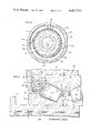
- FIG. 1 is a sectional view of a front wheel drive assembly provided with a tapered roller bearing constructed in accordance with and embodying the present invention
- FIG. 2 is an enlarged sectional view of the bearing in its normal operating condition
- FIG. 3 is a sectional view taken along line 3--3 of FIG. 2 and showing the chaplets opposite to which the cage on the cone assembly is mounted;
- FIG. 4 is an enlarged sectional view similar to FIG. 2, but showing the bearing in the condition that it assumes when the drive flange is stripped from the bearing.
- FIG. 1 designates a tapered roller bearing that is particularly suited for use as a front wheel bearing for a front wheel drive automobile. As such it fits into a bore 2 within a steering knuckle 4 and around a hollow spindle 6 on a drive flange 8, so that the drive flange 8 can rotate relative to the knuckle 4.
- the bearing B permits a wheel on the drive flange 8 to rotate relative to the knuckle 4 and transmits radial loads, as well as axial loads in both directions, from the knuckle 4 to the drive flange 8.
- the drive flange is driven by a splined axle 10 which fits into the hollow spindle 6 and the two are held together, with the bearing B clamped between them, by a nut 12 that threads over the end of the axle 10 and against the outwardly presented face of the drive flange 8.
- the drive flange 8 has a shoulder 14 located at the end of its spindle 6, while the axle 10 also has a shoulder 16.
- the two shoulders 14 and 16 face each other and are located at opposite ends of the bearing B, so that when the nut 12 is turned down, the shoulders 14 and 16 draw together and clamp the bearing B tightly between them.
- the bore 2, the drive flange 8, and the axle 10 all have a common axis X which is also the axis of rotation for the bearing B.
- retaining elements 18 which may take the form of a shoulder and clamping plate (as illustrated), snap rings, or the like.
- the bearing B basically includes (FIG. 1) an outer race in the form of a double cup 20, an inner race in the form of a pair of cones 22 located within the cup 20, rolling elements in the form of tapered rollers 24 arranged in two rows with a single row of rollers 24 surrounding each cone 22, a cage 26 for each row of rollers 24 to maintain the proper spacing between the rollers 24, and seals 28 at the ends of the cup 20 for closing the annular spaces between the ends of the cup 20 and cones 22.
- Each cone 22, its complement of rollers 24, and its cage 26, are known as a cone assembly.
- the double cup 20 fits snugly within the bore 2 of the steering knuckle 4 (FIG. 1), and indeed an interference fit exists between the two. Nevertheless the knuckle 4 is provided with the retaining elements 18 to ensure that the cup 20 remains in the bore 2.
- the cup 20 has a pair of inwardly presented raceways 30 (FIG. 2) which taper outwardly away from the center of the bearing B so that the large diameter ends of the raceways 30 are located toward the ends of the cup 20. Beyond each raceway 30 the cup 20 is provided with a cup extension 32 having a short end bore 34 that is greater in diameter than the large end of the raceway 30 and opens out of the cup 20 at a slight chamfer 35.
- the diameter of the end bores 34 is also greater than the inside diameter of the retaining elements 18 so that the elements 18 project radially inwardly past the surfaces of the bores 34.
- Each cup extension 32 is further provided with an annular groove or undercut 36 that is larger in diameter than the end bore 34 and separates the bore 34 from the adjacent raceway 30.
- the two cones 22 are pressed over the hollow spindle 6 on the drive flange 8 and are located within the double cup 20 (FIG. 1).
- Each has an outwardly presented raceway 38 (FIG. 2) that is located opposite to one of the raceways 30 of the cup 20.
- the cone raceways 38 taper downwardly toward each other, so that the large diameter ends of the raceways 38 are at the ends of the bearing B.
- Each cone 22 at the large diameter end of its raceway 38 has a thrust rib 40 and at the small diameter end has a retaining rib 42.
- the thrust rib 40 projects axially within the cup extension 32 and has a cylindrical wear surface 44 (FIG. 2) that is presented outwardly.
- each cone 22 is on its thrust rib 40, and accordingly the back face for one cone 22 abuts against the shoulder 14 of the drive flange 8, while the back face of the other cone 22 abuts against the shoulder 16 of the axle 10.
- the retaining ribs 42 for the two cones 22 project outwardly from their respective cone raceways 38 at a relatively steep angle on the order of a right angle.
- the front faces of the two cones 22 are on the retaining ribs 42 and abut midway between the ends of the cup 20.
- the tapered rollers 24 are arranged in two rows between the corresponding raceways 30 and 38 of the cup 20 and cones 22, respectively (FIG. 1). Their taper corresponds to those of the raceways 30 and 38 so that generally line contact exists between the roller side faces and the raceways 30 and 38. This taper is on apex, meaning that the conical side faces of the rollers 24 of either row, if extended to their respective apexes, would have those apexes located at a common point along the axis X of the bearing B.
- the large diameter end faces of the rollers 24 around each cone 22 abut against the thrust rib 40 for that cone, and this prevents the rollers 24 from being expelled from the spaces between the opposed raceways 30 and 38.
- the bearing B is preadjusted.
- the nut 12 merely clamps the cones 22 together, but does not control the adjustment, that is the end play or preload, in the bearing B.
- the cages 26 maintain the proper spacing between the rollers 24 of their respective rows and prevent the rollers 24 from falling away from their respective cones 22 when the cones 22 are removed from the cup 20.
- Each cone 22, its complement of rollers 24, and its cage 26, when held together by the cage 26, is known as a cone assembly.
- the cages 26 may be molded from a polymer and in general may possess the configuration of the cage disclosed in U.S. Pat. application Ser. No. 135,693 of C. W. Faigley, Jr., filed Mar. 31, 1980, now U.S. Pat. No. 4,317,601, and entitled Polymer Cage for a Tapered Roller Bearing.
- the cages 26 may also be stamped from metal, even light weight metal. In any event, because of the construction of the bearing B, they are capable of transmitting high thrust loads caused by parting forces at the cones 22.
- Each cage 26 includes a large diameter end ring 46 (FIG. 2) that encircles the thrust rib 40 for its cone 22 immediately beyond the large diameter ends of the tapered rollers 24 for that cone 22, a small diameter end ring 48 that encircles the cone retaining rib 42 immediately beyond the small ends of the rollers 24, and bridges 50 which extend between the tapered sides of the rollers 24 and are attached at their ends to the large and small end rings 46 and 48, thereby creating pockets in which the rollers 24 are confined.
- the bridges 50 for the most part lie beyond the pitch circle for the rollers 24, that is beyond the imaginary cone formed by centerlines of all of the rollers 24, and are furthermore beveled along their side faces so that they generally conform to the sides of the rollers 24 which they separate.
- the large end ring 46 has an outwardly presented surface 52 that is cylindrical and concentric to the axis X of rotation. It lies immediately inwardly from the surfaces of the end bore 34 and the undercut 36. Moreover, the end ring 46 terminates short of the back face for the cone 22, and indeed extends only about half the distance of the underlying wear surface 44 on the cone thrust rib 40.
- the cage 26 will be somewhat flexible and can be distorted radially at its end rings 46 and 48 with the application of relatively little force, assuming of course that the end rings 46 and 48 are otherwise free from confinement. Since a polymer cage 26 is flexible, it will deflect within the elastic limits of the material from which it is made, and this facilitates the installation of the rollers 24 and cage 26 over the small retaining rib 42 of the cone 22 to complete the cone assembly.
- the seals 28 (FIG. 2) close the annular spaces between the cup extensions 32 and the cone thrust rib 40 at each end of the bearing B to both retain a lubricant within the interior of the bearing B and to further exclude dust, water, and other contaminants from the enclosed region.
- the seals 28 unitize the bearing B for handling purposes in that they prevent the cones 22, or more accurately, the cone assemblies, from being withdrawn from the cup 20, even when the cones 22 are subjected to vigorous jars as might occur during shipment or immediately prior to the installation of the bearings B in the bores 2 of a steering knuckle 4.
- each seal 28 includes a seal case 54 that is fitted to the cup 20 at one end of the bearing B and a flexible seal element 56 which is bonded to the case 54 and bears against the underlying wear surface 44 on the thrust rib 40 for the cone 22 that is at that particular end of the bearing B.
- the seal case 54 possesses an L-shaped configuration, it having an axially directed wall 58 that fits into the end bore 34 of the cup 20 and a radially directed wall 60 that extends inwardly from the axial wall 58, but is narrower than the annular space between the cup 20 and cone 22, so that it does not contact the wear surface 44 of the thrust rib 42.
- the outside diameter of the axial wall 58 is slightly greater than the diameter of the end bore 34, so that an interference fit exists between the wall 58 and the bore 34, and indeed the seal case 54 is pressed into the bore 34, the chamfer 35 at the end of the bore 34 serving to initially center the axial wall 58 and guide it into the bore 34.
- the free end of the axial wall 58 is slightly reduced in thickness to facilitate its entry into the end bore 34.
- the axial wall 58 is slightly shorter in length than the combined axial dimensions of the chamfer 35, the end bore 34, and the undercut 36.
- the seal case 54 When the seal case 54 is properly installed in the bore 34, the radial wall is set slightly inwardly from the end face of the cup 20, yet the reduced free end of the axial wall 58 does not extend to the end of the undercut 36.
- the seal case 54 is preferably stamped from steel, although any substance that is reasonably rigid and will not deteriorate in the presence of lubricants will suffice.
- the flexible seal element 56 (FIG. 2) is, on the other hand, formed from an elastomer, preferably in a molding operation, and indeed is molded directly against the radial wall 60 of the seal case 54. It extends axially inwardly from the radial wall 60 and includes a sealing lip 62 and a dust lip 64, both of which bear against the cylindrical wear surface 44 of the cone thrust rib 40 for the full circumference of that surface.
- the sealing lip 62 is located closer to the rollers 24 than the dust lip 64 and prevents the bearing lubricant from escaping.
- the dust lip 64 serves primarily to exclude contaminants from entering the interior of the bearing B.
- the flexible element 56 extends axially from the radial wall 60 in the same direction as does the axial wall 58 of the seal case 54, it is spaced inwardly from the axial wall 58, so that an annular region 66 exists between the axial wall 58 and the sealing element 56.
- the large diameter end ring 46 of the cage 26 projects into this region and when the bearing is in its normal operating condition (FIG. 2), the cylindrical outer surface 52 of the large end ring 46 for the cage 26 is located quite close to the axial wall 58 of the seal case 54, there being a clearance h between the two. For a typical automotive bearing B the clearance h ranges between 0.001 and 0.010 inches.
- the large end ring 46 of the cage 26 is located close enough to the axial wall 58 of the seal case 54 to enable the axial wall 58 to confine the end ring 46 should the end ring 46 tend to deform or buckle as might occur if a thrust load, that is an axially directed force, is applied to and transmitted through the cage 26.
- the seal case 54 contains several pads or chaplets 68 (FIGS. 2 & 3) that are likewise formed from an elastomer and are bonded to the inwardly presented faces of the axial and radial walls 58 and 60 at equal intervals around the seal case 54.
- the chaplets 68 which may be formed integral with the seal element 56, project into the annular region 66 and have their end faces presented opposite to the end face of the large end ring 46 on the cage 26 (FIG. 2). Even so, during the normal operation of the bearing B, a clearance e exists between the large end ring 46 and the chaplets 68, and for a typical automotive bearing, this clearance should range between 0.005 and 0.050 inches.
- rollers 24 should the rollers 24 be thrust axially away from a seated condition with respect to the cup and cone raceways 30 and 38, as will occur if an attempt is made to withdraw the outboard cone 22 from the cup 20, the rollers 24 will drive the large end ring 46 of the cage 26 against the chaplets 68. Even so, the rollers 24 still do not contact the flexible seal element 56 for the combined thickness of the chaplets 68 and the large end ring 46 is greater than the axial extension of the seal element 56 from the radial wall 60 of the seal case 54. The force on the roller 24 may increase to the point that the cage 26 cannot withstand it without beginning to buckle at its large end ring 46.
- end ring 46 will buckle only to the extent that comes against the axial wall 58 of the seal case 54 and that amount of buckling is not enough to cause a fracture to develop in the end ring 46 or, for that matter, in the remainder of the cage 26.
- the cages 26 further hold the rollers 24 around the cones 22 to unitize the cone assemblies that are formed.
- the entire bearing B is also supplied as a unitized assembly, it being held together by the seals 28 which block the large ends of the rollers 24 and prevent the cones 22 from moving out of the cup 20.
- the bearing B may be, and indeed is, installed in the bore 2 of the steering knuckle 4 and over the hollow spindle 6 of the drive flange 8 as a unit.
- the inboard cone 22 is prevented from moving through the cup 20 by the tapered geometry of the bearing B.
- the tapered rollers 24 of the inboard row seat firmly against the tapered raceways 30 and 38 of the cup 20 and inboard cone 22, thereby preventing movement of that cone.
- the hollow spindle 6 merely slides through the inboard cone 22.
- the outboard cone 22 remains with the hollow spindle 6 as the spindle 6 is withdrawn from the knuckle 4 (FIG. 4).
- the clearance c between the small ends of the rollers 24 and the retaining rib 42 for the outboard cone 22 is eliminated and the withdrawal force is thus exerted on the rollers 24.
- the clearance e at the end of the outboard cage 26 is eliminated and the large end ring 46 of the cage 26 comes against the chaplets 68. Thereafter, the clearance b between the large ends of the rollers 24 and the end ring 46 is taken up, so that the withdrawal force is transferred through the large end ring 46 of the cage 26 to the chaplets 68.
- the force exerted on the outboard cone 22 is transmitted through the retaining rib 42 of that cone to the rollers 24 of the row that surrounds the outboard cone 22.
- the rollers 24 in turn transmit the force to the large end ring 46 of the cage 26 which in turn bears against the chaplets 68 of the outboard seal 28.
- the chaplets 68 are on the seal case 54, the axially directed force is applied to the seal case 54, and if it is strong enough to overcome the friction between the axial wall 58 of the seal case 54 and the outboard end bore 24 of the double cup 20, the outboard seal 28 will move axially through the clearance g.
- the frictional force that holds the outboard cone 22 in place may be less than that which holds the seal case 54 in place, in which case the drive flange spindle 6 will slide out of the outboard cone 22.
- the outboard cage 26 enable the drive flange 8 to be stripped from the bearing B without any damage to the bearing B, but it further prevents the hub 8, and the wheel that is on it, from separating from the bearing B if the nut 12 is removed and the vehicle, of which the steering knuckle 4, the drive flange 8 and the bearing B, form a part, is moved about.
- the geometry of the tapered roller bearing B is such that the cones 22 will be urged apart on the presence of a radial load applied to the bearing B. This derives from the fact that radial loads translate into both radial and axial components at the rollers 24, and the axial components force the cones 22 apart. Were it not for the seal cases 54, the holding force of the press-fitted cones 22, and the retaining elements 18, the bearing B could come apart under these circumstances and the drive flange 8 would leave the axle 10.
- the abutment surface for the cage end rings 46 may be on individual chaplets 68, they may be on a continuous ring or pad that is molded against the radial wall 60 of the seal case 54.
- the abutment surfaces for the end rings 46 may be merely the radial walls 60 of the seal case 54, in which case it may be desirable to form the radial wall in a stepped configuration.
- the large end ring 46 of the outboard cage 26 may be confined by a surface that is located beyond the cup of the bearing, and that surface need not be part of a seal case.
Landscapes
- Engineering & Computer Science (AREA)
- General Engineering & Computer Science (AREA)
- Mechanical Engineering (AREA)
- Rolling Contact Bearings (AREA)
Abstract
Description
a>b+Δd+e
i<f+d
Claims (7)
Priority Applications (1)
| Application Number | Priority Date | Filing Date | Title |
|---|---|---|---|
| US06/342,826 US4427242A (en) | 1982-01-26 | 1982-01-26 | Unitized tapered roller bearing |
Applications Claiming Priority (1)
| Application Number | Priority Date | Filing Date | Title |
|---|---|---|---|
| US06/342,826 US4427242A (en) | 1982-01-26 | 1982-01-26 | Unitized tapered roller bearing |
Publications (1)
| Publication Number | Publication Date |
|---|---|
| US4427242A true US4427242A (en) | 1984-01-24 |
Family
ID=23343437
Family Applications (1)
| Application Number | Title | Priority Date | Filing Date |
|---|---|---|---|
| US06/342,826 Expired - Lifetime US4427242A (en) | 1982-01-26 | 1982-01-26 | Unitized tapered roller bearing |
Country Status (1)
| Country | Link |
|---|---|
| US (1) | US4427242A (en) |
Cited By (19)
| Publication number | Priority date | Publication date | Assignee | Title |
|---|---|---|---|---|
| US4592666A (en) * | 1982-06-03 | 1986-06-03 | Forsheda Ab | Sealing device for sealing a bearing |
| US4615627A (en) * | 1984-12-05 | 1986-10-07 | Ntn-Bower | Roller bearing assembly |
| GB2219634A (en) * | 1988-05-03 | 1989-12-13 | Skf Gmbh | A seal for a bearing |
| WO1994023959A1 (en) * | 1993-04-21 | 1994-10-27 | Itt Automotive Europe Gmbh | Wheel bearing for motor vehicles |
| US5492419A (en) * | 1994-07-19 | 1996-02-20 | Ntn Corporation | Cartridge axle pinion bearing assembly |
| FR2788725A1 (en) * | 1999-01-21 | 2000-07-28 | Ntn Toyo Bearing Co Ltd | Wheel mounting for motor vehicle has inner hub and outer ring with opposing double roller races |
| US6241396B1 (en) * | 1998-01-08 | 2001-06-05 | Nsk Ltd. | Sealing device for a rolling bearing |
| EP1033504A3 (en) * | 1999-03-04 | 2001-08-16 | Skf Industrie S.P.A. | A tapered bearing unit |
| US6637943B2 (en) * | 1999-12-27 | 2003-10-28 | The Timkem Company | Hub assembly for automotive vehicles |
| EP1475548A4 (en) * | 2002-02-14 | 2007-07-25 | Nsk Ltd | Sealing device, and rolling bearing and hub unit incorporating the sealing unit |
| US20070248296A1 (en) * | 2005-09-30 | 2007-10-25 | The Boeing Company | Hub joint for transferring load from a rotating shaft to a stationary body |
| US20080267547A1 (en) * | 2007-04-30 | 2008-10-30 | Qa Bearing Technologies Ltd. | Sealed bearing |
| US20090123101A1 (en) * | 2007-11-08 | 2009-05-14 | Jtekt Corporation | Rolling bearing device |
| WO2010069701A1 (en) * | 2008-12-19 | 2010-06-24 | Schaeffler Technologies Gmbh & Co. Kg | Rolling element cage having spacer |
| CN103352920A (en) * | 2013-07-05 | 2013-10-16 | 新昌县双菱汽车轴承有限公司 | Conical roller bearing |
| US20190048927A1 (en) * | 2017-08-14 | 2019-02-14 | Nsk Ltd. | Hub unit bearing and method of assembling hub unit bearing |
| CN110030273A (en) * | 2017-12-26 | 2019-07-19 | 株式会社捷太格特 | Tapered roller bearing |
| US11279172B2 (en) * | 2017-09-05 | 2022-03-22 | Aktiebolaget Skf | Modular wheel-hub bearing unit |
| US11602953B2 (en) * | 2017-09-22 | 2023-03-14 | Saf-Holland Gmbh | Housing unit and axle assembly |
Citations (7)
| Publication number | Priority date | Publication date | Assignee | Title |
|---|---|---|---|---|
| US2622944A (en) | 1950-10-27 | 1952-12-23 | Timken Roller Bearing Co | Sealed bearing unit |
| US3425758A (en) | 1966-06-28 | 1969-02-04 | Federal Mogul Corp | Seal for bearing assembly |
| US3790238A (en) | 1971-04-19 | 1974-02-05 | Timken Co | Bearing seal assembly |
| US3975066A (en) | 1974-08-28 | 1976-08-17 | Kugelfischer Georg Schafer & Co. | Journal bearing |
| US4203635A (en) | 1978-07-24 | 1980-05-20 | The Timken Company | Wheel mounting and tapered roller bearing therefor |
| US4317601A (en) | 1980-03-31 | 1982-03-02 | The Timken Company | Polymer cage for a tapered roller bearing |
| US4325591A (en) | 1980-09-25 | 1982-04-20 | The Timken Company | Sealed and unitized bearing |
-
1982
- 1982-01-26 US US06/342,826 patent/US4427242A/en not_active Expired - Lifetime
Patent Citations (7)
| Publication number | Priority date | Publication date | Assignee | Title |
|---|---|---|---|---|
| US2622944A (en) | 1950-10-27 | 1952-12-23 | Timken Roller Bearing Co | Sealed bearing unit |
| US3425758A (en) | 1966-06-28 | 1969-02-04 | Federal Mogul Corp | Seal for bearing assembly |
| US3790238A (en) | 1971-04-19 | 1974-02-05 | Timken Co | Bearing seal assembly |
| US3975066A (en) | 1974-08-28 | 1976-08-17 | Kugelfischer Georg Schafer & Co. | Journal bearing |
| US4203635A (en) | 1978-07-24 | 1980-05-20 | The Timken Company | Wheel mounting and tapered roller bearing therefor |
| US4317601A (en) | 1980-03-31 | 1982-03-02 | The Timken Company | Polymer cage for a tapered roller bearing |
| US4325591A (en) | 1980-09-25 | 1982-04-20 | The Timken Company | Sealed and unitized bearing |
Cited By (32)
| Publication number | Priority date | Publication date | Assignee | Title |
|---|---|---|---|---|
| US4592666A (en) * | 1982-06-03 | 1986-06-03 | Forsheda Ab | Sealing device for sealing a bearing |
| US4615627A (en) * | 1984-12-05 | 1986-10-07 | Ntn-Bower | Roller bearing assembly |
| GB2219634A (en) * | 1988-05-03 | 1989-12-13 | Skf Gmbh | A seal for a bearing |
| GB2219634B (en) * | 1988-05-03 | 1992-07-15 | Skf Gmbh | A seal |
| WO1994023959A1 (en) * | 1993-04-21 | 1994-10-27 | Itt Automotive Europe Gmbh | Wheel bearing for motor vehicles |
| US5492419A (en) * | 1994-07-19 | 1996-02-20 | Ntn Corporation | Cartridge axle pinion bearing assembly |
| US6241396B1 (en) * | 1998-01-08 | 2001-06-05 | Nsk Ltd. | Sealing device for a rolling bearing |
| FR2788725A1 (en) * | 1999-01-21 | 2000-07-28 | Ntn Toyo Bearing Co Ltd | Wheel mounting for motor vehicle has inner hub and outer ring with opposing double roller races |
| EP1033504A3 (en) * | 1999-03-04 | 2001-08-16 | Skf Industrie S.P.A. | A tapered bearing unit |
| US6491441B2 (en) | 1999-03-04 | 2002-12-10 | Skf Industrie S.P.A. | Tapered bearing unit |
| US6637943B2 (en) * | 1999-12-27 | 2003-10-28 | The Timkem Company | Hub assembly for automotive vehicles |
| EP1475548A4 (en) * | 2002-02-14 | 2007-07-25 | Nsk Ltd | Sealing device, and rolling bearing and hub unit incorporating the sealing unit |
| US20070248296A1 (en) * | 2005-09-30 | 2007-10-25 | The Boeing Company | Hub joint for transferring load from a rotating shaft to a stationary body |
| US7309166B2 (en) * | 2005-09-30 | 2007-12-18 | The Boeing Company | Hub joint for transferring load from a rotating shaft to a stationary body |
| US20080267547A1 (en) * | 2007-04-30 | 2008-10-30 | Qa Bearing Technologies Ltd. | Sealed bearing |
| US7841774B2 (en) | 2007-04-30 | 2010-11-30 | Qa Bearing Technologies Ltd. | Sealed bearing |
| EP2058537A3 (en) * | 2007-11-08 | 2009-07-01 | JTEKT Corporation | Rolling bearing device |
| US8123410B2 (en) | 2007-11-08 | 2012-02-28 | Jtekt Corporation | Rolling bearing device |
| US20090123101A1 (en) * | 2007-11-08 | 2009-05-14 | Jtekt Corporation | Rolling bearing device |
| CN102257286B (en) * | 2008-12-19 | 2014-09-03 | 谢夫勒科技股份两合公司 | Rolling element cage having spacer |
| CN102257286A (en) * | 2008-12-19 | 2011-11-23 | 谢夫勒科技有限两合公司 | Rolling element cage having spacer |
| KR20110095858A (en) * | 2008-12-19 | 2011-08-25 | 섀플러 테크놀로지스 게엠베하 운트 코. 카게 | Cloud cage with spacer |
| WO2010069701A1 (en) * | 2008-12-19 | 2010-06-24 | Schaeffler Technologies Gmbh & Co. Kg | Rolling element cage having spacer |
| CN103352920A (en) * | 2013-07-05 | 2013-10-16 | 新昌县双菱汽车轴承有限公司 | Conical roller bearing |
| US20190048927A1 (en) * | 2017-08-14 | 2019-02-14 | Nsk Ltd. | Hub unit bearing and method of assembling hub unit bearing |
| JP2019035458A (en) * | 2017-08-14 | 2019-03-07 | 日本精工株式会社 | Hub unit bearing and hub unit bearing assembly method |
| US10458478B2 (en) * | 2017-08-14 | 2019-10-29 | Nsk Ltd. | Hub unit bearing and method of assembling hub unit bearing |
| US11279172B2 (en) * | 2017-09-05 | 2022-03-22 | Aktiebolaget Skf | Modular wheel-hub bearing unit |
| US20220169075A1 (en) * | 2017-09-05 | 2022-06-02 | Aktiebolaget Skf | Modular wheel-hub bearing unit |
| US11807037B2 (en) * | 2017-09-05 | 2023-11-07 | Aktiebolaget Skf | Modular wheel-hub bearing unit |
| US11602953B2 (en) * | 2017-09-22 | 2023-03-14 | Saf-Holland Gmbh | Housing unit and axle assembly |
| CN110030273A (en) * | 2017-12-26 | 2019-07-19 | 株式会社捷太格特 | Tapered roller bearing |
Similar Documents
| Publication | Publication Date | Title |
|---|---|---|
| US4427242A (en) | Unitized tapered roller bearing | |
| US4325591A (en) | Sealed and unitized bearing | |
| US5017025A (en) | Bearing assembly for a shaft journal | |
| EP0905394B1 (en) | Package bearing with retainer | |
| US3685841A (en) | Unitized seal assembly | |
| US4799808A (en) | Compact seal | |
| US6126321A (en) | Shaft journal bearing and seal wear ring assembly | |
| US4428630A (en) | Sealed bearing and self-venting seal therefor | |
| US4505484A (en) | Sealing device for a rolling bearing | |
| US5553870A (en) | Lip seal separating oil and grease | |
| US4336971A (en) | Unitized multirow tapered roller bearing | |
| US4235485A (en) | Unitized multirow tapered roller bearing | |
| JP3540450B2 (en) | Small bearing and reinforcement journal | |
| US4203635A (en) | Wheel mounting and tapered roller bearing therefor | |
| US6126322A (en) | Vehicle wheel supporting structure | |
| US7534047B2 (en) | Journal bearing backing ring | |
| KR20030036763A (en) | Bearing unitized for handling | |
| US6457869B1 (en) | Wheel mounting with axle-mounted sensor | |
| US10330156B2 (en) | Axle roller bearing seal shroud | |
| US3790238A (en) | Bearing seal assembly | |
| US3937539A (en) | Bearing assembly having press-fitted thrust ribs | |
| JPH1191308A (en) | Rolling bearing unit for wheels | |
| US3909920A (en) | Method of retaining an inner part within the bore of an outer part | |
| US3729789A (en) | Method of removing a bearing seal assembly | |
| WO2002038428A1 (en) | Stabilized seal wear ring |
Legal Events
| Date | Code | Title | Description |
|---|---|---|---|
| AS | Assignment |
Owner name: TIMKEN COMPANY, CANTON, OH. A CORP. OF OH. Free format text: ASSIGNMENT OF ASSIGNORS INTEREST.;ASSIGNOR:OTTO, DENNIS L.;REEL/FRAME:003960/0322 Effective date: 19820118 |
|
| STCF | Information on status: patent grant |
Free format text: PATENTED CASE |
|
| CC | Certificate of correction | ||
| MAFP | Maintenance fee payment |
Free format text: PAYMENT OF MAINTENANCE FEE, 4TH YEAR, PL 96-517 (ORIGINAL EVENT CODE: M170); ENTITY STATUS OF PATENT OWNER: LARGE ENTITY Year of fee payment: 4 |
|
| MAFP | Maintenance fee payment |
Free format text: PAYMENT OF MAINTENANCE FEE, 8TH YEAR, PL 96-517 (ORIGINAL EVENT CODE: M171); ENTITY STATUS OF PATENT OWNER: LARGE ENTITY Year of fee payment: 8 |
|
| MAFP | Maintenance fee payment |
Free format text: PAYMENT OF MAINTENANCE FEE, 12TH YEAR, LARGE ENTITY (ORIGINAL EVENT CODE: M185); ENTITY STATUS OF PATENT OWNER: LARGE ENTITY Year of fee payment: 12 |
|
| FEPP | Fee payment procedure |
Free format text: PAYOR NUMBER ASSIGNED (ORIGINAL EVENT CODE: ASPN); ENTITY STATUS OF PATENT OWNER: LARGE ENTITY |