US4419829A - Head for bore gauge - Google Patents
Head for bore gauge Download PDFInfo
- Publication number
- US4419829A US4419829A US06/288,985 US28898581A US4419829A US 4419829 A US4419829 A US 4419829A US 28898581 A US28898581 A US 28898581A US 4419829 A US4419829 A US 4419829A
- Authority
- US
- United States
- Prior art keywords
- bore
- head
- rod
- groove
- head according
- Prior art date
- Legal status (The legal status is an assumption and is not a legal conclusion. Google has not performed a legal analysis and makes no representation as to the accuracy of the status listed.)
- Expired - Fee Related
Links
- 238000005259 measurement Methods 0.000 claims description 12
- 238000006073 displacement reaction Methods 0.000 claims description 5
- 239000002184 metal Substances 0.000 claims description 4
- 229910052751 metal Inorganic materials 0.000 claims description 4
- 230000001953 sensory effect Effects 0.000 claims 4
- 230000000694 effects Effects 0.000 description 5
- 238000004140 cleaning Methods 0.000 description 2
- 239000002826 coolant Substances 0.000 description 2
- 239000007788 liquid Substances 0.000 description 2
- 229910000906 Bronze Inorganic materials 0.000 description 1
- 239000010974 bronze Substances 0.000 description 1
- 238000010276 construction Methods 0.000 description 1
- KUNSUQLRTQLHQQ-UHFFFAOYSA-N copper tin Chemical compound [Cu].[Sn] KUNSUQLRTQLHQQ-UHFFFAOYSA-N 0.000 description 1
- 230000006866 deterioration Effects 0.000 description 1
- 238000003754 machining Methods 0.000 description 1
- 238000004519 manufacturing process Methods 0.000 description 1
- 238000000034 method Methods 0.000 description 1
- 238000012986 modification Methods 0.000 description 1
- 230000004048 modification Effects 0.000 description 1
- 238000003825 pressing Methods 0.000 description 1
- 239000010802 sludge Substances 0.000 description 1
- 230000000087 stabilizing effect Effects 0.000 description 1
- UONOETXJSWQNOL-UHFFFAOYSA-N tungsten carbide Chemical compound [W+]#[C-] UONOETXJSWQNOL-UHFFFAOYSA-N 0.000 description 1
Images


Classifications
-
- G—PHYSICS
- G01—MEASURING; TESTING
- G01B—MEASURING LENGTH, THICKNESS OR SIMILAR LINEAR DIMENSIONS; MEASURING ANGLES; MEASURING AREAS; MEASURING IRREGULARITIES OF SURFACES OR CONTOURS
- G01B5/00—Measuring arrangements characterised by the use of mechanical techniques
- G01B5/08—Measuring arrangements characterised by the use of mechanical techniques for measuring diameters
- G01B5/12—Measuring arrangements characterised by the use of mechanical techniques for measuring diameters internal diameters
-
- G—PHYSICS
- G01—MEASURING; TESTING
- G01B—MEASURING LENGTH, THICKNESS OR SIMILAR LINEAR DIMENSIONS; MEASURING ANGLES; MEASURING AREAS; MEASURING IRREGULARITIES OF SURFACES OR CONTOURS
- G01B3/00—Measuring instruments characterised by the use of mechanical techniques
- G01B3/002—Details
Definitions
- This invention relates generally to measuring instruments and more particularly is directed towards a new and improved head assembly for use with bore gauges of mechanical or electronic construction.
- a bore gauge is an instrument designed to measure inside diameters of various cylindrical bores. Machinists, for example, frequently need to make precise measurements of the diameter of a bore being cut into a workpiece. Since the sensing contact of a bore gauge typically has a relatively small range of motion, the effective measurement range of the instrument can be increased by providing an extensible stem directly opposite the sensing contact of the gauge. Such stems heretofore have been in the form of screws that are turned in or out as required with the particular setting being established by inserting the head of the bore gauge in a reference ring selected to correspond approximately with the diameter of the bore to be measured. Once the bore gauge has been set in the reference ring, the head of the instrument is then inserted in the bore itself and a reading is made, typically on a dial indicator mechanically connected to the measuring head.
- Another object of this invention is to provide improvements in bore gauges.
- Another object of this invention is to provide a measuring head for a bore gauge adapted to actuate either a mechanical instrument such as a dial indicator or an electrical instrument such as a linear variable differential transformer coupled to an electrical digital display.
- a further object of this invention is to provide in a bore gauge a head that may be quickly and easily set in a reference ring prior to use in measuring a bore.
- Still another object of this invention is to provide in a bore gauge a head that is easily cleaned, is long wearing and requires a minimum amount of maintance while providing very reliable, repeatable and precise measurements.
- This invention features a head for use in a bore gauge, comprising an elongated body portion, a spring biased U-shaped centralizer arm pivoted to the body portion and carrying a pair of floating ball contacts which bear directly against flat faces of the body portion and bore walls during a centralizing manipulation of the instrument.
- a spring mounted finger is mounted to the body portion and is provided with a ball contact at the distal end thereof for contacting the work surface and a second ball at an inner portion thereof engaging one end of a transfer rod, the opposite end of the rod drivingly connected to a dial indicator, LVDT or the like.
- an extensible stem Aligned with the sensitive ball contact and on the opposite side of the head is an extensible stem carrying a ball contact at the outer end thereof and movable by means of a rack and pinion arrangement for quickly setting the stem, as required. Relatively large clearances between major moving components prevent binding of the parts in the presence of debris and facilitate cleaning thereof.
- FIG. 1 is a view in perspective showing a bore gauge head made according to the invention and in use with a dial indicator
- FIG. 2 is a view similar to FIG. 1 but showing the head in use with a linear variable differential transformer
- FIG. 3 is an exploded perspective view of the head
- FIG. 4 is a detailed side elevation showing the sensitive finger and transfer rod arrangement
- FIG. 5 is an end view of the head assembly in a setting ring
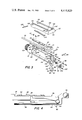
- FIG. 6 is a detailed showing of the rack and pinion arrangement for the adjustable stem
- FIG. 7 is a top plan view of the wedge locking mechanism for the FIG. 6 device.
- FIG. 8 is a view in side elevation of the transfer rod
- FIG. 9 is a bottom plan view thereof.
- FIG. 10 is a top plan view thereof
- FIG. 11 is an end view of the transfer rod together with the support pin associated therewith
- FIG. 12 is a top plan view of the head assembly
- FIG. 13 is a view in side elevation thereof partly broken away, and,
- FIG. 14 is an end view of the head.
- the reference character 10 generally indicates a bore gauge head adapted for use with a dial indicator 12, as shown in FIG. 1, or with linear variable differential transformer 14 having a digital electronic display 16, as suggested in FIG. 2.
- the head assembly is organized about a body 18, best shown in FIG. 3, of generally cylindrical contours at the rearward or left hand end thereof, but formed with matching cutaway portions 20 and 22 extending forwardly along both sides of the body to define a pair of longitudinal flat shoulders 24 and 26.
- the cutaway portions 20 and 22 also define a pair of flat faces 28 and 30 perpendicular to the shoulders 24 and 26.
- the body 18 is also bifurcated lengthwise by a longitudinal slot 32 extending from the cylindrical inner portion to the distal end thereof to form thereby a pair of spaced parallel walls 34 and 36. Communicating with the slot 32 is a shallow recess 37 at the inner end of the body at the base of the slot to receive a leaf spring 38 fastened by screws 40 and 42 threaded into cooperating tapped holes 44 and 46 in the face of the recess 37.
- the leaf spring 38 serves as a pivotal and resilient support for a sensing finger 48 dimensioned to fit with ample clearance within the slot 32.
- the body 18 is also formed with a threaded neck 50 at the left hand inner end thereof for mounting the head assembly to an extension shank 52 of a dial indicator, as shown in FIG. 1 or to an end of the LVDT as shown in FIG. 2.
- the body is also formed with an axial passage 54 extending through the neck 50 and into the slot 32 to slidably receive a transfer rod 56 shown in detail in FIGS. 8 through 11.
- the left hand end of the transfer rod 56 is adapted to drivingly engage an actuating stem on the dial indicator 12 or the movable part of the LVDT 14.
- the right hand end of the transfer rod drivingly engages a hard metal ball 58 carried by the sensitive finger 48 and shown best in FIG. 4.
- any motion of the sensitive finger 48 about its flex joint provided by the leaf spring 38 which motion will be arcuate, will be converted to a linear motion via the ball 58 to the transfer rod which will move along the axis of the rod and thereby produce a readout on the dial indicator, LVDT, or the like.
- the transfer rod 56 at its left hand end rides in a bushing 60, typically bronze or the like, while the right hand end is supported on one side by means of a pin 62 mounted transversely to the body 18 near the forward end thereof and across the lower part of the slot 32.
- the distal end of the transfer rod 56 is formed with a smooth lower face 64 bearing against the pin 62 and formed with a central longitudinal groove 66 defining a pair of parallel longitudinal narrow lands 68 and 70.
- the generally flat face 64 serve to prevent rotation of the transfer rod 56 while the groove and land configuration of the face 64 minimizes displacement of the rod in the event of imperfections or the presence of foreign matter between the transfer rod and the pin 62.
- the two lands 68 and 70 on the face 66 are flat ground and provide line contact with the pin 62. This arrangement tends to be self-cleaning and prevents sludge from building up in this area. Also, by using two flat lands spaced from one another a stabilizing effect is achieved. This also reduces the effect of asperity on the pin bearing surface. If a single flat surface were employed the effect on the rod from any asperity on the pin bearing surface would be substantially double that which would be produced using the groove and land configuration employed in the present invention. Any asperity present on the pin along the center line of the travel of the transfer rod will have no effect on the transfer rod since it will be in the clearance provided by the groove 66.
- the forward end of the transfer rod is formed with a single Vee-groove 72 diagonally across the tip to bear against the ball 58 shown in FIG. 4.
- Lapped into the Vee-groove is a pair of parallel semi-cylindrical shallow grooves 59 in which the ball 58 moves and which ensure that the ball 58 always rides in the same track and greatly improves the durability of the instrument.
- a sensitive ball contact 74 which is adapted to engage the work surface and through which the finger is biased and the transfer rod 56 moved to actuate the dial indicator. It will be understood that the arcuate motion of the finger 48 will be translated to a linear motion of the transfer rod 56 which, in turn, will produce a measurement display on the dial indicator or digital readout. Both the sensitive ball contact 74 as well as the ball 58 are replaceable in the event that either or both become worn. Upward movement of the sensitive finger 48 is limited by means of a cross pin 75 mounted to the body across the slot 32.
- an extensible stem 76 is mounted for limited movement along a path perpendicular to the length of the body and in line with the sensitive ball contact 74.
- the stem 76 in the illustrated embodiment, is formed with a flat forward face 78, which may be inscribed with graduated markings, and with tapered side walls 80 and 82 forming a wedge configuration that fits smoothly within a guideway formed in the inside faces of the body walls 34 and 36 near the tip.
- the guideway is comprised of a pair of oppositely facing tapered grooves 84 and 86 which receive the tapered sidewalls 80 and 82 of the stem.
- the stem is slidably mounted within the groove but its position within the guideway is controlled by means of a pinion 84 rotatably mounted in a corresponding socket 86 formed in the forward tip of the body adjacent to the guideway and in mesh with rack teeth 88 formed along the face 82 of the stem, as best shown in FIG. 6.
- the pinion is provided with a hex socket 90 to receive one end of a hex wrench by means of which the pinion may be rotated and thereby move the stem in or out as required in making a preliminary setting of the stem prior to performing a measuring operation.
- the exposed end may also be slotted or formed with a cross to receive a screwdriver or similar tool to rotate the pinion.
- the rotation of the pinion and the adjustment of the stem may be carried out with the instrument in place within a setting ring rather than going through a number of adjustments required for conventional screw-type stems common in the art.
- the lower end of the stem 76 is provided with a ball contact 92 pressed into a cooperating socket formed within the lower end of the stem. The ball may be replaced by forcing the ball out of its socket by inserting a narrow tool into an opening 94 formed in the stem adjacent the upper part of the ball 92.
- a plate 96 which extends partially over the face 78 of the stem and bears Vernier scale markings along the margin thereof by means of which the position of the stem may be visually determined.
- the stem 76 may be provided in several different lengths for each instrument and that the stems are readily replaced depending upon the dimensions of the work being measured.
- a locking wedge 98 Once the stem position has been adjusted, it may be locked in position by means of a locking wedge 98.
- the wedge 98 is mounted within a cutaway portion 100 adjacent to the guideway for the stem and opposite the pinion and is held by means of a locking screw 102 which passes through an opening 104 through the wedge and threadably engages a tapped socket 106 at the rear of the cutaway portion 100.
- the wedge is formed with a tapered face 108 adapted to engage the tapered face 80 of the stem and by tightening the screw 102 the wedge can lock the stem without causing any disturbance in the position of the stem, holding it firmly in place during measuring operations.
- the screw 102 is formed with a hex socket in the end thereof or may be provided with a conventional screw head for manipulation by a conventional screwdriver or the like.
- an annular spring washer 110 may be mounted on the inner end of the screw 102 between the wedge 98 and the portion around the tapped hole 106 so as to automatically release the wedge when the screw 102 is loosened and permit readjustment of the stem when required.
- the face 108 preferably is formed with a shallow groove 111 along the center thereof which defines two flats on the wedging face. This increases bearing pressure on the stem and makes the stem more stable. If a simple flat surface on the wedging face were used any slight rounding of the face would produce a line contact with stem and possible rocking thereof.
- a U-shaped centralizer arm 112 mounted to the body 18 and forming part of the head assembly is a U-shaped centralizer arm 112 comprised of a pair of parallel legs 114 and 116 joined by a cross-portion 118.
- the centralizer arm 112 is pivotally connected to the body portion by means of a pin 120 secured in cooperating holes 122 and 124 of the legs and passing through a hole 126 formed in the body near the rear of the cutaway portions 20 and 22.
- the outer surfaces of the legs 114 and 116 are curved to conform with the overall cylindrical curvature of the body and thereby eliminate any outward projection that might interfere with the taking of measurements in a bore.
- the dimensions of the legs are such that the centralizer arm fits snugly within the cutaway portions 20 and 22 yet with adequate clearance with the surfaces of the cutaway portions as to allow for free and easy movement of the arm without binding, particularly in the presence of debris, liquid coolants, or the like, that may find their way into the head assembly during normal use of the instrument.
- the centralizer arm 112 is normally biased in a counterclockwise direction, as viewed in FIGS. 1 and 13, by means of a pair of leaf springs 128 and 130 secured at their inner ends to the lower faces of the arms 114 and 116, respectively, with their forward ends extending diagonally downwards and forwards to terminate in an upwardly curved tip and bearing against the longitudinal shoulders 24 and 26 of the cutaway portions 20 and 22.
- the upward motion of the centralizer arm 112 is limited by means of a set screw 132 threaded through a tapped opening near the rear of the body 18 with its inner end engaging an inner most end of one of the legs of the centralizer rearwardly of the pivot pin 120, as best shown in FIG. 13.
- Other means may be provided for limiting the movement of the centralizer arm such as a strut or pin extending across the top of the body over the slot 32, for example.
- other springs means may be provided such as a coil spring arrangement which might extend lengthwise within the body to engage the arm at one end and a fixed portion of the body at another end to provide a bias to the arm.
- a pair of centralizer balls 134 and 136 mounted for limited transverse movement within semicylindrical grooves 138 and 140, respectively, oriented transversely of the arm.
- the depth of the grooves is such that a portion of both balls 134 and 136 extends outwardly from the centralizer arm, as best shown in FIGS. 5 and 14, in position to bear against the cylindrical inner face of a bore or reference ring.
- inserts 142 and 144 of a hard metal such as tungsten carbide or the like may be set into the walls 28 and 30, as best shown in FIGS. 3 and 12.
- the surface of the walls 28 and 30 along the lines of contact with the centralizer balls may be work hardened during the fabrication of the head assembly. This may be done by pressing the balls tightly against the walls 28, 30 and moving the centralizer arm 112 repeatedly up and down to burnish in a track for the balls.
- the instrument is used in the following manner; assuming the proper extension stem 76 is in place, the head is inserted in a selected reference ring and the centralizer arm will locate the sensitive elements, namely the balls contacts 74 and 92 along the diameter of the reference ring.
- the stem 94 is moved in or out as required to adjust the instrument to the reference ring, this being done with the head assembly in place and by simply turning the pinion 84 one way or the other.
- the stem is locked in position by tightening up the screw 102 to engage the wedge 98.
- the instrument is then withdrawn from the reference ring and inserted in the bore that is to be measured.
- the centralizer balls will precisely orient the instrument in a plane along the diameter of the bore and the axial centerline of the bore is established by rocking the instrument slightly up and down within the bore to define the smallest measurement on the dial indicator or other measuring instrument. This will represent the precise diameter of the bore.
Landscapes
- Physics & Mathematics (AREA)
- General Physics & Mathematics (AREA)
- A Measuring Device Byusing Mechanical Method (AREA)
Abstract
Description
Claims (26)
Priority Applications (2)
| Application Number | Priority Date | Filing Date | Title |
|---|---|---|---|
| US06/288,985 US4419829A (en) | 1981-07-31 | 1981-07-31 | Head for bore gauge |
| US06/356,947 US4419830A (en) | 1981-07-31 | 1982-03-11 | Bore gauge head assembly |
Applications Claiming Priority (1)
| Application Number | Priority Date | Filing Date | Title |
|---|---|---|---|
| US06/288,985 US4419829A (en) | 1981-07-31 | 1981-07-31 | Head for bore gauge |
Related Child Applications (1)
| Application Number | Title | Priority Date | Filing Date |
|---|---|---|---|
| US06/356,947 Continuation-In-Part US4419830A (en) | 1981-07-31 | 1982-03-11 | Bore gauge head assembly |
Publications (1)
| Publication Number | Publication Date |
|---|---|
| US4419829A true US4419829A (en) | 1983-12-13 |
Family
ID=23109508
Family Applications (1)
| Application Number | Title | Priority Date | Filing Date |
|---|---|---|---|
| US06/288,985 Expired - Fee Related US4419829A (en) | 1981-07-31 | 1981-07-31 | Head for bore gauge |
Country Status (1)
| Country | Link |
|---|---|
| US (1) | US4419829A (en) |
Cited By (15)
| Publication number | Priority date | Publication date | Assignee | Title |
|---|---|---|---|---|
| US4651430A (en) * | 1985-12-19 | 1987-03-24 | Vasku George O | Snap gage |
| US4926559A (en) * | 1988-03-15 | 1990-05-22 | Rheinmetall Gmbh | Measuring device for determining the position of workpiece faces |
| US5063687A (en) * | 1990-09-27 | 1991-11-12 | Equipment Development Services | Adjustable measuring parallels |
| US5224274A (en) * | 1992-03-12 | 1993-07-06 | The Edmunds Manufacturing Company | Contact gage |
| WO1995001547A1 (en) * | 1993-07-01 | 1995-01-12 | Marposs Societa' Per Azioni | Gauges for checking linear dimensions |
| US5440819A (en) * | 1994-04-19 | 1995-08-15 | Comtorgage Corporation | Actuator and programmable amplifier for an expanding plug gage head |
| US5836624A (en) * | 1993-06-25 | 1998-11-17 | Financiere De Segur | Metal part including a spherical wall element, and an exhaust ball-coupling including such a part |
| US6490805B1 (en) | 2000-10-31 | 2002-12-10 | Utvecklings Ab Uranienburg | Bore gage head assembly |
| US8278779B2 (en) | 2011-02-07 | 2012-10-02 | General Electric Company | System and method for providing redundant power to a device |
| US20130152409A1 (en) * | 2010-08-20 | 2013-06-20 | Nippon Steel & Sumitomo Metal Corporation | Method and device for inspecting a threading of a tubular connection used in the oil industry |
| US8558408B2 (en) | 2010-09-29 | 2013-10-15 | General Electric Company | System and method for providing redundant power to a device |
| US20160123714A1 (en) * | 2014-11-03 | 2016-05-05 | Boe Technology Group Co., Ltd. | Measuring tool |
| US20170074631A1 (en) * | 2015-09-16 | 2017-03-16 | Shane S. Turay | Device for inspecting and measuring sewer/utility structures |
| US10030961B2 (en) | 2015-11-27 | 2018-07-24 | General Electric Company | Gap measuring device |
| US10571235B2 (en) * | 2018-03-07 | 2020-02-25 | Honda Motor Co., Ltd. | Flange check tool |
Citations (13)
| Publication number | Priority date | Publication date | Assignee | Title |
|---|---|---|---|---|
| US1671168A (en) * | 1924-06-26 | 1928-05-29 | Zeiss Carl Fa | Caliper gauge |
| US2424497A (en) * | 1945-11-19 | 1947-07-22 | Nilsson Gage Company Inc | Bore gauge |
| US2565844A (en) * | 1946-05-09 | 1951-08-28 | Eisele Andrew | Equalizing and aligning mechanism for gauges |
| US2930134A (en) * | 1956-11-06 | 1960-03-29 | Starrett L S Co | Bore measuring dial gauge |
| US3103748A (en) * | 1960-08-16 | 1963-09-17 | Alfred H Emery | Bore gauge |
| US3418720A (en) * | 1967-02-17 | 1968-12-31 | Fed Products Corp | Bore gage with shock absorbing motion transmitting means |
| US3422540A (en) * | 1967-02-17 | 1969-01-21 | Federal Prod Corp | Bore gage |
| US3442020A (en) * | 1967-02-23 | 1969-05-06 | Federal Prod Corp | Centering means for a bore gage |
| US3762057A (en) * | 1971-01-27 | 1973-10-02 | C Kaifesh | Gage |
| US3995374A (en) * | 1975-08-26 | 1976-12-07 | Fisk James C | Small internal diameter bore gauge |
| US4030202A (en) * | 1974-07-08 | 1977-06-21 | Federal Products Corporation | Bore gage |
| US4045877A (en) * | 1976-03-11 | 1977-09-06 | Sunnen Products Company | Retractable dial bore gauge |
| US4170831A (en) * | 1978-06-21 | 1979-10-16 | Federal Products Corporation | Bore gage |
-
1981
- 1981-07-31 US US06/288,985 patent/US4419829A/en not_active Expired - Fee Related
Patent Citations (13)
| Publication number | Priority date | Publication date | Assignee | Title |
|---|---|---|---|---|
| US1671168A (en) * | 1924-06-26 | 1928-05-29 | Zeiss Carl Fa | Caliper gauge |
| US2424497A (en) * | 1945-11-19 | 1947-07-22 | Nilsson Gage Company Inc | Bore gauge |
| US2565844A (en) * | 1946-05-09 | 1951-08-28 | Eisele Andrew | Equalizing and aligning mechanism for gauges |
| US2930134A (en) * | 1956-11-06 | 1960-03-29 | Starrett L S Co | Bore measuring dial gauge |
| US3103748A (en) * | 1960-08-16 | 1963-09-17 | Alfred H Emery | Bore gauge |
| US3422540A (en) * | 1967-02-17 | 1969-01-21 | Federal Prod Corp | Bore gage |
| US3418720A (en) * | 1967-02-17 | 1968-12-31 | Fed Products Corp | Bore gage with shock absorbing motion transmitting means |
| US3442020A (en) * | 1967-02-23 | 1969-05-06 | Federal Prod Corp | Centering means for a bore gage |
| US3762057A (en) * | 1971-01-27 | 1973-10-02 | C Kaifesh | Gage |
| US4030202A (en) * | 1974-07-08 | 1977-06-21 | Federal Products Corporation | Bore gage |
| US3995374A (en) * | 1975-08-26 | 1976-12-07 | Fisk James C | Small internal diameter bore gauge |
| US4045877A (en) * | 1976-03-11 | 1977-09-06 | Sunnen Products Company | Retractable dial bore gauge |
| US4170831A (en) * | 1978-06-21 | 1979-10-16 | Federal Products Corporation | Bore gage |
Cited By (19)
| Publication number | Priority date | Publication date | Assignee | Title |
|---|---|---|---|---|
| US4651430A (en) * | 1985-12-19 | 1987-03-24 | Vasku George O | Snap gage |
| US4926559A (en) * | 1988-03-15 | 1990-05-22 | Rheinmetall Gmbh | Measuring device for determining the position of workpiece faces |
| US5063687A (en) * | 1990-09-27 | 1991-11-12 | Equipment Development Services | Adjustable measuring parallels |
| US5224274A (en) * | 1992-03-12 | 1993-07-06 | The Edmunds Manufacturing Company | Contact gage |
| US5836624A (en) * | 1993-06-25 | 1998-11-17 | Financiere De Segur | Metal part including a spherical wall element, and an exhaust ball-coupling including such a part |
| WO1995001547A1 (en) * | 1993-07-01 | 1995-01-12 | Marposs Societa' Per Azioni | Gauges for checking linear dimensions |
| US5746003A (en) * | 1993-07-01 | 1998-05-05 | Marposs Societa Per Azioni | Gauges for checking linear dimensions |
| US5440819A (en) * | 1994-04-19 | 1995-08-15 | Comtorgage Corporation | Actuator and programmable amplifier for an expanding plug gage head |
| US6490805B1 (en) | 2000-10-31 | 2002-12-10 | Utvecklings Ab Uranienburg | Bore gage head assembly |
| US20130152409A1 (en) * | 2010-08-20 | 2013-06-20 | Nippon Steel & Sumitomo Metal Corporation | Method and device for inspecting a threading of a tubular connection used in the oil industry |
| US9032632B2 (en) * | 2010-08-20 | 2015-05-19 | Vallourec Oil And Gas France | Method and device for inspecting a threading of a tubular connection used in the oil industry |
| US8558408B2 (en) | 2010-09-29 | 2013-10-15 | General Electric Company | System and method for providing redundant power to a device |
| US8278779B2 (en) | 2011-02-07 | 2012-10-02 | General Electric Company | System and method for providing redundant power to a device |
| US20160123714A1 (en) * | 2014-11-03 | 2016-05-05 | Boe Technology Group Co., Ltd. | Measuring tool |
| US9823056B2 (en) * | 2014-11-03 | 2017-11-21 | Boe Technology Group Co., Ltd. | Measuring tool |
| US20170074631A1 (en) * | 2015-09-16 | 2017-03-16 | Shane S. Turay | Device for inspecting and measuring sewer/utility structures |
| US10443995B2 (en) * | 2015-09-16 | 2019-10-15 | Shane S. Turay | Device for inspecting and measuring sewer/utility structures |
| US10030961B2 (en) | 2015-11-27 | 2018-07-24 | General Electric Company | Gap measuring device |
| US10571235B2 (en) * | 2018-03-07 | 2020-02-25 | Honda Motor Co., Ltd. | Flange check tool |
Similar Documents
| Publication | Publication Date | Title |
|---|---|---|
| US4419829A (en) | Head for bore gauge | |
| EP0251485A1 (en) | Surgical scalpel | |
| US6490805B1 (en) | Bore gage head assembly | |
| US4419830A (en) | Bore gauge head assembly | |
| US4809440A (en) | In dial bore gages | |
| EP0105979B1 (en) | Head for bore gauge | |
| US4126940A (en) | Adjustable fork gauge | |
| US4228595A (en) | Tool setting gage | |
| US4547970A (en) | Thread anvils for inside micrometer | |
| US4970799A (en) | Device for measuring a shaft keyway and method of using | |
| US4058901A (en) | Plug gage | |
| US1355724A (en) | Calipers | |
| US2121848A (en) | Indicator | |
| US2952916A (en) | Calliper squares | |
| US2938272A (en) | Gauge apparatus and a transfer mechanism therefor | |
| US2702430A (en) | Angle indicator | |
| US2791033A (en) | Adapter for dial indicators | |
| US1451736A (en) | Internal gauge | |
| US2203984A (en) | Indicating and measuring instrument | |
| US2910781A (en) | Dial hole gauge | |
| US2521825A (en) | Micrometer caliper | |
| US4398351A (en) | Thread lead gauge | |
| US4062122A (en) | Fixture for setting the stationary gaging contact on a dial bore gage | |
| US3070891A (en) | Dial indicator caliper gage | |
| US3386173A (en) | Dial reading calipers |
Legal Events
| Date | Code | Title | Description |
|---|---|---|---|
| AS | Assignment |
Owner name: FEDERAL PRODUCTS CORPORATION, PROVIDENCE, R.I. A C Free format text: ASSIGNMENT OF ASSIGNORS INTEREST.;ASSIGNOR:MILLER, MARK H.;REEL/FRAME:003921/0581 Effective date: 19810724 |
|
| MAFP | Maintenance fee payment |
Free format text: PAYMENT OF MAINTENANCE FEE, 4TH YEAR, PL 96-517 (ORIGINAL EVENT CODE: M170); ENTITY STATUS OF PATENT OWNER: LARGE ENTITY Year of fee payment: 4 |
|
| AS | Assignment |
Owner name: CONTINENTAL BANK N.A., 231 S. LASALLE ST., CHICAGO Free format text: SECURITY INTEREST;ASSIGNOR:FEDERAL PRODUCTS CORPORATION;REEL/FRAME:005673/0056 Effective date: 19910217 |
|
| FEPP | Fee payment procedure |
Free format text: MAINTENANCE FEE REMINDER MAILED (ORIGINAL EVENT CODE: REM.); ENTITY STATUS OF PATENT OWNER: LARGE ENTITY |
|
| AS | Assignment |
Owner name: FEDERAL PRODUCTS CO. Free format text: CHANGE OF NAME;ASSIGNOR:FEDERAL PRODUCTS CORPORATION A CORP. OF DE;REEL/FRAME:005870/0166 Effective date: 19910306 |
|
| LAPS | Lapse for failure to pay maintenance fees | ||
| FP | Lapsed due to failure to pay maintenance fee |
Effective date: 19911215 |
|
| STCH | Information on status: patent discontinuation |
Free format text: PATENT EXPIRED DUE TO NONPAYMENT OF MAINTENANCE FEES UNDER 37 CFR 1.362 |