EP0105979B1 - Head for bore gauge - Google Patents
Head for bore gauge Download PDFInfo
- Publication number
- EP0105979B1 EP0105979B1 EP19820305322 EP82305322A EP0105979B1 EP 0105979 B1 EP0105979 B1 EP 0105979B1 EP 19820305322 EP19820305322 EP 19820305322 EP 82305322 A EP82305322 A EP 82305322A EP 0105979 B1 EP0105979 B1 EP 0105979B1
- Authority
- EP
- European Patent Office
- Prior art keywords
- rod
- bore
- groove
- head
- arm
- Prior art date
- Legal status (The legal status is an assumption and is not a legal conclusion. Google has not performed a legal analysis and makes no representation as to the accuracy of the status listed.)
- Expired
Links
Images


Classifications
-
- G—PHYSICS
- G01—MEASURING; TESTING
- G01B—MEASURING LENGTH, THICKNESS OR SIMILAR LINEAR DIMENSIONS; MEASURING ANGLES; MEASURING AREAS; MEASURING IRREGULARITIES OF SURFACES OR CONTOURS
- G01B3/00—Measuring instruments characterised by the use of mechanical techniques
- G01B3/46—Plug gauges for internal dimensions with engaging surfaces which are at a fixed distance, although they may be preadjustable
-
- G—PHYSICS
- G01—MEASURING; TESTING
- G01B—MEASURING LENGTH, THICKNESS OR SIMILAR LINEAR DIMENSIONS; MEASURING ANGLES; MEASURING AREAS; MEASURING IRREGULARITIES OF SURFACES OR CONTOURS
- G01B3/00—Measuring instruments characterised by the use of mechanical techniques
- G01B3/002—Details
-
- G—PHYSICS
- G01—MEASURING; TESTING
- G01B—MEASURING LENGTH, THICKNESS OR SIMILAR LINEAR DIMENSIONS; MEASURING ANGLES; MEASURING AREAS; MEASURING IRREGULARITIES OF SURFACES OR CONTOURS
- G01B3/00—Measuring instruments characterised by the use of mechanical techniques
- G01B3/22—Feeler-pin gauges, e.g. dial gauges
- G01B3/26—Plug gauges
Definitions
- This invention relates generally to a new and improved head assembly for use with bore gauges of mechanical or electronic construction according to the precharacterising part of claim 1 or claim 9.
- Such a bore gauge is an instrument designed to measure inside diameters of various cylindrical bores and is well known from the disclosure DE-B-2 543 779. Machinists, for example, frequently need to make precise measurements of the diameter of a bore being cut into a workpiece. Since the sensing contact of a bore gauge typically has a relatively small range of motion, the effective measurement range of the instrument can be increased by providing an extensible stem directly opposite the sensing contact of the gauge. Such stems heretofor there have been in the form of screws that are turned in or out as required with the particular setting being established by inserting the head of the bore gauge in a reference ring selected to correspond approximately with the diameter of the bore to be' measured. Once the bore gauge has been set in the reference ring, the head of the instrument is then inserted in the bore itself and a reading is made, typically on a dial indicator mechanically connected to the measuring head.
- Another object of this invention is to provide improvements in bore gauges.
- Another object of this invention is to provide a measuring head for a bore gauge adapted to actuate either a mechanical instrument such as a dial indicator or an electrical instrument such as a linear variable differential transformer coupled to an electronic digital display.
- a further object of this invention is to provide in a bore gauge a head that may be quickly and easily set in a reference ring prior to use in measuring a bore.
- Still another object of this invention is to provide in a bore gauge a head that is easily cleaned, is long wearing and requires a minimum amount of maintenance while providing very reliable, repeatable and precise measurements.
- a head for a bore gauge having a movable member therein adapted to produce an indication of measurement corresponding to the extent of displacement of said member, a body and connecting means for operatively connecting said body to said gauge, said head being characterised by the features in the characterising part of claim 1 or of claim 9.
- the reference character 10 generally indicates a bore gauge head adapted for use with a dial indicator 12, as shown in Fig. 1, or with linear variable differential transformer 14 having a digital electronic display 16, as suggested in Fig. 2.
- the head assembly is organized about a body 18, best shown in Fig. 3, of generally cylindrical contours at the rearward or left hand end thereof, but formed with matching cutaway portions 20 and 22 extending forwardly along both sides of the body to define a pair of longitudinal flat shoulders 24 and 26.
- the cutaway portions 20 and 22 also define a pair of flat faces 28 and 30 perpendicular to the shoulders 24 and 26.
- the body 18 is also bifurcated lengthwise by a longitudinal slot 32 extending from the cylindrical inner portion to the distal end thereof to form thereby a pair of spaced parallel walls 34 and 36. Communicating with the slot 32 is a shallow recess 37 at the inner end of the body at the base of the slot to receive a leaf spring 38 fastened by screws 40 and 42 threaded into cooperating tapped holes 44 and 46 in the face of the recess 37.
- the leaf spring 38 serves as a pivotal and resilient support for a sensing finger 48 dimensioned to fit with ample clearance within the slot 32.
- the body 18 is also formed with a threaded neck 50 at the left hand inner end thereof for mounting the head assembly to an extension shank 52 of a dial indicator, as shown in Fig. 1 or to an end of the LVDT as shown in Fig. 2.
- the body is also formed with an axial passage 54 extending through the neck 50 and into the slot 32 to slidably receive a transfer rod 56 shown in detail in Figs. 8 to 11.
- the left hand end of the transfer rod 56 is adapted drivingly to engage an actuating stem on the dial indicator 12 or the movable part of the LVDT 14.
- the right hand end of the transfer rod drivingly engages a hard metal ball 58 carried by the sensitive finger 48 and shown best in Fig. 4.
- any motion of the sensitive finger 48 about its flex joint provided by the leaf spring 38 which motion will be arcuate, will be converted to a linear motion via the ball 58 to the transfer rod which will move along the axis of the rod and thereby produce a readout on the dial indicator, LVDT, or the like.
- the transfer rod 56 at its left hand end rides in a bushing 60 typically bronze or the like, while the right hand end is supported on one side by means of a pin 62 mounted transversely to the body 18 near the forward end thereof and across the lower part of the slot 32.
- the distal end of the transfer rod 56 is formed with a smooth lower face 64 bearing against the pin 62 and formed with a central longitudinal groove 66 defining a pair of parallel longitudinal narrow lands 68 and 70.
- the generally flat face 64 serves to prevent rotation of the transfer rod 56 while the groove and land configuration of the face 64 minimizes displacement of the rod in the event of imperfections or the presence of foreign matter between the transfer rod and the pin 62.
- the two lands 68 and 70 on the face 66 are flat ground and provide line contact with the pin 62. This arrangement tends to be self-cleaning and prevents sludge from building up in this area. Also, by using two flat lands spaced from one another a stabilizing effect is achieved. This also reduces the effect of asperity on the pin bearing surface. If a single flat surface were employed the effect on the rod from any asperity on the pin bearing surface would be substantially double that which would be produced using the groove and land configuration employed in the present invention. Any asperity present on the pin along the centre line of the travel of the transfer rod. will have no effect on the transfer rod since it will be in the clearance provided by the groove 66.
- the forward end of the transfer rod is formed with a single Vee-groove 72 diagonally across the tip to bear against the ball 58 shown in Fig. 4.
- Lapped into the Vee-groove is a pair of parallel semi-cylindrical shallow grooves 59 in which the ball 58 moves and which ensure that the ball 58 always rides in the same track and greatly improves the durability of the instrument.
- a sensitive ball contact 74 which is adapted to engage the work surface and through which the finger is biased and the transfer rod 56 moved to actuate the dial indicator. It will be understood that the arcuate motion of the finger 48 will be translated to a linear motion of the transfer rod 56 which, in turn, will produce a measurement display on the dial indicator or digital readout. Both the sensitive ball contact 74 as well as the ball 58 are replaceable in the event that either or both become worn. Upward movement of the sensitive finger 48 is limited by means of a cross pin 75 mounted to the body across the slot 32.
- an extensible stem 76 is mounted for limited movement along a path perpendicular to the length of the body and in line with the sensitive ball contact 74.
- the stem 76 in the illustrated embodiment is formed with a flat forward face 78, which may be inscribed with graduated markings, and with tapered side walls 80 and 82 forming a wedge configuration that fits smoothly within a guideway formed in the inside faces of the body walls 34 and 36 near the tip.
- the guideway is comprised of a pair of oppositely facing tapered grooves 84 and 86 which receive the tapered sidewalls 80 and 82 of the stem.
- the stem is slidably mounted within the groove but its position within the guideway is controlled by means of a pinion 85 rotatably mounted in a corresponding socket 86 formed in the forward tip of the body adjacent to the guideway and in mesh with rack teeth 88 formed along the face 82 of the stem, as best shown in Fig. 6.
- the pinion is provided with a hex socket 90 to receive one end of a hex wrench by means of which the pinion may be rotated and thereby move the stem in or out as required in making a preliminary setting of the stem prior to performing a measuring operation.
- the exposed end may also be slotted or formed with a cross to receive a screwdriver or similar tool to rotate the pinion.
- the rotation of the pinion and the adjustment of the stem may be carried out with the instrument in place within a setting ring rather than going through a number of adjustments required for conventional screw-type stems common in the art.
- the lower end of the stem 76 is provided with a ball contact 92 pressed into a cooperating socket formed within the lower end of the stem. The ball may be replaced by forcing the ball out of its socket by inserting a narrow tool into an opening 94 formed in the stem adjacent the upper part of the ball 92.
- a plate 96 which extends partially over the face 78 of the stem and bears Vernier scale markings along the margin thereof by means of which the position of the stem may be visually determined.
- the stem 76 may be provided in several different lengths for each instrument and that the stems are readily replaced depending upon the dimensions of the work being measured.
- a locking wedge 98 Once the stem position has been adjusted, it may be locked in position by means of a locking wedge 98.
- the wedge 98 is mounted within a cutaway portion 100 adjacent to the guideway for the stem and opposite the pinion and is held by means of a locking screw 102 which passes- through an opening 104 through the wedge and threadably engages a tapped socket 106 at the rear of the cutaway portion 100.
- the wedge is formed with a tapered face 108 adapted to engage the tapered face 80 of the stem and by tightening the screw 102 the wedge can lock the stem without causing any disturbance in the position of the stem, holding it firmly in place during measuring operations.
- the screw 102 is formed with a hex socket in the end thereof or may be provided with a conventional screw head for manipulation by a conventional screwdriver or the like.
- an annular spring washer 110 may be mounted on the inner end of the screw 102 between the wedge 98 and the portion around the tapped hole 106 so as to automatically release the wedge when the screw is loosened and permit readjustment of the stem when required.
- the face 108 preferably is formed with a shallow groove 111 along the centre thereof which defines two flats on the wedging face. This increases bearing pressure on the stem and makes the stem more stable. If a simple flat surface on the wedging face were used any slight rounding of the face would produce a line contact with stem and possible rocking thereof.
- a U-shaped centraliser arm 112 mounted to the body 18 and forming part of the head assembly is a U-shaped centraliser arm 112 comprised of a pair of parallel legs 114 and 116 joined by a cross-portion 118.
- the centraliser arm 112 is pivotally connected to the body portion by means of a pin 120 secured in cooperating holes 122 and 124 of the legs and passing through a hole 126 formed in the body near the rear of the cutaway portions 20 and 22.
- the outer surfaces of the legs 114 and 116 are curved to conform with the overall cylindrical curvature of the body and thereby eliminate any outward projection that might interfere with the taking of measurements in a bore.
- the dimensions of the legs are such that the centraliser arm fits snugly within the cutaway portions 20 and 22 yet with adequate clearance with the surfaces of the cutaway portions as to allow for free and easy movement of the arm without binding, particularly in the presence of debris, liquid coolants, or the like, that may find their way into the head assembly during normal use of the instrument.
- the centraliser arm 112 is normally biassed in a counterclockwise direction, as viewed in Figs. 1 and 13, by means of a pair of leaf springs 128 and 130 secured at their inner ends to the lower faces of the arms 114 and 116, respectively, with their forward ends extending diagonally downwards and forwards to terminate in an upwardly curved tip and bearing against the longitudinal shoulders 24 and 26 of the cutaway portions 20 and 22.
- the upward motion of the centraliser arm 112 is limited by means of a set of screw 132 threaded through a tapped opening near the rear of the body 18 with its inner end engaging an inner-most end of one of the legs of the centraliser arm rearwardly of the pivot pin 120, as best shown in Fig. 13.
- Other means may be provided for limiting the movement of the centraliser arm such as a strut or pin extending across the top of the body over the slot 32, for example.
- other spring means may be provided such as a coil spring arrangement which might extend lengthwise within the body to engage the arm at one end and a fixed portion of the body at another end to provide a bias to the arm.
- centraliser balls 134 and 136 mounted for limited transverse movement within semicylindrical grooves 138 and 140, respectively, oriented transversely of the arm.
- the depth of the grooves is such that a portion of both balls 134 and 136 extends outwardly from the centraliser arm, as best shown in Figs. 5 and 14, in position to bear against the cylindrical inner face of a bore or reference ring.
- inserts 142 and 144 of a hard metal such as tungsten carbide or the like may be set into the walls 28 and 30, as best shown in Figs. 3 and 12.
- the surface of the walls 28 and 30 along the lines of contact with the centraliser balls may be work hardened during the fabrication of the head assembly. This may be done by pressing the balls tightly against the walls 28, 30 and moving the centraliser arm 112 repeatedly up and down to burnish in a track for the balls.
- the instrument is used in the following manner; assuming the proper extension stem 76 is in place, the head is inserted in a selected reference ring and the centraliser arm will locate the sensitive elements, namely the ball contacts 74 and 92 along the diameter of the reference ring.
- the stem 94 is moved in or out as required to adjust the instrument to the reference ring, this being done with the head assembly in place and by simply turning the pinion 84 one way or the other.
- the stem is locked in position by tightening up the screw 102 to engage the wedge 98.
- the instrument is then withdrawn from the reference ring and inserted in the bore that is to be measured.
- the centraliser balls will precisely orient the instrument in a plane along the diameter of the bore and the axial centre line of the bore is established by rocking the instrument slightly up and down within the bore to define the smallest measurement on the dial indicator or other measuring instrument. This will represent the precise diameter of the bore.
Description
- This invention relates generally to a new and improved head assembly for use with bore gauges of mechanical or electronic construction according to the precharacterising part of
claim 1 or claim 9. - Such a bore gauge is an instrument designed to measure inside diameters of various cylindrical bores and is well known from the disclosure DE-B-2 543 779. Machinists, for example, frequently need to make precise measurements of the diameter of a bore being cut into a workpiece. Since the sensing contact of a bore gauge typically has a relatively small range of motion, the effective measurement range of the instrument can be increased by providing an extensible stem directly opposite the sensing contact of the gauge. Such stems heretofor there have been in the form of screws that are turned in or out as required with the particular setting being established by inserting the head of the bore gauge in a reference ring selected to correspond approximately with the diameter of the bore to be' measured. Once the bore gauge has been set in the reference ring, the head of the instrument is then inserted in the bore itself and a reading is made, typically on a dial indicator mechanically connected to the measuring head.
- While this type of instrument is known in the art as exemplified by the following U.S. patents: 3,418,720, 3,442,020, 3,422,540, 4,030,202 and 4,170,831, these instruments have been somewhat difficult to use and maintain. For example, the initial setting of the extensible stem is quite slow and may require several adjustments before the stem is correctly extended and locked as by turning a locking nut, which sometimes will cause an accidental movement of the stem. Also, the contacts used both for centralizing the instrument along the diameter of the bore as well as the measuring contacts themselves tend to wear rather rapidly. Likewise other moving parts tend to experience rather rapid wear resulting in deterioration in the accuracy of the instrument. A .further disadvantage of existing bore gauges of this type has been the tendency of parts to become clogged with debris insofar as the instruments are used frequently around machining operations where liquid coolants and the like may be present.
- Accordingly, it is a general object of this invention to provide improvements in bore gauges. Another object of this invention is to provide a measuring head for a bore gauge adapted to actuate either a mechanical instrument such as a dial indicator or an electrical instrument such as a linear variable differential transformer coupled to an electronic digital display. A further object of this invention is to provide in a bore gauge a head that may be quickly and easily set in a reference ring prior to use in measuring a bore. Still another object of this invention is to provide in a bore gauge a head that is easily cleaned, is long wearing and requires a minimum amount of maintenance while providing very reliable, repeatable and precise measurements.
- According to the present invention, these objects are met by a head for a bore gauge having a movable member therein adapted to produce an indication of measurement corresponding to the extent of displacement of said member, a body and connecting means for operatively connecting said body to said gauge, said head being characterised by the features in the characterising part of
claim 1 or of claim 9. - For a better understanding of the invention and to show how the same may be carried into effect, reference will now be made by way of example, to the accompanying drawings, in which:-
- Figure 1 is a view in perspective showing a bore gauge head in use with a dial indicator,
- Figure 2 is a view similar to Fig. 1 but showing the head in use with a linear variable differential transformer,
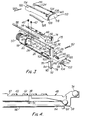
- Figure 3 is an exploded perspective view of the head,
- Figure 4 is a detailed side elevation showing the sensitive finger and transfer rod arrangement,
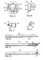
- Figure 5 is an end view of the head assembly in a setting ring,
- Figure 6 is a detailed showing of the rack and pinion arrangement for the adjustable stem,
- Figure 7 is a top plan view of the wedge locking mechanism for the Figure 6 device,
- Figure 8 is a view in side elevation of the transfer rod,
- Figure 9 is a bottom plan view thereof,
- Figure 10 is a top plan view thereof,
- Figure 11 is an end view of the transfer rod together with the support pin associated therewith,
- Figure 12 is a top plan view of the head assembly,
- Figure 13 is a view in side elevation thereof partly broken away, and
- Figure 14 is an end view of the head.
- Referring now to the drawings, the
reference character 10 generally indicates a bore gauge head adapted for use with adial indicator 12, as shown in Fig. 1, or with linear variabledifferential transformer 14 having a digitalelectronic display 16, as suggested in Fig. 2. In either event, the head assembly is organized about abody 18, best shown in Fig. 3, of generally cylindrical contours at the rearward or left hand end thereof, but formed with matchingcutaway portions 20 and 22 extending forwardly along both sides of the body to define a pair of longitudinalflat shoulders 24 and 26. Thecutaway portions 20 and 22 also define a pair offlat faces shoulders 24 and 26. Thebody 18 is also bifurcated lengthwise by alongitudinal slot 32 extending from the cylindrical inner portion to the distal end thereof to form thereby a pair of spacedparallel walls slot 32 is ashallow recess 37 at the inner end of the body at the base of the slot to receive aleaf spring 38 fastened byscrews holes recess 37. Theleaf spring 38 serves as a pivotal and resilient support for a sensingfinger 48 dimensioned to fit with ample clearance within theslot 32. - The
body 18 is also formed with a threadedneck 50 at the left hand inner end thereof for mounting the head assembly to anextension shank 52 of a dial indicator, as shown in Fig. 1 or to an end of the LVDT as shown in Fig. 2. - The body is also formed with an
axial passage 54 extending through theneck 50 and into theslot 32 to slidably receive atransfer rod 56 shown in detail in Figs. 8 to 11. The left hand end of thetransfer rod 56, as viewed in the drawings, is adapted drivingly to engage an actuating stem on thedial indicator 12 or the movable part of theLVDT 14. The right hand end of the transfer rod drivingly engages ahard metal ball 58 carried by thesensitive finger 48 and shown best in Fig. 4. It will be understood that any motion of thesensitive finger 48 about its flex joint provided by theleaf spring 38, which motion will be arcuate, will be converted to a linear motion via theball 58 to the transfer rod which will move along the axis of the rod and thereby produce a readout on the dial indicator, LVDT, or the like. - The
transfer rod 56 at its left hand end rides in a bushing 60 typically bronze or the like, while the right hand end is supported on one side by means of apin 62 mounted transversely to thebody 18 near the forward end thereof and across the lower part of theslot 32. The distal end of thetransfer rod 56 is formed with a smoothlower face 64 bearing against thepin 62 and formed with a centrallongitudinal groove 66 defining a pair of parallel longitudinalnarrow lands flat face 64 serves to prevent rotation of thetransfer rod 56 while the groove and land configuration of theface 64 minimizes displacement of the rod in the event of imperfections or the presence of foreign matter between the transfer rod and thepin 62. - The two
lands face 66 are flat ground and provide line contact with thepin 62. This arrangement tends to be self-cleaning and prevents sludge from building up in this area. Also, by using two flat lands spaced from one another a stabilizing effect is achieved. This also reduces the effect of asperity on the pin bearing surface. If a single flat surface were employed the effect on the rod from any asperity on the pin bearing surface would be substantially double that which would be produced using the groove and land configuration employed in the present invention. Any asperity present on the pin along the centre line of the travel of the transfer rod. will have no effect on the transfer rod since it will be in the clearance provided by thegroove 66. If a flat surface were used with no central groove, obviously any such central asperity would cause a maximum disturbance on the rod. Any asperity present under one of the lands will have the minimum effect on the rod and would be the same if the face were totally flat. Thus, the total effect on the rod using a centrally grooved face will be approximately one-half that which would result from using a completely flat surface. - The forward end of the transfer rod is formed with a single Vee-
groove 72 diagonally across the tip to bear against theball 58 shown in Fig. 4. Lapped into the Vee-groove is a pair of parallel semi-cylindricalshallow grooves 59 in which theball 58 moves and which ensure that theball 58 always rides in the same track and greatly improves the durability of the instrument. - At the top forward portion of the
finger 48 is mounted asensitive ball contact 74 which is adapted to engage the work surface and through which the finger is biased and thetransfer rod 56 moved to actuate the dial indicator. It will be understood that the arcuate motion of thefinger 48 will be translated to a linear motion of thetransfer rod 56 which, in turn, will produce a measurement display on the dial indicator or digital readout. Both thesensitive ball contact 74 as well as theball 58 are replaceable in the event that either or both become worn. Upward movement of thesensitive finger 48 is limited by means of across pin 75 mounted to the body across theslot 32. - At the forward tip of the
body 18 anextensible stem 76 is mounted for limited movement along a path perpendicular to the length of the body and in line with thesensitive ball contact 74. Thestem 76, in the illustrated embodiment is formed with a flatforward face 78, which may be inscribed with graduated markings, and withtapered side walls body walls tapered grooves tapered sidewalls pinion 85 rotatably mounted in acorresponding socket 86 formed in the forward tip of the body adjacent to the guideway and in mesh withrack teeth 88 formed along theface 82 of the stem, as best shown in Fig. 6. - The pinion is provided with a
hex socket 90 to receive one end of a hex wrench by means of which the pinion may be rotated and thereby move the stem in or out as required in making a preliminary setting of the stem prior to performing a measuring operation. In place of asocket 90 the exposed end may also be slotted or formed with a cross to receive a screwdriver or similar tool to rotate the pinion. In either event the rotation of the pinion and the adjustment of the stem may be carried out with the instrument in place within a setting ring rather than going through a number of adjustments required for conventional screw-type stems common in the art. The lower end of thestem 76 is provided with aball contact 92 pressed into a cooperating socket formed within the lower end of the stem. The ball may be replaced by forcing the ball out of its socket by inserting a narrow tool into anopening 94 formed in the stem adjacent the upper part of theball 92. - Mounted on the forward face of the body is a plate 96 which extends partially over the
face 78 of the stem and bears Vernier scale markings along the margin thereof by means of which the position of the stem may be visually determined. It will be understood that thestem 76 may be provided in several different lengths for each instrument and that the stems are readily replaced depending upon the dimensions of the work being measured. Once the stem position has been adjusted, it may be locked in position by means of a lockingwedge 98. Thewedge 98 is mounted within acutaway portion 100 adjacent to the guideway for the stem and opposite the pinion and is held by means of a lockingscrew 102 which passes- through anopening 104 through the wedge and threadably engages a tappedsocket 106 at the rear of thecutaway portion 100. The wedge is formed with atapered face 108 adapted to engage the taperedface 80 of the stem and by tightening thescrew 102 the wedge can lock the stem without causing any disturbance in the position of the stem, holding it firmly in place during measuring operations. Thescrew 102 is formed with a hex socket in the end thereof or may be provided with a conventional screw head for manipulation by a conventional screwdriver or the like. In practice, anannular spring washer 110 may be mounted on the inner end of thescrew 102 between thewedge 98 and the portion around the tappedhole 106 so as to automatically release the wedge when the screw is loosened and permit readjustment of the stem when required. Theface 108 preferably is formed with ashallow groove 111 along the centre thereof which defines two flats on the wedging face. This increases bearing pressure on the stem and makes the stem more stable. If a simple flat surface on the wedging face were used any slight rounding of the face would produce a line contact with stem and possible rocking thereof. - Also mounted to the
body 18 and forming part of the head assembly is aU-shaped centraliser arm 112 comprised of a pair ofparallel legs cross-portion 118. Thecentraliser arm 112 is pivotally connected to the body portion by means of apin 120 secured in cooperatingholes hole 126 formed in the body near the rear of thecutaway portions 20 and 22. Preferably, the outer surfaces of thelegs cutaway portions 20 and 22 yet with adequate clearance with the surfaces of the cutaway portions as to allow for free and easy movement of the arm without binding, particularly in the presence of debris, liquid coolants, or the like, that may find their way into the head assembly during normal use of the instrument. Thecentraliser arm 112 is normally biassed in a counterclockwise direction, as viewed in Figs. 1 and 13, by means of a pair ofleaf springs arms longitudinal shoulders 24 and 26 of thecutaway portions 20 and 22. The upward motion of thecentraliser arm 112 is limited by means of a set ofscrew 132 threaded through a tapped opening near the rear of thebody 18 with its inner end engaging an inner-most end of one of the legs of the centraliser arm rearwardly of thepivot pin 120, as best shown in Fig. 13. Other means may be provided for limiting the movement of the centraliser arm such as a strut or pin extending across the top of the body over theslot 32, for example. Also, in place of the leaf springs illustrated, other spring means may be provided such as a coil spring arrangement which might extend lengthwise within the body to engage the arm at one end and a fixed portion of the body at another end to provide a bias to the arm. - At the forward portion of the centraliser arm near the
cross portion 18 is a pair ofcentraliser balls semicylindrical grooves balls balls body 18 along thewalls body 18 or were fixed to the centraliser arm, any play between the parts, especially between the arm and the body, could result in thesensing finger 48 being slightly off-centre during the actual measurement with resulting error. However, by mounting theballs walls balls walls walls walls centraliser arm 112 repeatedly up and down to burnish in a track for the balls. - The instrument is used in the following manner; assuming the proper extension stem 76 is in place, the head is inserted in a selected reference ring and the centraliser arm will locate the sensitive elements, namely the
ball contacts stem 94 is moved in or out as required to adjust the instrument to the reference ring, this being done with the head assembly in place and by simply turning thepinion 84 one way or the other. Once the extent of the stem is selected, the stem is locked in position by tightening up thescrew 102 to engage thewedge 98. The instrument is then withdrawn from the reference ring and inserted in the bore that is to be measured. The centraliser balls will precisely orient the instrument in a plane along the diameter of the bore and the axial centre line of the bore is established by rocking the instrument slightly up and down within the bore to define the smallest measurement on the dial indicator or other measuring instrument. This will represent the precise diameter of the bore.
Claims (10)
Priority Applications (2)
| Application Number | Priority Date | Filing Date | Title |
|---|---|---|---|
| DE8282305322T DE3271673D1 (en) | 1982-10-06 | 1982-10-06 | Head for bore gauge |
| EP19820305322 EP0105979B1 (en) | 1982-10-06 | 1982-10-06 | Head for bore gauge |
Applications Claiming Priority (1)
| Application Number | Priority Date | Filing Date | Title |
|---|---|---|---|
| EP19820305322 EP0105979B1 (en) | 1982-10-06 | 1982-10-06 | Head for bore gauge |
Publications (2)
| Publication Number | Publication Date |
|---|---|
| EP0105979A1 EP0105979A1 (en) | 1984-04-25 |
| EP0105979B1 true EP0105979B1 (en) | 1986-06-11 |
Family
ID=8189796
Family Applications (1)
| Application Number | Title | Priority Date | Filing Date |
|---|---|---|---|
| EP19820305322 Expired EP0105979B1 (en) | 1982-10-06 | 1982-10-06 | Head for bore gauge |
Country Status (2)
| Country | Link |
|---|---|
| EP (1) | EP0105979B1 (en) |
| DE (1) | DE3271673D1 (en) |
Families Citing this family (5)
| Publication number | Priority date | Publication date | Assignee | Title |
|---|---|---|---|---|
| FR2553877B1 (en) * | 1983-10-19 | 1985-12-27 | Commissariat Energie Atomique | PROBE FOR MEASURING THE INTERNAL DIAMETER OF A TUBE AND DEVICE FOR INTRODUCING THE SAME INTO THE TUBE |
| GB8626594D0 (en) * | 1986-11-07 | 1986-12-10 | Renishaw Plc | Rotary cutting tool |
| DE4425150A1 (en) * | 1994-07-15 | 1996-01-18 | Hartmut Hacmann | Probe for indoor measuring devices |
| US10030961B2 (en) | 2015-11-27 | 2018-07-24 | General Electric Company | Gap measuring device |
| CN113701599B (en) * | 2021-08-30 | 2024-02-27 | 湖南兴众科技有限公司 | Device and method for detecting precision of finished product for processing hydraulic valve block |
Family Cites Families (3)
| Publication number | Priority date | Publication date | Assignee | Title |
|---|---|---|---|---|
| US4030202A (en) * | 1974-07-08 | 1977-06-21 | Federal Products Corporation | Bore gage |
| CH617506A5 (en) * | 1977-04-07 | 1980-05-30 | Tesa Sa | |
| JPS622483Y2 (en) * | 1979-01-25 | 1987-01-21 |
-
1982
- 1982-10-06 EP EP19820305322 patent/EP0105979B1/en not_active Expired
- 1982-10-06 DE DE8282305322T patent/DE3271673D1/en not_active Expired
Also Published As
| Publication number | Publication date |
|---|---|
| DE3271673D1 (en) | 1986-07-17 |
| EP0105979A1 (en) | 1984-04-25 |
Similar Documents
| Publication | Publication Date | Title |
|---|---|---|
| US4419829A (en) | Head for bore gauge | |
| US4045877A (en) | Retractable dial bore gauge | |
| US4982505A (en) | Gauge for measuring both the depth and the diameter of a bore hole | |
| US2599835A (en) | Dimensional tolerance gauge | |
| US6490805B1 (en) | Bore gage head assembly | |
| US4419830A (en) | Bore gauge head assembly | |
| US4503616A (en) | Parallel motion displacement transducers | |
| EP0105979B1 (en) | Head for bore gauge | |
| US4809440A (en) | In dial bore gages | |
| US4126940A (en) | Adjustable fork gauge | |
| US4228595A (en) | Tool setting gage | |
| US4547970A (en) | Thread anvils for inside micrometer | |
| US4970799A (en) | Device for measuring a shaft keyway and method of using | |
| US3352022A (en) | Upright grinding gauge | |
| US4067114A (en) | Variable amplification expanding plug gage | |
| US2274275A (en) | Inside caliper | |
| US4058901A (en) | Plug gage | |
| US2938272A (en) | Gauge apparatus and a transfer mechanism therefor | |
| US5217336A (en) | Edge finder | |
| US2121848A (en) | Indicator | |
| US2791033A (en) | Adapter for dial indicators | |
| US4062122A (en) | Fixture for setting the stationary gaging contact on a dial bore gage | |
| US4434557A (en) | Indicator snap gage assemblies | |
| US2702430A (en) | Angle indicator | |
| US2029665A (en) | Scriber indicator |
Legal Events
| Date | Code | Title | Description |
|---|---|---|---|
| PUAI | Public reference made under article 153(3) epc to a published international application that has entered the european phase |
Free format text: ORIGINAL CODE: 0009012 |
|
| AK | Designated contracting states |
Designated state(s): CH DE GB IT LI SE |
|
| 17P | Request for examination filed |
Effective date: 19840413 |
|
| GRAA | (expected) grant |
Free format text: ORIGINAL CODE: 0009210 |
|
| AK | Designated contracting states |
Kind code of ref document: B1 Designated state(s): CH DE GB IT LI SE |
|
| PG25 | Lapsed in a contracting state [announced via postgrant information from national office to epo] |
Ref country code: LI Effective date: 19860611 Ref country code: IT Free format text: LAPSE BECAUSE OF FAILURE TO SUBMIT A TRANSLATION OF THE DESCRIPTION OR TO PAY THE FEE WITHIN THE PRESCRIBED TIME-LIMIT;WARNING: LAPSES OF ITALIAN PATENTS WITH EFFECTIVE DATE BEFORE 2007 MAY HAVE OCCURRED AT ANY TIME BEFORE 2007. THE CORRECT EFFECTIVE DATE MAY BE DIFFERENT FROM THE ONE RECORDED. Effective date: 19860611 Ref country code: CH Effective date: 19860611 |
|
| PG25 | Lapsed in a contracting state [announced via postgrant information from national office to epo] |
Ref country code: SE Effective date: 19860630 |
|
| REF | Corresponds to: |
Ref document number: 3271673 Country of ref document: DE Date of ref document: 19860717 |
|
| REG | Reference to a national code |
Ref country code: CH Ref legal event code: PL |
|
| PLBE | No opposition filed within time limit |
Free format text: ORIGINAL CODE: 0009261 |
|
| STAA | Information on the status of an ep patent application or granted ep patent |
Free format text: STATUS: NO OPPOSITION FILED WITHIN TIME LIMIT |
|
| 26N | No opposition filed | ||
| PGFP | Annual fee paid to national office [announced via postgrant information from national office to epo] |
Ref country code: DE Payment date: 19920310 Year of fee payment: 10 |
|
| PGFP | Annual fee paid to national office [announced via postgrant information from national office to epo] |
Ref country code: GB Payment date: 19921006 Year of fee payment: 11 |
|
| PG25 | Lapsed in a contracting state [announced via postgrant information from national office to epo] |
Ref country code: DE Effective date: 19930701 |
|
| PG25 | Lapsed in a contracting state [announced via postgrant information from national office to epo] |
Ref country code: GB Effective date: 19931006 |
|
| GBPC | Gb: european patent ceased through non-payment of renewal fee |
Effective date: 19931006 |