US4419792A - Reversible belt and buckle mechanism - Google Patents
Reversible belt and buckle mechanism Download PDFInfo
- Publication number
- US4419792A US4419792A US06/332,012 US33201281A US4419792A US 4419792 A US4419792 A US 4419792A US 33201281 A US33201281 A US 33201281A US 4419792 A US4419792 A US 4419792A
- Authority
- US
- United States
- Prior art keywords
- belt
- keeper
- frame
- lever
- buckle
- Prior art date
- Legal status (The legal status is an assumption and is not a legal conclusion. Google has not performed a legal analysis and makes no representation as to the accuracy of the status listed.)
- Expired - Fee Related
Links
Images

Classifications
-
- A—HUMAN NECESSITIES
- A44—HABERDASHERY; JEWELLERY
- A44B—BUTTONS, PINS, BUCKLES, SLIDE FASTENERS, OR THE LIKE
- A44B11/00—Buckles; Similar fasteners for interconnecting straps or the like, e.g. for safety belts
- A44B11/20—Buckles; Similar fasteners for interconnecting straps or the like, e.g. for safety belts engaging holes or the like in strap
- A44B11/24—Buckle with movable prong
-
- Y—GENERAL TAGGING OF NEW TECHNOLOGICAL DEVELOPMENTS; GENERAL TAGGING OF CROSS-SECTIONAL TECHNOLOGIES SPANNING OVER SEVERAL SECTIONS OF THE IPC; TECHNICAL SUBJECTS COVERED BY FORMER USPC CROSS-REFERENCE ART COLLECTIONS [XRACs] AND DIGESTS
- Y10—TECHNICAL SUBJECTS COVERED BY FORMER USPC
- Y10T—TECHNICAL SUBJECTS COVERED BY FORMER US CLASSIFICATION
- Y10T24/00—Buckles, buttons, clasps, etc.
- Y10T24/34—Combined diverse multipart fasteners
- Y10T24/3401—Buckle
-
- Y—GENERAL TAGGING OF NEW TECHNOLOGICAL DEVELOPMENTS; GENERAL TAGGING OF CROSS-SECTIONAL TECHNOLOGIES SPANNING OVER SEVERAL SECTIONS OF THE IPC; TECHNICAL SUBJECTS COVERED BY FORMER USPC CROSS-REFERENCE ART COLLECTIONS [XRACs] AND DIGESTS
- Y10—TECHNICAL SUBJECTS COVERED BY FORMER USPC
- Y10T—TECHNICAL SUBJECTS COVERED BY FORMER US CLASSIFICATION
- Y10T24/00—Buckles, buttons, clasps, etc.
- Y10T24/40—Buckles
- Y10T24/4002—Harness
- Y10T24/4012—Clamping
- Y10T24/4016—Pivoted part or lever
-
- Y—GENERAL TAGGING OF NEW TECHNOLOGICAL DEVELOPMENTS; GENERAL TAGGING OF CROSS-SECTIONAL TECHNOLOGIES SPANNING OVER SEVERAL SECTIONS OF THE IPC; TECHNICAL SUBJECTS COVERED BY FORMER USPC CROSS-REFERENCE ART COLLECTIONS [XRACs] AND DIGESTS
- Y10—TECHNICAL SUBJECTS COVERED BY FORMER USPC
- Y10T—TECHNICAL SUBJECTS COVERED BY FORMER US CLASSIFICATION
- Y10T24/00—Buckles, buttons, clasps, etc.
- Y10T24/40—Buckles
- Y10T24/4072—Pivoted lever
Definitions
- the present invention relates to a belt and buckle keeper mechanism used to interconnect the belt and buckle and permit reversal of both the belt and the buckle frame so that opposite sides of each may be independently displayed as desired.
- Another object of this invention is to provide a belt buckle construction of the above type which is easy to use, but effective and reliable in its operation.
- FIG. 1 is a perspective view of a belt buckle shown from top embodying this invention
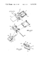
- FIG. 2 is an exploded view of the belt buckle shown in FIG. 1;
- FIG. 3 is a perspective view of a portion of the buckle
- FIG. 4 is a top plan view of the buckle
- FIG. 5 is a side elevated view of the buckle shown in combination with a belt disposed in closed condition
- FIG. 6 is a partial side elevated view of a portion of the buckle to illustrate its locking feature.
- a buckle mechanism embodying this invention is shown generally at 8 in FIG. 1.
- a belt 10 is shown fastened at its inner end to the buckle 8.
- the buckle includes a loop or frame portion 12 with a pivotable tongue 14 adapted to engage in a conventional manner longitudinally spaced holes 15 (FIG. 5), provided along the center line of the outer end portion of the belt.
- the frame 12 includes a pivot means shown as a transverse pin 13 carried at its inner end for pivotable mounting of the frame.
- the frame, tongue 14 and belt 10 are all maintained in assembled relation by means of a keeper 16.
- the frame an tongue are each pivotably mounted and independently at one end of the keeper, while the belt is latched into the opposite end as well hereafter be more fully described.
- the keeper 16 is generally in the form of a block of metal or synthetic plastic which may be fabricated by machining, casting, or injection molding techniques.
- the keeper is of unitary construction and is generally rectangular in cross section with a central bore of passageway 18 extending from end-to-end therethrough.
- the keeper 16 includes a top wall 20, an apertured bottom wall 22 and sidewalls 24.
- the keeper Disposed adjacent its inner end and bridging the upper surface, the keeper includes a belt-end retainer loop 26 for receiving and holding the free outer end of the belt 10 neatly against inner end portion of the belt 10, as shown in FIG. 5.
- the keeper 16 includes a latch lever 30 which is pivotably mounted on a transversely extending pivot pin 31 (FIG. 2). The pin extends through aligned holes in the sidewalls 24 of the keeper and a bore 32 (FIG. 2) through the latch member located adjacent the inner end thereof outwardly of a rib portion 34 of the latch member.
- the outer edge of the rib is toothed or serrated for enhanced gripping actions.
- the latch member forward of the toothed rib 34 the latch member further includes a U-shaped channel 36 to receive the inner terminal end 35 of the belt 10 when it is being fastened to the buckle as illustrated in FIG. 6.
- a transverse tongue holder bar member 38 Extending upwardly and outwardly from the central portion of the channel is a transverse tongue holder bar member 38 (FIG. 2).
- the tongue is pivotably mounted on a pin 40 extending between a pair of laterally spaced arms 42 (FIG. 4) on the forward face of the bar 38.
- the underside of the bar 38 comprises a downwardly facing channel 44 adapted to receive and retain the pivot pin 13 of frame 12 between the channel and bottom wall 22 of the keeper 16 (FIG. 5) thereby coupling the frame to the outer end of the keeper.
- the bottom wall 22 of the keeper is formed with a rectangular opening 46, which is to accomodate the latch member 30 in a generally flush arrangement as best illustrated in FIG. 5.
- the buckle mechanism embodying the invention thus includes, in addition to the belt itself, a frame 12 and keeper 16.
- the keeper includes, as a subassembly, a pivotable latching lever 30 for releasably clamping the belt and coupling pivotable frame thereto.
- FIG. 6 To assemble the components of the reversible buckle mechanism, reference is made to FIG. 6. As will be seen, the terminal end of the belt 10 is inserted into the central passageway 18 with the latch lever 30 swung to its open position generally perpendicular to the keeper 16. The U-shaped channel 36 of the latch member in this position faces forward and is adapted to receive the end of the belt. At the same time, the inner end of the frame 12 is fitted into the opposite end of the bore 18 with its pivot pin 13 positioned as shown in FIG. 6. The lever 30 may even be swung upwardly toward its horizontal position (FIG. 5), and in so doing, two locking actions occur simultaneously.
- the toothed rib 34 will tightly grip the belt 10 as it swings over the vertical or top dead center position relative to the pivot pin 31 of the latch lever.
- the downwardly facing channel 44 will couple the pivot pin 13 of the frame 12 to the keeper.
- the latch lever In its locked position, the latch lever is best illustrated in FIG. 5 wherein its outer end abuts the recessed portion of bottom wall 22.
- the toothed rib 34 when the latch lever is being swung to its closed position, will first compress the belt material to a maximum extent when the rib is perpendicular to the belt or in its "top dead center” position. Upon final closing of the lever 30, the rib 34 extends at an acute angle a relative to the perpendicular. There is thus a horizontal component of holding force exerted by the toothed rib 34, which component is along the plane of the belt.
- This geometric arrangement serves to lock securely the lever in its fully closed position. Whereby, in order to unlatch the lever 30, it is necessary to pivot its outer end over a substantial distance, through the angle a, and with increasing force to compress the belt material to the maximum extent at the perpendicular position of the rib 34. This configuration thereby prevents accidental or unintentional unlocking of lever 30, such as by a small opening movement.
Landscapes
- Buckles (AREA)
Abstract
Description
Claims (8)
Priority Applications (1)
| Application Number | Priority Date | Filing Date | Title |
|---|---|---|---|
| US06/332,012 US4419792A (en) | 1981-12-18 | 1981-12-18 | Reversible belt and buckle mechanism |
Applications Claiming Priority (1)
| Application Number | Priority Date | Filing Date | Title |
|---|---|---|---|
| US06/332,012 US4419792A (en) | 1981-12-18 | 1981-12-18 | Reversible belt and buckle mechanism |
Publications (1)
| Publication Number | Publication Date |
|---|---|
| US4419792A true US4419792A (en) | 1983-12-13 |
Family
ID=23296335
Family Applications (1)
| Application Number | Title | Priority Date | Filing Date |
|---|---|---|---|
| US06/332,012 Expired - Fee Related US4419792A (en) | 1981-12-18 | 1981-12-18 | Reversible belt and buckle mechanism |
Country Status (1)
| Country | Link |
|---|---|
| US (1) | US4419792A (en) |
Cited By (13)
| Publication number | Priority date | Publication date | Assignee | Title |
|---|---|---|---|---|
| US4584743A (en) * | 1985-09-20 | 1986-04-29 | Calabro Anthony S | Belt buckle |
| US4669155A (en) * | 1985-12-09 | 1987-06-02 | Chen Kuo Jen | Belt buckle |
| USD378582S (en) * | 1995-03-27 | 1997-03-25 | Zimmerman Richard B | Belt keeper |
| FR2750018A1 (en) * | 1996-06-21 | 1997-12-26 | Humery | Buckle for belt adjustable in length |
| US20020185215A1 (en) * | 2001-05-04 | 2002-12-12 | Ortiz Kim A. | System and process for manufacturing fastening mechanisms which connect articles and the like together |
| US20050217080A1 (en) * | 2004-04-01 | 2005-10-06 | Ramineh Kojoori | Removable fastener apparatus and method of use |
| US20110210566A1 (en) * | 2010-03-01 | 2011-09-01 | Te-Yu Chen | Latch direction change structure of lock |
| US20140215766A1 (en) * | 2013-02-07 | 2014-08-07 | Hsin-Ta Liu | Belt head with replaceable buckle portion |
| US20160021985A1 (en) * | 2013-02-07 | 2016-01-28 | Hsin-Ta Liu | Quick release buckle belt for improving efficiency in security screening procedure and method thereof |
| WO2020010658A1 (en) * | 2018-07-07 | 2020-01-16 | 泉州市璨城坊袖扣工艺有限公司 | Easy-to-disassemble turned-over double-sided waist belt buckle |
| US10939732B2 (en) * | 2019-07-27 | 2021-03-09 | Ccf Cufflink Co., Ltd. Quanzhou | Belt buckle with long usage rate |
| US10980319B1 (en) * | 2019-03-22 | 2021-04-20 | Randa Accessories Leather Goods, LLC | Reversible belt buckle |
| US20230218049A1 (en) * | 2022-04-21 | 2023-07-13 | Shenzhen Eview Gps Technology | Watch strap buckle with hidden locking device |
Citations (10)
| Publication number | Priority date | Publication date | Assignee | Title |
|---|---|---|---|---|
| US658124A (en) * | 1899-12-14 | 1900-09-18 | William W Semple | Combined buckle and snap-hook. |
| US1763100A (en) * | 1928-06-12 | 1930-06-10 | John A Mendosa | Belt buckle |
| US1775137A (en) * | 1929-11-22 | 1930-09-09 | Ostrower Harry | Buckle |
| US2186819A (en) * | 1938-08-17 | 1940-01-09 | Buchsbaum Herbert | Reversible buckle |
| US2197665A (en) * | 1938-09-03 | 1940-04-16 | Alma Mfg Company | Buckle |
| US2630612A (en) * | 1951-06-28 | 1953-03-10 | Ludwig A Stark | Yieldable belt buckle |
| US3369278A (en) * | 1965-11-08 | 1968-02-20 | Charles D. Humphreys | Reversible belt and buckle having stretch character |
| US3384936A (en) * | 1965-11-05 | 1968-05-28 | Sokoloff Raymond | Belt buckle construction having integral strap cutting means |
| US3855637A (en) * | 1973-11-05 | 1974-12-24 | B Luger | Belt reversing mechanism |
| US4281440A (en) * | 1980-02-22 | 1981-08-04 | Britz Jeffrey E | Belt buckle construction |
-
1981
- 1981-12-18 US US06/332,012 patent/US4419792A/en not_active Expired - Fee Related
Patent Citations (10)
| Publication number | Priority date | Publication date | Assignee | Title |
|---|---|---|---|---|
| US658124A (en) * | 1899-12-14 | 1900-09-18 | William W Semple | Combined buckle and snap-hook. |
| US1763100A (en) * | 1928-06-12 | 1930-06-10 | John A Mendosa | Belt buckle |
| US1775137A (en) * | 1929-11-22 | 1930-09-09 | Ostrower Harry | Buckle |
| US2186819A (en) * | 1938-08-17 | 1940-01-09 | Buchsbaum Herbert | Reversible buckle |
| US2197665A (en) * | 1938-09-03 | 1940-04-16 | Alma Mfg Company | Buckle |
| US2630612A (en) * | 1951-06-28 | 1953-03-10 | Ludwig A Stark | Yieldable belt buckle |
| US3384936A (en) * | 1965-11-05 | 1968-05-28 | Sokoloff Raymond | Belt buckle construction having integral strap cutting means |
| US3369278A (en) * | 1965-11-08 | 1968-02-20 | Charles D. Humphreys | Reversible belt and buckle having stretch character |
| US3855637A (en) * | 1973-11-05 | 1974-12-24 | B Luger | Belt reversing mechanism |
| US4281440A (en) * | 1980-02-22 | 1981-08-04 | Britz Jeffrey E | Belt buckle construction |
Cited By (17)
| Publication number | Priority date | Publication date | Assignee | Title |
|---|---|---|---|---|
| US4584743A (en) * | 1985-09-20 | 1986-04-29 | Calabro Anthony S | Belt buckle |
| US4669155A (en) * | 1985-12-09 | 1987-06-02 | Chen Kuo Jen | Belt buckle |
| USD378582S (en) * | 1995-03-27 | 1997-03-25 | Zimmerman Richard B | Belt keeper |
| FR2750018A1 (en) * | 1996-06-21 | 1997-12-26 | Humery | Buckle for belt adjustable in length |
| US20020185215A1 (en) * | 2001-05-04 | 2002-12-12 | Ortiz Kim A. | System and process for manufacturing fastening mechanisms which connect articles and the like together |
| US20050217080A1 (en) * | 2004-04-01 | 2005-10-06 | Ramineh Kojoori | Removable fastener apparatus and method of use |
| US7480967B2 (en) * | 2004-04-01 | 2009-01-27 | Fossil, Inc. | Removable fastener apparatus and method of use |
| US8366158B2 (en) * | 2010-03-01 | 2013-02-05 | Te-Yu Chen | Latch direction change structure of lock |
| US20110210566A1 (en) * | 2010-03-01 | 2011-09-01 | Te-Yu Chen | Latch direction change structure of lock |
| US20140215766A1 (en) * | 2013-02-07 | 2014-08-07 | Hsin-Ta Liu | Belt head with replaceable buckle portion |
| US9173454B2 (en) * | 2013-02-07 | 2015-11-03 | Hsin-Ta Liu | Belt head with replaceable buckle portion |
| US20160021985A1 (en) * | 2013-02-07 | 2016-01-28 | Hsin-Ta Liu | Quick release buckle belt for improving efficiency in security screening procedure and method thereof |
| US9930936B2 (en) * | 2013-02-07 | 2018-04-03 | Hsin-Ta Liu | Quick release buckle belt for improving efficiency in security screening procedure and method thereof |
| WO2020010658A1 (en) * | 2018-07-07 | 2020-01-16 | 泉州市璨城坊袖扣工艺有限公司 | Easy-to-disassemble turned-over double-sided waist belt buckle |
| US10980319B1 (en) * | 2019-03-22 | 2021-04-20 | Randa Accessories Leather Goods, LLC | Reversible belt buckle |
| US10939732B2 (en) * | 2019-07-27 | 2021-03-09 | Ccf Cufflink Co., Ltd. Quanzhou | Belt buckle with long usage rate |
| US20230218049A1 (en) * | 2022-04-21 | 2023-07-13 | Shenzhen Eview Gps Technology | Watch strap buckle with hidden locking device |
Similar Documents
| Publication | Publication Date | Title |
|---|---|---|
| US4419792A (en) | Reversible belt and buckle mechanism | |
| US4705308A (en) | Draw pull latch | |
| CA1121574A (en) | Automatically locking slider for slide fastener | |
| US5507076A (en) | Side-release buckle having improved locking feature | |
| US5443039A (en) | Releasable cat collar | |
| US4924562A (en) | Jewelry clasp | |
| US4406043A (en) | Belt buckle construction | |
| US5579563A (en) | Adjustable belt fastener with spring biased male fastener member | |
| US4930324A (en) | Center-release, lockable buckle | |
| CA1315958C (en) | Buckle assembly | |
| US20070079486A1 (en) | Buckle | |
| JPH0432915B2 (en) | ||
| US4477949A (en) | Belt buckle construction | |
| US4648161A (en) | Jewelry clasp | |
| US4894890A (en) | Buckle assembly | |
| GB2169648A (en) | A fastening device for a belt | |
| US4200404A (en) | Loose leaf binders | |
| CA1295111C (en) | Strap fastener | |
| US5638585A (en) | Separable bottom-end-stop assembly of synthetic resin for slide fastener | |
| US5297321A (en) | Fastening device | |
| MY121933A (en) | Lock slider for slide fastener | |
| CA1166829A (en) | Buckle for belts or the like | |
| US5400481A (en) | Slide for slide fastener | |
| US4751772A (en) | Two part waist buckle with snap-fitting retention feature | |
| US4584743A (en) | Belt buckle |
Legal Events
| Date | Code | Title | Description |
|---|---|---|---|
| AS | Assignment |
Owner name: BEATRICE FOODS COMPANY; CHICAGO, IL. A CORP. OF D Free format text: ASSIGNMENT OF ASSIGNORS INTEREST.;ASSIGNOR:KOHLI, JERRY L.;REEL/FRAME:003992/0789 Effective date: 19811211 Owner name: BEATRICE FOODS COMPANY,ILLINOIS Free format text: ASSIGNMENT OF ASSIGNORS INTEREST;ASSIGNOR:KOHLI, JERRY L.;REEL/FRAME:003992/0789 Effective date: 19811211 |
|
| AS | Assignment |
Owner name: BUXTON, INC., 265 MAIN ST., AGAWAM, MA 01101 AND Free format text: ASSIGNMENT OF ASSIGNORS INTEREST. EFFECTIVE MARCH 31, 1982.;ASSIGNOR:BEATRICE FOODS CO. TWO NORTH LASALLE ST., CHICAGO, IL 60603 A CORP. OF DE;REEL/FRAME:004058/0171 Effective date: 19820826 |
|
| MAFP | Maintenance fee payment |
Free format text: PAYMENT OF MAINTENANCE FEE, 4TH YEAR, PL 96-517 (ORIGINAL EVENT CODE: M170); ENTITY STATUS OF PATENT OWNER: LARGE ENTITY Year of fee payment: 4 |
|
| FEPP | Fee payment procedure |
Free format text: PAYOR NUMBER ASSIGNED (ORIGINAL EVENT CODE: ASPN); ENTITY STATUS OF PATENT OWNER: LARGE ENTITY |
|
| AS | Assignment |
Owner name: BAYBANK MIDDLESEX, MASSACHUSETTS Free format text: SECURITY INTEREST;ASSIGNOR:DHP LIMITED PARTNERSHIP;REEL/FRAME:005252/0124 Effective date: 19891130 |
|
| AS | Assignment |
Owner name: DHP LIMITED PARTNERSHIP, A DE. LIMITED PARTNERSHIP Free format text: ASSIGNMENT OF ASSIGNORS INTEREST.;ASSIGNOR:BUXTON, INC.;REEL/FRAME:005237/0795 Effective date: 19891212 |
|
| FEPP | Fee payment procedure |
Free format text: MAINTENANCE FEE REMINDER MAILED (ORIGINAL EVENT CODE: REM.); ENTITY STATUS OF PATENT OWNER: LARGE ENTITY |
|
| FEPP | Fee payment procedure |
Free format text: SURCHARGE FOR LATE PAYMENT, PL 96-517 (ORIGINAL EVENT CODE: M176); ENTITY STATUS OF PATENT OWNER: LARGE ENTITY |
|
| MAFP | Maintenance fee payment |
Free format text: PAYMENT OF MAINTENANCE FEE, 8TH YEAR, PL 96-517 (ORIGINAL EVENT CODE: M171); ENTITY STATUS OF PATENT OWNER: LARGE ENTITY Year of fee payment: 8 |
|
| AS | Assignment |
Owner name: SHAWMUT BANK CONNECTICUT, N.A., CONNECTICUT Free format text: SECURITY INTEREST;ASSIGNOR:DHP LIMITED PARTNERSHIP D/B/A BUXTON CO.;REEL/FRAME:006690/0427 Effective date: 19930913 |
|
| FEPP | Fee payment procedure |
Free format text: MAINTENANCE FEE REMINDER MAILED (ORIGINAL EVENT CODE: REM.); ENTITY STATUS OF PATENT OWNER: LARGE ENTITY |
|
| LAPS | Lapse for failure to pay maintenance fees | ||
| FP | Lapsed due to failure to pay maintenance fee |
Effective date: 19951213 |
|
| STCH | Information on status: patent discontinuation |
Free format text: PATENT EXPIRED DUE TO NONPAYMENT OF MAINTENANCE FEES UNDER 37 CFR 1.362 |