US441908A - Electric clock-alarm - Google Patents
Electric clock-alarm Download PDFInfo
- Publication number
- US441908A US441908A US441908DA US441908A US 441908 A US441908 A US 441908A US 441908D A US441908D A US 441908DA US 441908 A US441908 A US 441908A
- Authority
- US
- United States
- Prior art keywords
- alarm
- clock
- electric
- key
- circuit
- Prior art date
- Legal status (The legal status is an assumption and is not a legal conclusion. Google has not performed a legal analysis and makes no representation as to the accuracy of the status listed.)
- Expired - Lifetime
Links
- 239000004020 conductor Substances 0.000 description 3
- 238000010276 construction Methods 0.000 description 2
- 229910001369 Brass Inorganic materials 0.000 description 1
- RYGMFSIKBFXOCR-UHFFFAOYSA-N Copper Chemical compound [Cu] RYGMFSIKBFXOCR-UHFFFAOYSA-N 0.000 description 1
- 239000010951 brass Substances 0.000 description 1
- 239000010949 copper Substances 0.000 description 1
- 229910052802 copper Inorganic materials 0.000 description 1
- 230000000284 resting effect Effects 0.000 description 1
Images

Classifications
-
- G—PHYSICS
- G04—HOROLOGY
- G04C—ELECTROMECHANICAL CLOCKS OR WATCHES
- G04C21/00—Producing acoustic time signals by electrical means
- G04C21/16—Producing acoustic time signals by electrical means producing the signals at adjustable fixed times
- G04C21/20—Producing acoustic time signals by electrical means producing the signals at adjustable fixed times by closing a contact to ring an electromechanical alarm
- G04C21/22—Producing acoustic time signals by electrical means producing the signals at adjustable fixed times by closing a contact to ring an electromechanical alarm put into action by the arbor of a mechanical alarm work
Definitions
- My invention relates to an electric alarm for clocks, the object being to provide a simple and inexpensive apparatus which will work efficiently with an alarm-clock of ordinary construction.
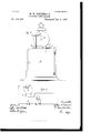
- Figure 1 is a front elevation of my invention,showing the clock in position to operate the alarm.
- Fig. 2 is atop plan view of the same.
- Fig. 3 is a rear elevation, and
- Fig. 4 is a diagrammatic view of the electrical connections.
- A is an alarm-clock of ordinary construction, in which the alarm is wound from the back by a key a, which, when the alarm sounds, revolves as the spring actuating the alarm mechanism unwinds.
- b b are plates, of copper, brass, or other good conducting material, secured to the top of the case B, on which the legs of the clock rest.
- D is alever pivoted at the rear end and provided with a projecting hook or ring D, in which one of the legs of the clock sets, and whereby, when it is desired to stop the ringing of the alarm, the clock may be moved sufficiently to break the circuit.
- d is an L-shaped piece, within which the clock sets, thus preventing its slipping or moving and breaking the electric connections.
- E is a wire, of conducting material, with which the rotating key of the clock-alarm makes contact when the alarm mechanism of the clock operates, thereby making connection from the battery F, through the wire E and clock A, through either of the plates 1) b, to the electric bell O.
- my invention is as follows: The alarm of the clock being wound and set to operate at a certain hour, the clock A is placed within the L-shaped piece cl. One leg of the said clock is inserted in the hook or ring in the lever D, which is moved over and is caught by the catch 0. The legs of the clock will then rest on the platesb b.
- the alarm mechanism of the clock operates and the rotating key a turns until it strikes the wire E, thereby completing the circuit from the battery F through wire E, key Ct, clock A, and either of the plates b b to the electric bell O, and thence back to the battery, as before described.
- an alarmclock having one of its legs removably arranged in an open circuit and a key or projection rotating with the clock-alarm mechanism, in combination with an electric connection with which the rotating key or proj ection makes contact, .thereby closing the circuit and operating the electric alarm, substantially as described.
- an electric circuit, and an alarm-clock having a key to wind said alarm mounted upon a box or inclosing-case having a plate or plates of conducting material upon which the clock-legs rest, one of said plates and the legs resting thereon being in said circuit, in combination with an electric connection with which the rotating key or projection makes contact, thereby closing the circuit and operating the electric alarm, and means for breaking the circuit, substantially as described.
Landscapes
- Physics & Mathematics (AREA)
- General Physics & Mathematics (AREA)
- Electromechanical Clocks (AREA)
Description
(No Model.) 2 SheetsSheet 1-.
L MfW. TIEDEMANN.
' ELECTRIC 'GLOOK ALARM.
'No. 441,908. Patented Dec. 2, 1890.
(No Model.) 2 sheets sheet 2.
M. W. TIEDEMANN.
ELEGTRIU CLOCK ALARM.
No. 441,908. Patented Dec. 2, 1890.
UNITED STATES PATENT OFFICE.
MATTIIIAS \V. TIEDEMANN, OF BROOKLYN, NEW YORK.
ELECTRIC CLOCK-ALARM.
SPECIFICATION forming part of Letters Patent No. 441,908, dated December 2, 1890.
(N0 model.)
To otZZ whom it may concern.-
Be it known that I, MATTHIAs W. 'IIEDE- MANN, a citizen of the United States, residing at Brooklyn, in the county of Kings and State of New York, have invented certain new and useful Improvements in Electric Alarms for Clocks, of which the following is a description.
My invention relates to an electric alarm for clocks, the object being to provide a simple and inexpensive apparatus which will work efficiently with an alarm-clock of ordinary construction.
In the accompanying drawings, illustrating my invention, in the several figures of which like parts are similarly designated, Figure 1 is a front elevation of my invention,showing the clock in position to operate the alarm. Fig. 2 is atop plan view of the same. Fig. 3 is a rear elevation, and Fig. 4 is a diagrammatic view of the electrical connections.
A is an alarm-clock of ordinary construction, in which the alarm is wound from the back by a key a, which, when the alarm sounds, revolves as the spring actuating the alarm mechanism unwinds.
B is the inclosing-case for the battery, having the clock A removably mounted upon it, and having fastened to it the electric bell O.
b b are plates, of copper, brass, or other good conducting material, secured to the top of the case B, on which the legs of the clock rest.
D is alever pivoted at the rear end and provided with a projecting hook or ring D, in which one of the legs of the clock sets, and whereby, when it is desired to stop the ringing of the alarm, the clock may be moved sufficiently to break the circuit.
0 is a catch for holding the lever and clock in position, and c is a stop to limit the backward movement of the lever.
d is an L-shaped piece, within which the clock sets, thus preventing its slipping or moving and breaking the electric connections.
E is a wire, of conducting material, with which the rotating key of the clock-alarm makes contact when the alarm mechanism of the clock operates, thereby making connection from the battery F, through the wire E and clock A, through either of the plates 1) b, to the electric bell O.
In operation my invention is as follows: The alarm of the clock being wound and set to operate at a certain hour, the clock A is placed within the L-shaped piece cl. One leg of the said clock is inserted in the hook or ring in the lever D, which is moved over and is caught by the catch 0. The legs of the clock will then rest on the platesb b. When the hour for which the alarm has been set is reached, the alarm mechanism of the clock operates and the rotating key a turns until it strikes the wire E, thereby completing the circuit from the battery F through wire E, key Ct, clock A, and either of the plates b b to the electric bell O, and thence back to the battery, as before described. When it is de sired to stop the ringing of the alarm, the le- Ver D, carrying the hook or ring within which one leg of the clock sets, is moved up and over the catch 0, thus separating the key Ct from the wire E, and thereby breaking the circuit.
What I claim as my invention, and desire to secure by Letters Patent, is
1. In an electric-alarm apparatus, an alarmclock having one of its legs removably arranged in an open circuit and a key or projection rotating with the clock-alarm mechanism, in combination with an electric connection with which the rotating key or proj ection makes contact, .thereby closing the circuit and operating the electric alarm, substantially as described.
2. In an electric-alarm apparatus, an electric circuit, and an alarm-clock having a key to wind said alarm mounted upon a box or inclosing-case having a plate or plates of conducting material upon which the clock-legs rest, one of said plates and the legs resting thereon being in said circuit, in combination with an electric connection with which the rotating key or projection makes contact, thereby closing the circuit and operating the electric alarm, and means for breaking the circuit, substantially as described.
3. In an electric-alarm apparatus, an alarmclock having a permanent key to wind said alarm, a lever pivoted at one end and prostantially as described, for the purpose set videcl near its other extremity with a hook or forth. ring, within which one leg of the clock sets, In testimony whereof I have hereunto set a catch for holding said lever and clock in my hand this 21st day of June, A. D. 1889.
5 position, and a stop for limiting the back- MATTIIIAS \V. TIICDEMANN.
Ward movement of the lever, in combination itnesses: with a box or ino1osing-case, a battery, an THORNE S. \VALLING,
electric bell, and electrical connections, sub- FREDERIC CARRAGAN.
Publications (1)
| Publication Number | Publication Date |
|---|---|
| US441908A true US441908A (en) | 1890-12-02 |
Family
ID=2510803
Family Applications (1)
| Application Number | Title | Priority Date | Filing Date |
|---|---|---|---|
| US441908D Expired - Lifetime US441908A (en) | Electric clock-alarm |
Country Status (1)
| Country | Link |
|---|---|
| US (1) | US441908A (en) |
-
0
- US US441908D patent/US441908A/en not_active Expired - Lifetime
Similar Documents
| Publication | Publication Date | Title |
|---|---|---|
| US1238532A (en) | Portable burglar-alarm. | |
| US441908A (en) | Electric clock-alarm | |
| US2609431A (en) | Electric power failure alarm device | |
| US1012590A (en) | Electric door-alarm. | |
| US1058261A (en) | Signaling mechanism. | |
| US710927A (en) | Electric alarm-clock. | |
| US506625A (en) | Alaem clooe | |
| US587377A (en) | sutton | |
| US511527A (en) | George milton hughes and george thorn reed | |
| US1219951A (en) | Time-controlled operating mechanism. | |
| US680059A (en) | Electrical call or alarm device. | |
| US450319A (en) | Rheotome | |
| US865428A (en) | Automatic time switch and alarm. | |
| US1197130A (en) | Annunciator. | |
| US1251320A (en) | Telegraph circuit-closing and signaling system. | |
| US999874A (en) | Watchman's clock. | |
| US910628A (en) | Rent-collecting means for telephone service. | |
| US1359023A (en) | Call-box | |
| US317837A (en) | moser | |
| US1904579A (en) | Continuous alarm clock | |
| US664681A (en) | Electric call-box. | |
| US1139087A (en) | Electric door-latch. | |
| US817437A (en) | Fire-alarm signal-box. | |
| US1241580A (en) | Automatic cut-out for switches. | |
| US335852A (en) | Eleoteioal signaling apparatus |