US4408418A - Method of forming through-feed cylindrical thread rolling dies - Google Patents
Method of forming through-feed cylindrical thread rolling dies Download PDFInfo
- Publication number
- US4408418A US4408418A US06/314,688 US31468881A US4408418A US 4408418 A US4408418 A US 4408418A US 31468881 A US31468881 A US 31468881A US 4408418 A US4408418 A US 4408418A
- Authority
- US
- United States
- Prior art keywords
- die
- grinding wheel
- thread
- spacing
- forming
- Prior art date
- Legal status (The legal status is an assumption and is not a legal conclusion. Google has not performed a legal analysis and makes no representation as to the accuracy of the status listed.)
- Expired - Lifetime
Links
Images


Classifications
-
- B—PERFORMING OPERATIONS; TRANSPORTING
- B23—MACHINE TOOLS; METAL-WORKING NOT OTHERWISE PROVIDED FOR
- B23G—THREAD CUTTING; WORKING OF SCREWS, BOLT HEADS, OR NUTS, IN CONJUNCTION THEREWITH
- B23G5/00—Thread-cutting tools; Die-heads
- B23G5/02—Thread-cutting tools; Die-heads without means for adjustment
- B23G5/04—Dies
-
- B—PERFORMING OPERATIONS; TRANSPORTING
- B21—MECHANICAL METAL-WORKING WITHOUT ESSENTIALLY REMOVING MATERIAL; PUNCHING METAL
- B21H—MAKING PARTICULAR METAL OBJECTS BY ROLLING, e.g. SCREWS, WHEELS, RINGS, BARRELS, BALLS
- B21H3/00—Making helical bodies or bodies having parts of helical shape
- B21H3/02—Making helical bodies or bodies having parts of helical shape external screw-threads ; Making dies for thread rolling
- B21H3/04—Making by means of profiled-rolls or die rolls
Definitions
- This invention relates generally to cylindrical thread rolling dies, and more particularly to a novel and improved through-feed, cylindrical thread rolling die, and to a novel and improved method of forming cylindrical thread rolling dies having tapered ends.
- Cylindrical thread rolling dies are well known. Generally, such dies fall into two general categories: through-feed dies and in-feed or plunge dies. Through-feed dies are operated so that the work or workpiece feeds axially through the dies as the thread is formed. Such dies may be formed with an annular or non-helical thread form, or may be formed with helical thread forms.
- Through-feed dies are normally formed with a conical lead-in taper or ramp portion, a dwell portion of uniform diameter, and a conical exit taper or ramp portion.
- the thread on each portion of the work is progressively formed as such portion moves in along the lead-in portion of the dies and is substantially completely formed by the time it reaches the dwell portion. Then as the portion of work progresses along the dwell portion of the die, the thread is finished.
- the principal purpose of the exit portion is to relieve the work gradually to prevent the thread finished by the dwell portion of the die from being damaged.
- the same type of grinding wheel has been used, but the indexing of the grinding wheel has been timed with the rotation of the die blank so that the grinding wheel moves axially of the die a distance equal to one lead of the thread being formed each time the work rotates through one revolution.
- Such indexing has been combined with in-and-out feeding of the wheel or workpiece to form the lead-in ramps and the exit ramps.
- Such procedure of using a single male thread form on the grinding wheel and indexing the wheel one lead or pitch produces a lead error at the crests of the threads on the dies at the junction between the two ramp sections and the adjacent ends of the dwell portion.
- lead error which is discussed in greater detail below, produces excessive loads on the dies at such location, resulting in excessive wear and die breakage. Further, it produces a forked shift in the thread during the forming of the workpiece, which often results in an improperly finished thread and, in some instances, produces what is often referred to as a "drunken thread.”
- a novel and improved cylindrical thread rolling die is provided with lead-in and exit tapers or ramps, and a dwell portion in which the pitch of the thread, in the case of helical threads, or the spacing or pitch between the threads, in the case of annular thread forms, is accurately maintained along the thread crest throughout the entire length of the die.
- the dies are formed with a root spacing or pitch at the junctions between the conical end and the dwell portion which is larger than the root spacing along the remainder of the length of the die.
- the grinding wheel is formed, usually by crush-forming, with multiple thread forms arranged to produce a die with no lead error in the crests of the threads.
- the die is formed with helical threads and the grinding wheel or the workpiece are fed in and out an appropriate amount as the tapers are being formed at the ends of the dies.
- a grinding wheel is again formed with multiple threads, preferably by crush-forming.
- the grinding wheel is formed with a shape which mates with the required die and the entire die length is formed during a single operation in which the die and grinding wheel are fed into each other.
- the grinding wheel is formed with a single female thread form and is indexed in an amount equal to the lead during each revolution of the workpiece, in the case of dies with helical threads, and by an amount equal to the pitch between each thread in the case of dies with annular threads.
- the dies are formed with no lead or pitch errors at the crests of the dies and improved dies are produced. Further, in all embodiments, there is no need to provide a secondary operation of dressing the thread crests in the dies to eliminate the sharp edges produced with prior art male thread form grinding wheels.
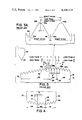
- FIG. 1 is a fragmentary, schematic illustration of the operation of cylindrical through-feed dies in which the threads are formed on the workpiece as it feeds through the dies;
- FIG. 2 is an enlarged, fragmentary section of a cylindrical through-feed die in accordance with this invention in which the spacing or pitch of the crests of the thread form is uniformly maintained along the entire length of the die;
- FIG. 2A is a greatly enlarged, fragmentary section of the die of FIG. 2 illustrating the thread form at the junction of one of the conical end portions and the cylindrical dwell portion in which the pitch at the thread crest is uniformly maintained and an enlarged pitch is provided at such junction at the thread root;
- FIG. 3 is an enlarged fragmentary section of a prior art cylindrical thread rolling die formed by a single point grinding wheel, which is also illustrated;
- FIG. 3A is a greatly enlarged, fragmentary section of the die of FIG. 3 illustrating the junction between one of the conical end portions and the dwell portion where a pitch error exists at the crest of the thread form;
- FIG. 4 is a fragmentary section of a grinding wheel used to form the die of FIG. 2 when such die is provided with a helical thread form;
- FIG. 5 is an enlarged layout of the tooth form of the grinding wheel of FIG. 4 illustrating the various angles and dimensions utilized to establish the thread form;
- FIG. 5A is a table of the angle and dimensional relationships in the layout of FIG. 5 in accordance with this invention.
- FIG. 6 is a fragmentary section of a grinding wheel used to form the die of FIG. 2 when such die is provided with annular teeth;
- FIG. 7 is a greatly enlarged layout of the tooth form of the grinding wheel of FIG. 6 illustrating the various angles and dimensions for establishing a tooth form
- FIG. 7A is a table of the angle and dimensional relationships of the layout of FIG. 7 to incorporate the present invention.
- FIG. 8 is a greatly enlarged view of the fragmentary section of another cylindrical thread profile of the die of FIG. 2 when such die is produced by a grinding wheel having a single final thread form;
- FIG. 8A is a fragmentary view of the grinding wheel used to produce the die of FIG. 8.
- FIG. 1 schematically illustrates the through-feed rolling of a workpiece with cylindrical through-feed thread rolling dies.
- the workpiece 10 as it is rotated by the dies, progressively moves to the right and passes between the dies 11 and 12.
- the dies are mounted on axes which are skewed with respect to the axis of the workpiece in the usual manner.
- this invention is also applicable to systems where the dies are parallel to the axis of the workpiece.
- the dies 11 and 12 are formed with either helical thread forms or annular thread forms.
- Each of the dies is formed with a lead-in taper or ramp portion 13 extending from the entrance end 14 of the dies to a plane or junction at 16.
- a uniform diameter dwell portion 17 extends from the plane 16 to the plane or junction 18.
- An exit taper or ramp 19 extends from the plane 18 to the exit end 21 of the die.
- the lead-in ramp 13 and the exit ramp 19 are conical and intersect the adjacent ends of the cylindrical or dwell portion 17 at the planes or junctions 16 and 18, respectively.
- the workpiece feeds into the dies from the left side thereof as viewed in FIG. 1, and as a given portion of the workpiece moves inwardly along the lead-in ramps 13, a thread is progressively formed on the surface of the workpiece.
- the threads are substantially fully formed and substantially fill the thread form on the dies.
- the thread on the workpiece is only partially formed and the thread forms on the dies are only partially filled.
- the portions of the workpiece 10 continue along the dwell portions 17, where the thread is finished. Because the axes of the dies 11 and 12 are skewed with respect to the axis of the workpiece, there is an hourglass effect which causes the maximum penetration of the thread forms on the dies into the workpiece to occur at approximately the midpoint along the length of the dwell portion. There is substantially no working of the threads as they pass beyond the dwell portion to the exit ramps 19, but the exit ramps are generally utilized to provide a gradual release of the pressure on the workpiece so that the threads are not damaged as they exit from the die.
- the crest spacing or pitch of the threads on the thread rolling dies are uniformly maintained throughout the length of the dies so that a thread shift is not produced at the end of the dwell portion 17 where it joins the two ramps 13 and 19.
- the greatest pressures occur along the crests of the thread forms on the dies, since these portions of the thread forms provide the greatest penetration into the workpiece. Consequently, any shift in pitch or spacing which might exist at the crests has the maximum effect on the threads formed on the workpiece and produces a very high pressure load on the die.
- FIG. 2 is an enlarged, fragmentary section of the die 11.
- such die may be formed with a helical thread form or may be formed with annular thread forms.
- the die 11 is ground so that the spacing or pitch P between the crests of the thread forms is uniformly maintained throughout the lengths of the die even along the junctions 16 and 18 between the dwell and the lead-in taper 13 and the exit taper 19, respectively.
- the pitch or spacing between the crests is illustrated by the distance P.
- the spacing between the root at 24a and the next adjacent root at 24b is greater than the spacing between the roots 24 at locations spaced from such junctions.
- This increased spacing between the roots 24a and 24b is necessary in order to ensure that a uniform spacing is provided between the crests 22 along the entire length of the die.
- a simulat situation exists at the junction 18, wherein an increased spacing is provided between the root 24c and the root at 24d.
- FIG. 2A is a greatly enlarged view of the threads at the junction 16.
- the thread at the left end of the dwell portion is illustrated along with the first threads along the lead-in ramp 13.
- the projection of the thread forms of the dwell portion are illustrated by dotted line as they would exist if it were not for the existence of the tapered or conical ramp portion.
- the last thread crest 22a of the dwell is spaced from the last root 24a by a distance equal to P/2, or one-half the pitch distance.
- the next root 24b is at a lower level than it would be if it were not for the taper. If it were not for the taper, the next root would be located at 24h, as indicated by the dotted line projection of the thread forms along the dwell portion.
- the root at 24b is at a lower level than the projected root at 24h, it is displaced laterally from the plane 31 by a distance d, where the plane 31 is spaced from the crest 22A by P/2, or one-half the pitch.
- the crest at 22b which is the first crest located on the lead-in taper 13, is spaced from the crest 22a by an exact pitch and is located in direct alignment with the projected crest 22h.
- the exit pitch is again established at the roots, as illustrated between 24b and 24e.
- the variation in the spacing between the root exists only between the first root on the dwell and the adjacent root on the lead-in ramp. It should be recognized that for purposes of illustration, the ramp angle is exaggerated in the drawing and that the displacement error d at the roots is of a relatively small magnitude.
- a similar enlarged spacing is provided at the junction 18 between the dwell 17 and the exit taper where the spacing between the roots at 24c and 24d is slightly larger than the spacing between the roots along the remainder of the die.
- FIG. 3 illustrates a prior art through-feed cylindrical thread rolling die 41 of the type formed with a single point grinding wheel 42 having a single thread form 43 on its periphery.
- Such die 41 is provided with a dwell portion 44 of uniform diameter between the two planes 46 and 47 at the ends of the dwell portion.
- a conical lead-in ramp 48 is provided between the plane 46 and the entrance end 50 of the die.
- a conical exit portion 49 is provided between the plane 47 and the exit end 51 of the die.
- the grinding wheel 42 is indexed along the die in a manner which is timed with the rotation of the die blank so that the grinding wheel moves axially with respect to the die a distance equal to one lead of the thread being formed each time the work rotates through one revolution.
- This operation produces a uniform spacing of the roots 52 of the thread, where the spacing is equal to one pitch distance, throughout the entire length of the die.
- a lead error occurs at the junctions between the dwell portion and the lead-in and exit ramps at the crests of such threads where the crest 53a is spaced from the crest 53b by a distance equal to less than one pitch.
- FIG. 3A is a greatly enlarged view of the junction at the plane 46 between the dwell 44 and the lead-in ramp 48.
- the root 52a is the root formed by the grinding wheel at the end of the dwell 44.
- the adjacent root 52b is ground to a depth greater than the root 52a, as illustrated by the spacing between the dotted projected root 52h.
- the spacing of the two roots 52a and 52b is an exact pitch because the root is formed by the extremity of the wheel 42 and the wheel is indexed in exact pitch amount.
- the crest at 53a is spaced to the right from the location 53h where the projected crest would have occurred, as indicated by the dotted lines, and the spacing between the crest at 53a and the crest at 53b is less than an exact pitch by an error d. Consequently, with the prior art die of FIG. 3, a thread shift is forced in the workpiece as the workpiece progresses across the junction between the lead-in portion of the die and the exit dwell of the die. A similar shift occurs at the junction between the dwell portion 44 and the exit portion 49, but since the pressure on the die is being relieved at such location, it does not normally produce as much of a problem.
- the prior art die has a uniform pitch spacing between the roots of the thread forms on the die and a uniform crest spacing except at the junction of the lead-in and exit portions of the die with the dwell portion thereof. At such junctions, the spacing at the crest is less than the proper spacing and an inferior die is provided. Further, such die produces excessive pressure at the location of the error, which results in wear and breakage.
- FIG. 4 illustrates a grinding wheel for use in the manufacture of a die incorporating this invention, as illustrated in FIG. 2, when the die is formed with helically arranged threads.
- This grinding wheel is shaped with three sections to form the related sections on the die.
- the wheel 60 is provided with a first portion 61 extending from the right end of the wheel at 62 to a junction plane 63.
- the portion 61 is formed with a conical shape and is used to grind the lead-in taper 13 of the die of FIG. 2.
- Extending from the junction plane 63 to a junction plane 64 is a dwell portion 66.
- the remainder of the wheel extending from the plane 64 to the end face 67 is a taper 68 used to grind the exit ramp or taper 19.
- the grinding wheel it is preferable to form the grinding wheel so that the dwell 66 extends from one root 69 to another root 71, so that the dwell on the die will end at a thread crest. Further, the length of the various portions should be sufficient to provide a number of thread forms on each portion at least equal to the number of starts required on the die. Since a die is formed with a lead which is greater than the pitch by some multiple, the threads have more than one start.
- the grinding wheel is formed so that the roots of the thread forms produced thereon are spaced apart by exactly one pitch throughout the entire length of the wheel. With such a structure, the pitch error occurring at the junctions between the dwell portions of the two tapered portions will exist at the crests of the threads on the wheel, with all of the remaining crests properly spaced by one exact pitch.
- the grinding wheel 62 When the grinding wheel 62 is used to grind a die 11, the wheel is positioned with respect to the die blank at the proper skewed angle so that the annular thread form on the wheel will produce the desired helical thread form on the die.
- the grinding is accomplished by starting one end 14 of the die and the wheel is fed across the die face while the wheel is withdrawn progressively the proper amount to cause the tapered portion 61 to form the lead-in taper 13.
- the plane 63 reaches the position opposite the plane 16 on the die, the retraction is terminated and the grinding wheel feeds across the dwell portion forming the threads on the dwell portion 17 with the dwell portion 66 of the grinding wheel.
- the grinding wheel of FIG. 4 should be dimensioned as illustrated in FIG. 5, and the dimensions are interrelated as set forth in the Table of FIG. 5A.
- FIG. 5 only a portion of the dwell 66 and only portions of the tapered sections 61 and 68 are illustrated, but the remaining portions in an actual grinding wheel should conform to the illustrated dimensions.
- the dimension A is the pitch or spacing between adjacent thread form roots and is accurately maintained for all portions of the annular thread form. This dimension is established by the thread to be produced in the manner known to those skilled in the art.
- the angle B is the angle of the finish or exit ramp required for the particular die.
- the dimension F is the dimension of the flat and is determined by the thread to be rolled.
- the angle H is determined by the angle of the corresponding ramp surface.
- the angle N is determined by the thread form to be produced.
- the lead adjustment K is similarly related to the angle H and is established in accordance with the formulas of the table.
- a crush roll is developed which will produce in the grinding wheel the thread forms as illustrated in FIG. 5. With such grinding wheel, the proper thread forms are then established on the die, as described above.
- the grinding wheel In producing a die having annular thread forms thereon with a single multigroove grinding wheel 76, the grinding wheel itself has at least the same width as the die and the entire length die is ground simultaneously. In such instance, the thrad forms on the grinding wheel are an exact mirror image of the thread forms to be produced on the die.
- Such grinding wheel illustrated in FIG. 6 will necessarily then be concave in shape, having a central dwell portion 17' convoluted to be a mirror of the dwell portion 17, a lead-in taper portion 13' convoluted to be a mirror of a starting or lead-in ramp 13, and an exit taper portion 19' which is tapered and convoluted to be a mirror of the exit ramp 19.
- the spacing between the roots of the thread forms on the grinding wheel must be uniformly maintained to ensure that the spacing between the crests of the thread forms on the die are uniformly maintained.
- the grinding wheel 76 is concave to produce the required convex die.
- FIGS. 7 and 7A are respectively greatly enlarged dimensional views of the grinding wheel 76 having corresponding dimensions to the dimensions illustrated in FIG. 5.
- the various interrelationships are as set forth in the Table of FIG. 7A. Since such relationships are quite similar to those set forth in FIG. 5A and discussed above, they are not repeated herein.
- the grinding of a die with a grinding wheel 76 dimensioned as illustrated again produces a die where the spacing of the crests between the thread forms is uniformly maintained throughout the length of the die and the lead adjustment required to establish such uniform spacing at the crests exists at the roots at the junctions between the dwell portion and the two ramp portions of the die.
- FIG. 8 is a greatly enlarged view of the thread profile of the die of FIG. 2, when produced by a grinding wheel having a single female thread form, as illustrated in FIG. 8A.
- Such wheel 81 illustrated in FIG. 8A is provided with a single female thread form 82 and extends to flats 83.
- the wheel is preferably relieved on the sides at 84 by any angle selected to provide clearance with the adjacent parts on the die.
- the grinding wheel 81 When the grinding wheel 81 is used to produce a die having annular thread forms thereon, the grinding wheel is fed in an appropriate amount to form the thread form at a given point on the die and is indexed laterally a distance equal to one pitch between each cut. Because the crest of the thread form on the die 11 is produced by the root on the grinding wheel, such indexing of the grinding wheel produces a thread form wherein a uniform spacing is provided at the crests throughout the length of the die. However, along the lead-in and exit ramps, the roots are provided with a step 86 because of the difference in depth of each cut along the ramp sections and the pitch adjustment or error is automatically developed at the root of the thread.
- the grinding wheel is indexed along the length of the die a distance equal to one lead during each revolution of the die and is fed in or out, usually by a cam, to properly form the lead-in and exit ramps.
- the resulting die is provided with an accurate spacing between the crests of the thread forms on the die to eliminate any thread shift during the use of the die in producing threads on a workpiece. Because these threads shifts do not occur, the existence of drunken threads, excessive pressures on the die, and excessive die breakage are virtually eliminated.
Abstract
Description
Claims (6)
Priority Applications (1)
| Application Number | Priority Date | Filing Date | Title |
|---|---|---|---|
| US06/314,688 US4408418A (en) | 1980-01-21 | 1981-10-26 | Method of forming through-feed cylindrical thread rolling dies |
Applications Claiming Priority (2)
| Application Number | Priority Date | Filing Date | Title |
|---|---|---|---|
| US11371980A | 1980-01-21 | 1980-01-21 | |
| US06/314,688 US4408418A (en) | 1980-01-21 | 1981-10-26 | Method of forming through-feed cylindrical thread rolling dies |
Related Parent Applications (1)
| Application Number | Title | Priority Date | Filing Date |
|---|---|---|---|
| US11371980A Division | 1980-01-21 | 1980-01-21 |
Publications (1)
| Publication Number | Publication Date |
|---|---|
| US4408418A true US4408418A (en) | 1983-10-11 |
Family
ID=26811390
Family Applications (1)
| Application Number | Title | Priority Date | Filing Date |
|---|---|---|---|
| US06/314,688 Expired - Lifetime US4408418A (en) | 1980-01-21 | 1981-10-26 | Method of forming through-feed cylindrical thread rolling dies |
Country Status (1)
| Country | Link |
|---|---|
| US (1) | US4408418A (en) |
Cited By (11)
| Publication number | Priority date | Publication date | Assignee | Title |
|---|---|---|---|---|
| DE3428692A1 (en) * | 1984-08-03 | 1986-02-13 | Kamax-Werke Rudolf Kellermann Gmbh & Co Kg, 3360 Osterode | Method for the production of tools for the production of threads by thread rolling |
| US5519071A (en) * | 1991-11-12 | 1996-05-21 | Ivoclar Ag | Dental cement |
| US5943904A (en) * | 1995-03-08 | 1999-08-31 | Ingersoll Cutting Tool Company | Thread-rolling die |
| US6035744A (en) * | 1997-11-04 | 2000-03-14 | Schwarzkopt Technologies Corp. | Method for the production of a cutting insert for thread cutting |
| CN1125699C (en) * | 2000-12-01 | 2003-10-29 | 上海柴油机股份有限公司 | Technology for machining top arc of teeth for thread rolling die |
| US20040077414A1 (en) * | 2001-03-30 | 2004-04-22 | Anderson William Carl | Apparatus for coupling male threads to female threads |
| US20100329806A1 (en) * | 2009-06-25 | 2010-12-30 | Harry Ellis | Form tap and method of making such |
| US20110085867A1 (en) * | 2009-10-09 | 2011-04-14 | Harry Leroy Ellis | Form Tap Having a Plurality of Lobes |
| US20150258600A1 (en) * | 2012-10-08 | 2015-09-17 | Shanghai Pan-China Fastening System Co., Ltd. | Rolling head for rolling pipe threads, apparatus and pipe column blank machined by the apparatus |
| CN105317807A (en) * | 2015-11-27 | 2016-02-10 | 宁波敏达机电有限公司 | Tapered thread bolt and processing tooth plate thereof |
| JP2022175327A (en) * | 2021-05-13 | 2022-11-25 | ユニオンツール株式会社 | Rolling die |
Citations (9)
| Publication number | Priority date | Publication date | Assignee | Title |
|---|---|---|---|---|
| US1702160A (en) * | 1927-01-21 | 1929-02-12 | Einar A Hanson | Method of and apparatus for grinding convoluted members |
| FR1100772A (en) * | 1954-05-19 | 1955-09-23 | Method and device for trimming the threads of die pads | |
| US3023546A (en) * | 1957-07-03 | 1962-03-06 | Beck Alfred | Machine for making threadcutting tools |
| US3347114A (en) * | 1966-08-24 | 1967-10-17 | Balax Inc | Method of making taps |
| US3561171A (en) * | 1968-08-14 | 1971-02-09 | Balax Inc | Swaging taps with uniform crest width and method of manufacture thereof |
| DE2046287A1 (en) * | 1970-09-19 | 1972-03-23 | Doerrenberg & Co Praezisionswe | Thread rolling roller |
| US3651678A (en) * | 1968-11-06 | 1972-03-28 | Reed Rolled Thread Die Co | Truncated through feeding thread rolling die |
| SU553091A1 (en) * | 1972-12-25 | 1977-04-05 | The method of grinding the thread on the intake part of taps, rolling | |
| US4119079A (en) * | 1976-03-22 | 1978-10-10 | Erwin Junker | Roller for producing a profile on a grinding wheel |
-
1981
- 1981-10-26 US US06/314,688 patent/US4408418A/en not_active Expired - Lifetime
Patent Citations (9)
| Publication number | Priority date | Publication date | Assignee | Title |
|---|---|---|---|---|
| US1702160A (en) * | 1927-01-21 | 1929-02-12 | Einar A Hanson | Method of and apparatus for grinding convoluted members |
| FR1100772A (en) * | 1954-05-19 | 1955-09-23 | Method and device for trimming the threads of die pads | |
| US3023546A (en) * | 1957-07-03 | 1962-03-06 | Beck Alfred | Machine for making threadcutting tools |
| US3347114A (en) * | 1966-08-24 | 1967-10-17 | Balax Inc | Method of making taps |
| US3561171A (en) * | 1968-08-14 | 1971-02-09 | Balax Inc | Swaging taps with uniform crest width and method of manufacture thereof |
| US3651678A (en) * | 1968-11-06 | 1972-03-28 | Reed Rolled Thread Die Co | Truncated through feeding thread rolling die |
| DE2046287A1 (en) * | 1970-09-19 | 1972-03-23 | Doerrenberg & Co Praezisionswe | Thread rolling roller |
| SU553091A1 (en) * | 1972-12-25 | 1977-04-05 | The method of grinding the thread on the intake part of taps, rolling | |
| US4119079A (en) * | 1976-03-22 | 1978-10-10 | Erwin Junker | Roller for producing a profile on a grinding wheel |
Cited By (17)
| Publication number | Priority date | Publication date | Assignee | Title |
|---|---|---|---|---|
| DE3428692A1 (en) * | 1984-08-03 | 1986-02-13 | Kamax-Werke Rudolf Kellermann Gmbh & Co Kg, 3360 Osterode | Method for the production of tools for the production of threads by thread rolling |
| US5519071A (en) * | 1991-11-12 | 1996-05-21 | Ivoclar Ag | Dental cement |
| US5943904A (en) * | 1995-03-08 | 1999-08-31 | Ingersoll Cutting Tool Company | Thread-rolling die |
| US6035744A (en) * | 1997-11-04 | 2000-03-14 | Schwarzkopt Technologies Corp. | Method for the production of a cutting insert for thread cutting |
| CN1125699C (en) * | 2000-12-01 | 2003-10-29 | 上海柴油机股份有限公司 | Technology for machining top arc of teeth for thread rolling die |
| US20040077414A1 (en) * | 2001-03-30 | 2004-04-22 | Anderson William Carl | Apparatus for coupling male threads to female threads |
| US6959553B2 (en) * | 2001-03-30 | 2005-11-01 | General Electric Company | Systems and methods for designing threads of turbine engine connectors |
| US8602841B2 (en) | 2009-06-25 | 2013-12-10 | Harry Leroy Ellis | Form tap and method of making such |
| US20100329806A1 (en) * | 2009-06-25 | 2010-12-30 | Harry Ellis | Form tap and method of making such |
| US20110085867A1 (en) * | 2009-10-09 | 2011-04-14 | Harry Leroy Ellis | Form Tap Having a Plurality of Lobes |
| US8602696B2 (en) | 2009-10-09 | 2013-12-10 | Harry Leroy Ellis | Form tap having a plurality of lobes |
| US20150258600A1 (en) * | 2012-10-08 | 2015-09-17 | Shanghai Pan-China Fastening System Co., Ltd. | Rolling head for rolling pipe threads, apparatus and pipe column blank machined by the apparatus |
| US10464119B2 (en) * | 2012-10-08 | 2019-11-05 | Shanghai Pan-China Fastening System Co., Ltd. | Rolling head for rolling pipe threads, apparatus and pipe column blank machined by the apparatus |
| CN105317807A (en) * | 2015-11-27 | 2016-02-10 | 宁波敏达机电有限公司 | Tapered thread bolt and processing tooth plate thereof |
| CN105317807B (en) * | 2015-11-27 | 2016-08-17 | 宁波敏达机电有限公司 | Band taper thread bolt and processing dental lamina thereof |
| JP2022175327A (en) * | 2021-05-13 | 2022-11-25 | ユニオンツール株式会社 | Rolling die |
| JP7266062B2 (en) | 2021-05-13 | 2023-04-27 | ユニオンツール株式会社 | rolling dies |
Similar Documents
| Publication | Publication Date | Title |
|---|---|---|
| US4408418A (en) | Method of forming through-feed cylindrical thread rolling dies | |
| US2308891A (en) | Method and apparatus for gear generation | |
| US2285133A (en) | Cutter for and method of cutting gears | |
| US3561171A (en) | Swaging taps with uniform crest width and method of manufacture thereof | |
| US3580027A (en) | Gear rolling | |
| EP0521866B1 (en) | Process for producing face hobbed bevel gears with toe relief | |
| US6708544B2 (en) | Thread rolling die and process for the production thereof | |
| GB2067444A (en) | Through-feed cylindrical thread rolling dies | |
| JP5042931B2 (en) | Rolled bolt | |
| US4666348A (en) | Cutter for thread rolling dies | |
| US2298471A (en) | Gear finishing | |
| US2346807A (en) | Method of cutting gears | |
| US1996987A (en) | Rotary gear cutting tool | |
| US2183689A (en) | Thread forming mechanism | |
| US3945272A (en) | Thread-rolling method, thread-rolling dies, and method of manufacturing the dies | |
| US3818749A (en) | Thread rolling dies and method of manufacturing same | |
| US2864153A (en) | Hob | |
| US2357153A (en) | Method of cutting gears | |
| US2392172A (en) | Broach | |
| US4573376A (en) | Method of producing thread rolling die | |
| JP4201647B2 (en) | Rolled flat dies, rolling dies and manufacturing method thereof | |
| US3371396A (en) | Cutter for milling gears and the like | |
| JPH0137800Y2 (en) | ||
| US2146232A (en) | Hob | |
| US2617331A (en) | Gear finishing |
Legal Events
| Date | Code | Title | Description |
|---|---|---|---|
| STCF | Information on status: patent grant |
Free format text: PATENTED CASE |
|
| AS | Assignment |
Owner name: COLT INDUSTRIES INC., 430 PARK AVE., NEW YORK, N.Y Free format text: ASSIGNMENT OF ASSIGNORS INTEREST.;ASSIGNOR:COLT INDUSTRIES OPERATING CORP.;REEL/FRAME:004658/0309 Effective date: 19861217 Owner name: COLT INDUSTRIES INC., A CORP. OF PA.,NEW YORK Free format text: ASSIGNMENT OF ASSIGNORS INTEREST;ASSIGNOR:COLT INDUSTRIES OPERATING CORP.;REEL/FRAME:004658/0309 Effective date: 19861217 |
|
| MAFP | Maintenance fee payment |
Free format text: PAYMENT OF MAINTENANCE FEE, 4TH YEAR, PL 96-517 (ORIGINAL EVENT CODE: M170); ENTITY STATUS OF PATENT OWNER: LARGE ENTITY Year of fee payment: 4 |
|
| MAFP | Maintenance fee payment |
Free format text: PAYMENT OF MAINTENANCE FEE, 8TH YEAR, PL 96-517 (ORIGINAL EVENT CODE: M171); ENTITY STATUS OF PATENT OWNER: LARGE ENTITY Year of fee payment: 8 |
|
| AS | Assignment |
Owner name: COLTEC INDUSTRIES, INC. Free format text: CHANGE OF NAME;ASSIGNOR:COLT INDUSTRIES INC.;REEL/FRAME:006144/0197 Effective date: 19900503 |
|
| AS | Assignment |
Owner name: BANKERS TRUST COMPANY, NEW YORK Free format text: SECURITY INTEREST;ASSIGNOR:COLTEC INDUSTRIES INC.;REEL/FRAME:006080/0224 Effective date: 19920401 |
|
| MAFP | Maintenance fee payment |
Free format text: PAYMENT OF MAINTENANCE FEE, 12TH YEAR, LARGE ENTITY (ORIGINAL EVENT CODE: M185); ENTITY STATUS OF PATENT OWNER: LARGE ENTITY Year of fee payment: 12 |
|
| FEPP | Fee payment procedure |
Free format text: PAYOR NUMBER ASSIGNED (ORIGINAL EVENT CODE: ASPN); ENTITY STATUS OF PATENT OWNER: LARGE ENTITY |
|
| AS | Assignment |
Owner name: COLTEC INDUSTRIES, INC., NORTH CAROLINA Free format text: RELEASE OF SECURITY INTEREST;ASSIGNOR:BANKER'S TRUST COMPANY;REEL/FRAME:012865/0638 Effective date: 20010731 |