US4388624A - Radar antenna incorporating elements radiating a pseudo-omnidirectional pattern - Google Patents
Radar antenna incorporating elements radiating a pseudo-omnidirectional pattern Download PDFInfo
- Publication number
- US4388624A US4388624A US06/199,992 US19999280A US4388624A US 4388624 A US4388624 A US 4388624A US 19999280 A US19999280 A US 19999280A US 4388624 A US4388624 A US 4388624A
- Authority
- US
- United States
- Prior art keywords
- dipoles
- pattern
- antenna
- reflector
- transmission
- Prior art date
- Legal status (The legal status is an assumption and is not a legal conclusion. Google has not performed a legal analysis and makes no representation as to the accuracy of the status listed.)
- Expired - Lifetime
Links
- 208000032369 Primary transmission Diseases 0.000 claims 2
- 208000032370 Secondary transmission Diseases 0.000 claims 2
- 230000005855 radiation Effects 0.000 description 8
- 238000010586 diagram Methods 0.000 description 4
- 230000001629 suppression Effects 0.000 description 4
- RYGMFSIKBFXOCR-UHFFFAOYSA-N Copper Chemical compound [Cu] RYGMFSIKBFXOCR-UHFFFAOYSA-N 0.000 description 1
- 238000010276 construction Methods 0.000 description 1
- 229910052802 copper Inorganic materials 0.000 description 1
- 239000010949 copper Substances 0.000 description 1
- 230000001419 dependent effect Effects 0.000 description 1
- 238000009434 installation Methods 0.000 description 1
- 238000000034 method Methods 0.000 description 1
- 230000001681 protective effect Effects 0.000 description 1
- 230000006641 stabilisation Effects 0.000 description 1
- 238000011105 stabilization Methods 0.000 description 1
- 230000001960 triggered effect Effects 0.000 description 1
Images


Classifications
-
- H—ELECTRICITY
- H01—ELECTRIC ELEMENTS
- H01Q—ANTENNAS, i.e. RADIO AERIALS
- H01Q21/00—Antenna arrays or systems
- H01Q21/28—Combinations of substantially independent non-interacting antenna units or systems
Definitions
- the present invention relates to a radar antenna incorporating elements radiating a pseudo-omnidirectional pattern.
- the invention is applicable on the one hand to an antenna for primary radar ensuring the side lobe blanking (S.L.B.) function for the directional pattern, which consists of covering these side lobes of the directional radiation pattern emitted by the primary source of the radar with a pseudo-omnidirectional radiation pattern, whose level is higher than that of the side lobes to be covered.
- the invention is also applicable to a common antenna for primary and secondary radars having an interrogation system of the IFF type and which also ensures the side lobe suppression (S.L.S.) function of the directional pattern.
- An antenna for filling the primary radar function has a reflector supplied in such a way that it radiates energy for the purpose of detecting a target.
- this target has a sufficiently high interference level to cover the side lobes of the directional pattern radiated by the antenna particular interest is attached to the answer of this target in the axis of the major lobe of the directional pattern by attempting to mask the interference of the target by a pseudo-omnidirectional pattern.
- a source is placed above the antenna reflector, for example a horn, which radiates such a pattern.
- this type of source has the disadvantage of being heavy and complicated.
- common antenna for primary and secondary radars is understood to mean a single reflector supplied so as to ensure the direction function of a primary radar and which is also able to emit an interrogation signal from said target and to receive the answer from its on-board transponder, i.e. what is called the secondary radar function.
- the beam carrying the interrogation is directional, interrogating in the direction where the aircraft has been detected.
- the responder of the interrogated aircraft could be triggered by the side lobes of the interrogation pattern, whose level may be relatively high compared with that of the major lobe.
- this single antenna is supplemented by so-called control means incorporating radiating elements acting at the reception of the interrogation by the interrogated responder and at the reception of the answer from the latter by the receiver in question. They radiate in accordance with a quasi-omnidirectional pattern, whose level is such that it covers the side lobes of the pattern radiated by the main antenna.
- control means for realizing this control diagram must be such that the gain of the associated control channels is higher than that of the interrogation and reception channels in the angular areas comprising the side lobes of the directional interrogation pattern, but much lower in the direction of their major lobe.
- control means are either physically independent of the main antenna constituted by an omnidirectional antenna placed alongside the main antenna, or are dependent, the control function being fulfilled by the secondary radar antenna supplied for a given time so as to give a radiation pattern of the difference type, whilst the pattern by which the interrogation takes place is a sum pattern.
- the radiation pattern of the control means does not completely fulfill its function, either because it is not totally omnidirectional, or because certain high level side lobes of the main directional pattern are not covered and also because in certain cases the major lobe, whose level is a little low, is liable to be smothered by the omnidirectional pattern.
- the control patterns can be disturbed by certain external installations such as, for example, the radomes under which the antennas are placed.
- the object of the invention is to obviate these disadvantages and provide an antenna having elements which radiate a pseudo-omnidirectional pattern.
- the present invention therefore relates to a radar antenna comprising a reflector illuminated by one or more transmission-reception sources, at least one of them radiating a directional pattern and having a system of elements radiating a pattern of the pseudo-omnidirectional type with a crevasse in the direction of the major lobe of the directional pattern radiated by one of the sources, wherein the system of radiating elements is constituted by one or more groups of two dipoles placed above and in the vicinity of the reflector, symmetrically with respect to the plane of symmetry thereof, the distance between two consecutive dipoles being between 0.5 and 0.8 times the wavelength at the centre frequency of the operating band, in such a way that they radiate towards the front thereof and independently thereof produce a pseudo-omnidirectional pattern.
- the invention can use an antenna for a primary radar which ensures the side lobe blanking function. It can also use a common antenna for primary and secondary radars which also fulfills the side lobe suppression function.
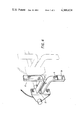
- FIG. 1 a diagrammatic view of an antenna in the plane of symmetry ⁇ of the reflector, having elements radiating a pseudo-omnidirectional diagram according to the invention.
- FIG. 2 a diagrammatic representation of a non-limitative embodiment of elements radiating a pseudo-omnidirectional diagram according to the invention.
- FIG. 3 the antenna radiation diagrams incorporating radiating elements according to the invention in the bearing plane.
- FIG. 4 an internal view of a conventional dipole antenna used in FIGS. 1 and 2.
- FIG. 1 shows in diagrammatic manner an antenna comprising a reflector 1 having a random configuration, illuminated by a primary source 2 placed in front of it and radiating a directional pattern.
- the elements radiating a pseudo-omnidirectional control pattern are constituted by a group of two detachable dipoles 3 having upper legs 13 and lower legs 9 as shown in FIGS. 1 and 2 of the full wave or half-wave type arranged in juxtaposed manner just above the antenna reflector 1 in the median plane thereof.
- the position of the dipoles is such that they free the reflectors both for correctly radiating without being disturbed by the same and for not forming a shadow relative to the radiation from the primary source 2. However, it is accepted that they can occult reflector 1 by the lower legs 9, as shown in FIG. 1.
- the distance between the two dipoles 3 is between 0.5 and 0.8 times the wavelength of the centre frequency of the operating band so as to obtain the desired pseudo-omnidirectional pattern, i.e. covering the side lobes of the directional pattern, but having a crevasse centred on the direction of the major lobe of the same pattern.
- the two dipoles are arranged symmetrically with respect to the plane of symmetry ⁇ of the reflector. They are supplied in phase opposition by means of two power dividers 4 which are also detachable and radiate directly without a reflector to cover the side lobes of the directional pattern with a 360° aperture.
- their pseudo-omnidirectional radiation pattern has a crevasse symmetrical to the main crevasse in the direction of the major lobe of the directional pattern.
- the side lobe suppression function can also be ensured by several groups of dipole pairs distributed symmetrically on either side of the plane of symmetry ⁇ of the reflector 1 in accordance with a linear array as illustrated in FIG. 2 which shows, for example, an additional pair of dipoles 23 and 23'.
- FIG. 2 shows, for example, an additional pair of dipoles 23 and 23'.
- An antenna formed in this way can be used for a primary radar having a side lobe blanking function ensured by dipoles 3, which radiate a pseudo-omnidirectional pattern having a crevasse centred on the major lobe of the directional pattern of the primary source 2.
- a source 5 constituted for example by two dipoles of the full or half-wave type provided with appropriate reflectors. These dipoles are energized in phase by means of a not shown, conventional, power divider and two coaxial connecting cables 7. These dipoles radiate the directional pattern of the reception interrogation channel of the secondary radar.
- the dipoles 3 radiating the pseudo-omnidirectional pattern of the control channel whose crevasse coincides with the major lobe of the directional pattern of the interrogation channel ensure the side lobe suppression function of the secondary radar, to the extent that their pattern covers all the interrogation pattern, except in the direction of the major lobe.
- FIG. 1 shows a radome 8 and stabilization devices 80 for the antenna reflector 1.
- Reflector 1 is located on the detachable part 81 of a frame 82 having a fixing system 83. This makes it possible to fold back the antenna, by tilting reflector 1 towards frame 82.
- dipoles 3 and dividers 4 are detachable provides the advantage that they can be retracted or folded back when it is desired to fold back the antenna, e.g. in the case of transportation.
- FIG. 2 shows an example of an element radiating a pseudo-omnidirectional pattern used in an antenna according to the invention.
- This element comprises two conventional dipoles 3, of the half-wave or full wave type, which are juxtaposed in parallel on a fixing rod 10. They are constituted by a coaxial base 11, an open coaxial line 12 serving as an adapter and symmetrizer and two radiating legs 9, 13 for each of the dipoles 3 as detailed in FIGS. 1 and 4, whose length is generally equal to quarter or half the operating wavelength of the system.
- These two dipoles are connected to a conventional power divider 14 by coaxial cables 15, whilst another coaxial connecting cable 16 connects the power divider and the antenna reflector.
- Power divider 14 is fixed to a rod 17 forming a T with the rod 10.
- the dipoles 23 and 23' are mounted on the rod 10. It is noted that the curvature of the rod 10 must conform to the antenna reflector structure to ensure that each pair of dipoles are distributed symmetrically with respect to the plane of symmetry of the reflector.
- Three fixing means 18, such as screws, can be provided for fixing the radiating element to the antenna reflector. The fact that these radiating elements are constructed independently of the reflector and have means for fixing to the latter makes it possible to set them down or retract them during movements of the antenna, which then has reduced overall dimensions.
- the FIG. 2 further shows a weather protective plastic covering 29 for each dipole.
- dipoles are not intended to be in any way limitative and it is possible to envisage the use of dipoles obtained by the photogravure of a copper sheet on a dielectric wafer, using much the same procedure as that employed for printed circuits.
- FIG. 3 shows the pseudo-omnidirectional radiation pattern emitted by the elements associated with an antenna according to the invention, as well as a typical directional pattern. Both of these patterns are located in the bearing plane designated by the abscissa axis ⁇ (bearing angle) and ordinate axis G (gain in dB).
- the directional pattern 19 is that emitted by an antenna for primary radar or that emitted by the interrogation-reception channel of a common antenna for primary and secondary radar.
- the pseudo-omnidirectional pattern 20 radiated by the elements according to the invention covers the side lobes 22 of the directional pattern, except in the direction of the major lobe of the latter where it has a crevasse 21. As has been stated hereinbefore there is also a crevasse, but with a much smaller amplitude, in the axis of the major lobe, but in the opposite direction due to the power supply for the dipoles.
- an IFF antenna according to the invention must have a good covering or overlap level and processing arc widths which are compatible with the large angular aperture generally required in elevation. This makes it necessary to have a high omnidirectionality of the pattern, outside the axial region.
- FIG. 4 details a conventional dipole used as any of the dipoles 3 or 23 and 23' in FIGS. 1 and 2.
- Power is supplied to the leg 9 through lead 30 from a coaxial connector 32 with leg 13 being the ground or common feed from a coaxial cable such as 15 in FIG. 2.
- a radar antenna has been described hereinbefore having elements radiating a pseudo-omnidirectional pattern.
Landscapes
- Variable-Direction Aerials And Aerial Arrays (AREA)
- Radar Systems Or Details Thereof (AREA)
- Aerials With Secondary Devices (AREA)
Applications Claiming Priority (2)
| Application Number | Priority Date | Filing Date | Title |
|---|---|---|---|
| FR7926609A FR2469015A1 (fr) | 1979-10-26 | 1979-10-26 | Antenne radar comportant des elements rayonnant un diagramme pseudo-omnidirectionnel |
| FR7926609 | 1979-10-26 |
Publications (1)
| Publication Number | Publication Date |
|---|---|
| US4388624A true US4388624A (en) | 1983-06-14 |
Family
ID=9231078
Family Applications (1)
| Application Number | Title | Priority Date | Filing Date |
|---|---|---|---|
| US06/199,992 Expired - Lifetime US4388624A (en) | 1979-10-26 | 1980-10-23 | Radar antenna incorporating elements radiating a pseudo-omnidirectional pattern |
Country Status (3)
| Country | Link |
|---|---|
| US (1) | US4388624A (enExample) |
| EP (1) | EP0028185A1 (enExample) |
| FR (1) | FR2469015A1 (enExample) |
Cited By (4)
| Publication number | Priority date | Publication date | Assignee | Title |
|---|---|---|---|---|
| US6067051A (en) * | 1998-12-23 | 2000-05-23 | Terk Technologies, Inc. | Apparatus and method of mounting VHF/UHF antenna assembly on satellite dish antenna |
| EP1014488A3 (de) * | 1998-12-21 | 2001-06-13 | Howaldtswerke-Deutsche Werft Ag | Antennenanordnung für Satellitenkommunikationsanlagen auf Schiffen und U-Booten |
| US6366252B1 (en) | 2000-07-24 | 2002-04-02 | Neil D. Terk | Method and apparatus for mounting an auxiliary antenna to a reflector antenna |
| US10318903B2 (en) | 2016-05-06 | 2019-06-11 | General Electric Company | Constrained cash computing system to optimally schedule aircraft repair capacity with closed loop dynamic physical state and asset utilization attainment control |
Citations (3)
| Publication number | Priority date | Publication date | Assignee | Title |
|---|---|---|---|---|
| US2846678A (en) * | 1955-06-09 | 1958-08-05 | Sanders Associates Inc | Dual frequency antenna |
| US3445850A (en) * | 1965-11-08 | 1969-05-20 | Canoga Electronics Corp | Dual frequency antenna employing parabolic reflector |
| FR2315181A1 (fr) * | 1975-06-20 | 1977-01-14 | Thomson Csf | Dipole rayonnant pour reflecteur, plus particulierement utilise dans une antenne commune pour radar primaire et radar secondaire avec moyens de controle de l'interrogation |
Family Cites Families (6)
| Publication number | Priority date | Publication date | Assignee | Title |
|---|---|---|---|---|
| US2653238A (en) * | 1945-10-26 | 1953-09-22 | Kenneth T Bainbridge | Dual frequency antenna |
| US2966675A (en) * | 1957-10-23 | 1960-12-27 | Stewart Warner Corp | Radar beacon system with side lobe suppression |
| BE622184A (enExample) * | 1961-09-06 | |||
| DE2139216C3 (de) * | 1971-08-05 | 1980-06-12 | Siemens Ag, 1000 Berlin Und 8000 Muenchen | Richtantennenanordnung, bestehend aus einem Hauptreflektorspiegel und zwei Primärstrahlersystemen und Verfahren zur Herstellung einer dielektrischen Reflektorplatte |
| FR2284997A1 (fr) * | 1974-09-13 | 1976-04-09 | Thomson Csf | Antenne commune pour radar primaire et radar secondaire avec moyens de controle de l'interrogation |
| DE2513611A1 (de) * | 1975-03-27 | 1976-10-07 | Licentia Gmbh | Kombinierte radarantenne fuer primaer- und sekundaer-radarbetrieb |
-
1979
- 1979-10-26 FR FR7926609A patent/FR2469015A1/fr active Granted
-
1980
- 1980-10-17 EP EP80401480A patent/EP0028185A1/fr not_active Withdrawn
- 1980-10-23 US US06/199,992 patent/US4388624A/en not_active Expired - Lifetime
Patent Citations (3)
| Publication number | Priority date | Publication date | Assignee | Title |
|---|---|---|---|---|
| US2846678A (en) * | 1955-06-09 | 1958-08-05 | Sanders Associates Inc | Dual frequency antenna |
| US3445850A (en) * | 1965-11-08 | 1969-05-20 | Canoga Electronics Corp | Dual frequency antenna employing parabolic reflector |
| FR2315181A1 (fr) * | 1975-06-20 | 1977-01-14 | Thomson Csf | Dipole rayonnant pour reflecteur, plus particulierement utilise dans une antenne commune pour radar primaire et radar secondaire avec moyens de controle de l'interrogation |
Cited By (6)
| Publication number | Priority date | Publication date | Assignee | Title |
|---|---|---|---|---|
| EP1014488A3 (de) * | 1998-12-21 | 2001-06-13 | Howaldtswerke-Deutsche Werft Ag | Antennenanordnung für Satellitenkommunikationsanlagen auf Schiffen und U-Booten |
| US6067051A (en) * | 1998-12-23 | 2000-05-23 | Terk Technologies, Inc. | Apparatus and method of mounting VHF/UHF antenna assembly on satellite dish antenna |
| EP1145380A4 (en) * | 1998-12-23 | 2004-12-01 | Terk Technologies Corp | APPARATUS AND METHOD FOR MOUNTING A VHF / UHF ANTENNA ASSEMBLY ON A STEERABLE PARABOLIC ANTENNA |
| US6366252B1 (en) | 2000-07-24 | 2002-04-02 | Neil D. Terk | Method and apparatus for mounting an auxiliary antenna to a reflector antenna |
| US10318903B2 (en) | 2016-05-06 | 2019-06-11 | General Electric Company | Constrained cash computing system to optimally schedule aircraft repair capacity with closed loop dynamic physical state and asset utilization attainment control |
| US10318904B2 (en) | 2016-05-06 | 2019-06-11 | General Electric Company | Computing system to control the use of physical state attainment of assets to meet temporal performance criteria |
Also Published As
| Publication number | Publication date |
|---|---|
| FR2469015A1 (fr) | 1981-05-08 |
| EP0028185A1 (fr) | 1981-05-06 |
| FR2469015B1 (enExample) | 1983-12-23 |
Similar Documents
| Publication | Publication Date | Title |
|---|---|---|
| US3568204A (en) | Multimode antenna feed system having a plurality of tracking elements mounted symmetrically about the inner walls and at the aperture end of a scalar horn | |
| US4529990A (en) | Antenna system for a jamming transmitter | |
| Van Atta et al. | Contributions to the antenna field during World War II | |
| US3969730A (en) | Cross slot omnidirectional antenna | |
| US4097868A (en) | Antenna for combined surveillance and foliage penetration radar | |
| US3945013A (en) | Double omni-directional antenna | |
| US3355738A (en) | Microwave antenna having a controlled phase distribution | |
| US2825900A (en) | Directional receiver | |
| US5654724A (en) | Antenna providing hemispherical omnidirectional coverage | |
| CN108011190A (zh) | 多频段一体化广域探测接收天线 | |
| US4284991A (en) | Common antenna for primary and secondary radar system | |
| US2653238A (en) | Dual frequency antenna | |
| JPS6243144B2 (enExample) | ||
| US3747111A (en) | Composite antenna feed | |
| US4388624A (en) | Radar antenna incorporating elements radiating a pseudo-omnidirectional pattern | |
| US9263791B2 (en) | Scanned antenna having small volume and high gain | |
| WO2018096307A1 (en) | A frequency scanned array antenna | |
| EP0251818B1 (en) | Omnidirectional antenna assembly | |
| US3273144A (en) | Narrow beam antenna system | |
| US4240080A (en) | Short backfire antenna with sum and error patterns | |
| US2969542A (en) | Spiral antenna system with trough reflector | |
| US2759182A (en) | Directive antenna systems | |
| US3277490A (en) | Broadband conical scan feed for parabolic antennas | |
| US4797680A (en) | Airborne antenna platform | |
| US3852748A (en) | High-resolution hemispherical reflector antenna |
Legal Events
| Date | Code | Title | Description |
|---|---|---|---|
| AS | Assignment |
Owner name: THOMSON-CSF, A CORP. OF FRANCE Free format text: ASSIGNMENT OF ASSIGNORS INTEREST.;ASSIGNOR:DUPRESSOIR, ALBERT;REEL/FRAME:004080/0215 Effective date: 19801009 Owner name: THOMSON-CSF, FRANCE Free format text: ASSIGNMENT OF ASSIGNORS INTEREST;ASSIGNOR:DUPRESSOIR, ALBERT;REEL/FRAME:004080/0215 Effective date: 19801009 |
|
| STCF | Information on status: patent grant |
Free format text: PATENTED CASE |