US4380148A - Device for adjusting gas turbine engine fuel control system in accordance with engine parameter - Google Patents
Device for adjusting gas turbine engine fuel control system in accordance with engine parameter Download PDFInfo
- Publication number
- US4380148A US4380148A US06/188,727 US18872780A US4380148A US 4380148 A US4380148 A US 4380148A US 18872780 A US18872780 A US 18872780A US 4380148 A US4380148 A US 4380148A
- Authority
- US
- United States
- Prior art keywords
- output
- error signal
- trim
- signal
- integrator
- Prior art date
- Legal status (The legal status is an assumption and is not a legal conclusion. Google has not performed a legal analysis and makes no representation as to the accuracy of the status listed.)
- Expired - Lifetime
Links
- 239000000446 fuel Substances 0.000 title claims abstract description 19
- 230000000694 effects Effects 0.000 claims description 5
- 230000001419 dependent effect Effects 0.000 claims description 3
- 230000001133 acceleration Effects 0.000 description 4
- 238000010079 rubber tapping Methods 0.000 description 3
- 238000010586 diagram Methods 0.000 description 2
- 230000001052 transient effect Effects 0.000 description 2
- 230000004048 modification Effects 0.000 description 1
- 238000012986 modification Methods 0.000 description 1
- 238000011144 upstream manufacturing Methods 0.000 description 1
Images


Classifications
-
- F—MECHANICAL ENGINEERING; LIGHTING; HEATING; WEAPONS; BLASTING
- F02—COMBUSTION ENGINES; HOT-GAS OR COMBUSTION-PRODUCT ENGINE PLANTS
- F02C—GAS-TURBINE PLANTS; AIR INTAKES FOR JET-PROPULSION PLANTS; CONTROLLING FUEL SUPPLY IN AIR-BREATHING JET-PROPULSION PLANTS
- F02C9/00—Controlling gas-turbine plants; Controlling fuel supply in air- breathing jet-propulsion plants
- F02C9/26—Control of fuel supply
- F02C9/28—Regulating systems responsive to plant or ambient parameters, e.g. temperature, pressure, rotor speed
-
- G—PHYSICS
- G05—CONTROLLING; REGULATING
- G05B—CONTROL OR REGULATING SYSTEMS IN GENERAL; FUNCTIONAL ELEMENTS OF SUCH SYSTEMS; MONITORING OR TESTING ARRANGEMENTS FOR SUCH SYSTEMS OR ELEMENTS
- G05B5/00—Anti-hunting arrangements
- G05B5/01—Anti-hunting arrangements electric
Definitions
- This invention relates to a gas turbine engine fuel control system of the kind including a hydromechanical speed governor fuel control in which a fuel valve is movable (to vary fuel flow to the engine) under the influence of a control input element, operable for example by the pilot of an aircraft in which the engine is installed, and speed sensing means, the effect of said control input element on said fuel valve being variable through the intermediary of an electromechanical trim device controlled by an electronic control circuit sensitive to at least one engine parameter.
- the electronic control circuit controlling the electromechanical trim device includes error signal generating means for producing an error signal representing the difference between the desired and actual values of said engine parameter, a proportional-plus-integral controller circuit for producing the output signal which is applied to said electromechanical trim device, means for generating a trim datum signal dependent on the control input and means for setting the integrator included in the proportional-plus-integral control circuit to a value corresponding to the difference between the trim datum signal and the output of the proportional part of the proportional-plus-integral control circuit when the magnitude of the output of the error signal generating circuit or the rate of change of such output exceeds a predetermined value.
- FIG. 1 is a diagram of one example of the invention
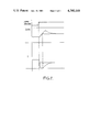
- FIG. 2 is a series of graphs illustrating the performance of the control shown in FIG. 1 and
- FIG. 3 is a diagram of a modified form of the invention.
- the system described is intended to control the fuel flow to a ducted fan type gas turbine engine 10.
- the fuel control itself is a hydromechanical system 11 as described in detail in U.K. Patent Specification No. 1465477 and will not be described in detail herein, the present invention being concerned with the generation of an electrical signal to control an electromechanical trim element 12 in the form of a torque motor providing a mechanical trim input to the system 11.
- the trim signal generating circuit utilizes an input signal dependent on the engine parameter known as the integrated exhaust pressure ratio (IEPR), which is derived by dividing an electrical signal representing the integrated exhaust pressure (IEP), being a pressure at the tapping of an air potentiometer connected between one pressure tapping downstream of the fan 13 of the engine and another pressure tapping at the outlet 14 of the core engine, by an electrical signal representing the pressure in the engine air intake upstream of the fan 13.
- IEPR integrated exhaust pressure ratio
- An IEPR demand signal generator 15 is provided to calculate the desired value of the IEPR signal for any given position of the pilots lever PLA (with other engine variables as additional inputs to this generator).
- the actual IEPR signal and the IEPR demand signal are applied to an error signal generator 16, the error signal output of which is applied to the inputs of an integrator 17 and a linear amplifier 18, the outputs of which are added together to generate the trim signal which is applied to the trim element 12.
- the PLA signal is also supplied along with signals from the IEPR demand signal generator 15 and from a temperature transducer 7 sensitive to the air intake temperature, to a trim datum signal generator 8.
- This generator 8 calculates a trim datum signal by dividing a signal representing the difference between a permitted maximum high pressure spool speed at the existing PLA setting and a permitted minimum speed at that setting by a calculated desired speed signal derived by multiplying a function of IEPR demand by a function of the temperature signal.
- trim datum signal is not used during normal steady state running of the engine, since the closed loop, incorporating the error generator 16, the integrator 17 and the proportional amplifier 18 normally maintains the error signal at zero. Following a rapid change in PLA, however, there will be a step change in the IEPR demand signal and the effect of integrator 17 will be to cause the trim element 12 to be driven to one or other of its extremes whilst engine acceleration (or deceleration) is being controlled by other means (not shown in the drawing). This will result in a large overshoot at the end of acceleration or deceleration.
- the error signal is connected via an absolute value circuit 19 to a reference comparator 20 connected to operate an integrator setting circuit 21 which causes the integrator output to take up a level such that the sum of its output and that of the amplifier 18 is equal to the trim datum signal whenever the magnitude of error signal exceeds the reference level.
- a reference comparator 20 connected to operate an integrator setting circuit 21 which causes the integrator output to take up a level such that the sum of its output and that of the amplifier 18 is equal to the trim datum signal whenever the magnitude of error signal exceeds the reference level.
- the upper graph shows a step change in the IEPR demand and the solid lines in the middle and lower graphs show how the actual IEPR and the current supplied to the trim element 12 vary with time following the step change.
- the dotted lines show the performance without the reset circuit 21 operating.
- a differentiator 30 is interposed between the error signal generator 16 and the absolute value circuit 19.
- the effect of this modification is to cause the integrator 17 output to be set as previously described when the absolute value of the rate of change of the error signal exceeds a set threshold, rather than when the absolute value of the error signal exceeds that threshold.
- the result of this is that there is no danger of a steady state latch-up condition occurring. In the original circuit latch-up could occur if the effect of imposing the trim was to cause the error to remain above the threshold.
- the integrator 17 is externally set only during transient conditions and once the error has stabilised the normal integral and proportional trim loop is re-established.
- the other change as compared with the original circuit is provision of a closed loop determining the value of the constant K.
- This loop includes an integrator 31 connected to integrate the difference between the output of the summing junction between the integrator 17 and ampifier 18 and the output of a multiplier 32.
- the output of integrator 31 is supplied to a function generator 33 the characteristic of which is as shown in the diagram--i.e. its output its constant and positive when the integrator output is low, constant and larger when the integrator output is high, and linearly varying between these two constant values for intermediate values of the integrator output.
- the multiplier 32 has one input from the trim datum generator 8 and another from the function generator 33 and its output is applied to the integrator setting circuit 21.
- This closed loop operates so that in steady conditions the output of multiplier 32 is equal to the output of the integrator 17 (the output of amplifier 16 being zero in these conditions).
- the output of the trim datum generator occurs more quickly than changes in the output of integrator 31, so that the multiplier K value set during the previous steady state condition is used to multiply the new trim datum signal.
- the two constant levels of the output of the function generator 33 determine limits to the value of K which are respectively lower and higher than the normal range of values which K will adopt during steady state conditions, but the value of the output of the integrator 31 during large change transient conditions will cause these limits to be reached. In these conditions there is no point in attempting to maintain the value of K "correct” because until steady state is again reached the necessary value of K cannot be accurately predicted.
Landscapes
- Engineering & Computer Science (AREA)
- Chemical & Material Sciences (AREA)
- Combustion & Propulsion (AREA)
- Physics & Mathematics (AREA)
- General Physics & Mathematics (AREA)
- Automation & Control Theory (AREA)
- Mechanical Engineering (AREA)
- General Engineering & Computer Science (AREA)
- Electrical Control Of Air Or Fuel Supplied To Internal-Combustion Engine (AREA)
- Feedback Control In General (AREA)
Applications Claiming Priority (2)
| Application Number | Priority Date | Filing Date | Title |
|---|---|---|---|
| GB7932878 | 1979-09-21 | ||
| GB7932878 | 1979-09-21 |
Publications (1)
| Publication Number | Publication Date |
|---|---|
| US4380148A true US4380148A (en) | 1983-04-19 |
Family
ID=10508000
Family Applications (1)
| Application Number | Title | Priority Date | Filing Date |
|---|---|---|---|
| US06/188,727 Expired - Lifetime US4380148A (en) | 1979-09-21 | 1980-09-19 | Device for adjusting gas turbine engine fuel control system in accordance with engine parameter |
Country Status (4)
| Country | Link |
|---|---|
| US (1) | US4380148A (enExample) |
| JP (1) | JPS5652526A (enExample) |
| CA (1) | CA1149909A (enExample) |
| FR (1) | FR2465880A1 (enExample) |
Cited By (9)
| Publication number | Priority date | Publication date | Assignee | Title |
|---|---|---|---|---|
| US4594852A (en) * | 1984-10-30 | 1986-06-17 | General Electric Company | Aircraft engine control |
| US4845943A (en) * | 1988-04-29 | 1989-07-11 | United Technologies Corporation | Control method for topping loop |
| US4884397A (en) * | 1988-04-29 | 1989-12-05 | United Technologies Corporation | Control system topping loop |
| US5231823A (en) * | 1991-08-22 | 1993-08-03 | General Electric Company | Supervisory control system |
| US5305599A (en) * | 1991-04-10 | 1994-04-26 | General Electric Company | Pressure-ratio control of gas turbine engine |
| US6389816B1 (en) | 2000-07-25 | 2002-05-21 | Honeywell International, Inc. | Simplified fuel system for jet engines |
| EP1178196A3 (en) * | 2000-07-31 | 2005-08-17 | General Electric Company | Methods and apparatus for trimming engine control systems |
| DE102007061288A1 (de) * | 2007-12-19 | 2009-06-25 | Felber, Winfried | Vorrichtung zum Verbinden von zwei Leitungen |
| US20110202251A1 (en) * | 2010-02-16 | 2011-08-18 | Telectro-Mek, Inc. | Apparatus and method for reducing aircraft fuel consumption |
Families Citing this family (1)
| Publication number | Priority date | Publication date | Assignee | Title |
|---|---|---|---|---|
| US4407118A (en) * | 1980-07-10 | 1983-10-04 | Lucas Industries Limited | Gas turbine engine fuel control system |
Citations (7)
| Publication number | Priority date | Publication date | Assignee | Title |
|---|---|---|---|---|
| US3129326A (en) * | 1961-11-21 | 1964-04-14 | Systems Inc Comp | Reset operational amplifier |
| US3231728A (en) * | 1960-07-18 | 1966-01-25 | Systems Inc Comp | Reset integrator |
| US3672163A (en) * | 1970-01-02 | 1972-06-27 | Chandler Evans Inc | Integral fuel control |
| US3790765A (en) * | 1973-02-01 | 1974-02-05 | Chandler Evans Inc | Governor with integrator reset |
| US3839860A (en) * | 1972-07-21 | 1974-10-08 | United Aircraft Corp | Automatic engine pressure ratio equalization system |
| US4159625A (en) * | 1977-02-01 | 1979-07-03 | United Technologies Corporation | Control for gas turbine engine |
| US4313167A (en) * | 1979-07-27 | 1982-01-26 | General Electric Company | Thrust control system for a gas turbine engine |
Family Cites Families (6)
| Publication number | Priority date | Publication date | Assignee | Title |
|---|---|---|---|---|
| GB1306067A (enExample) * | 1969-02-24 | 1973-02-07 | ||
| US3832846A (en) * | 1972-04-27 | 1974-09-03 | Woodward Governor Co | Speed governor with fuel rate control |
| JPS5534292B2 (enExample) * | 1974-06-13 | 1980-09-05 | ||
| GB1520882A (en) * | 1974-07-24 | 1978-08-09 | Lucas Industries Ltd | Electronic fuel control for a gas turbine engine |
| GB1573095A (en) * | 1976-11-26 | 1980-08-13 | Lucas Industries Ltd | Fuel control for a multi engine gas turbine installation |
| DE2702774C3 (de) * | 1977-01-24 | 1980-12-18 | Bodenseewerk Geraetetechnik Gmbh, 7770 Ueberlingen | Vorrichtung zur Drehzahlregelung von Turbo-Luftstrahltriebwerken |
-
1980
- 1980-09-18 CA CA000360465A patent/CA1149909A/en not_active Expired
- 1980-09-19 US US06/188,727 patent/US4380148A/en not_active Expired - Lifetime
- 1980-09-19 FR FR8020225A patent/FR2465880A1/fr active Granted
- 1980-09-22 JP JP13085680A patent/JPS5652526A/ja active Pending
Patent Citations (7)
| Publication number | Priority date | Publication date | Assignee | Title |
|---|---|---|---|---|
| US3231728A (en) * | 1960-07-18 | 1966-01-25 | Systems Inc Comp | Reset integrator |
| US3129326A (en) * | 1961-11-21 | 1964-04-14 | Systems Inc Comp | Reset operational amplifier |
| US3672163A (en) * | 1970-01-02 | 1972-06-27 | Chandler Evans Inc | Integral fuel control |
| US3839860A (en) * | 1972-07-21 | 1974-10-08 | United Aircraft Corp | Automatic engine pressure ratio equalization system |
| US3790765A (en) * | 1973-02-01 | 1974-02-05 | Chandler Evans Inc | Governor with integrator reset |
| US4159625A (en) * | 1977-02-01 | 1979-07-03 | United Technologies Corporation | Control for gas turbine engine |
| US4313167A (en) * | 1979-07-27 | 1982-01-26 | General Electric Company | Thrust control system for a gas turbine engine |
Cited By (11)
| Publication number | Priority date | Publication date | Assignee | Title |
|---|---|---|---|---|
| US4594852A (en) * | 1984-10-30 | 1986-06-17 | General Electric Company | Aircraft engine control |
| US4845943A (en) * | 1988-04-29 | 1989-07-11 | United Technologies Corporation | Control method for topping loop |
| US4884397A (en) * | 1988-04-29 | 1989-12-05 | United Technologies Corporation | Control system topping loop |
| US5305599A (en) * | 1991-04-10 | 1994-04-26 | General Electric Company | Pressure-ratio control of gas turbine engine |
| US5231823A (en) * | 1991-08-22 | 1993-08-03 | General Electric Company | Supervisory control system |
| US5305595A (en) * | 1991-08-22 | 1994-04-26 | General Electric Company | Supervisory control method |
| US6389816B1 (en) | 2000-07-25 | 2002-05-21 | Honeywell International, Inc. | Simplified fuel system for jet engines |
| EP1178196A3 (en) * | 2000-07-31 | 2005-08-17 | General Electric Company | Methods and apparatus for trimming engine control systems |
| DE102007061288A1 (de) * | 2007-12-19 | 2009-06-25 | Felber, Winfried | Vorrichtung zum Verbinden von zwei Leitungen |
| US20110202251A1 (en) * | 2010-02-16 | 2011-08-18 | Telectro-Mek, Inc. | Apparatus and method for reducing aircraft fuel consumption |
| US8290683B2 (en) | 2010-02-16 | 2012-10-16 | Telectro-Mek, Inc. | Apparatus and method for reducing aircraft fuel consumption |
Also Published As
| Publication number | Publication date |
|---|---|
| FR2465880A1 (fr) | 1981-03-27 |
| CA1149909A (en) | 1983-07-12 |
| JPS5652526A (en) | 1981-05-11 |
| FR2465880B1 (enExample) | 1983-03-11 |
Similar Documents
| Publication | Publication Date | Title |
|---|---|---|
| US5083277A (en) | Fuel control system | |
| US4995232A (en) | Running control for a gas turbine engine | |
| US5023793A (en) | Apparatus and method for dynamic compensation of a propeller pitch speed control governor | |
| JP3039947B2 (ja) | ガスタービンの燃料制御装置 | |
| US4018044A (en) | Electronic fuel control for a gas turbine engine | |
| US4437303A (en) | Fuel control system for a gas turbine engine | |
| US3421317A (en) | Electrical control systems for engines | |
| EP0185600B1 (en) | A transient derivative scheduling control system | |
| CA1172730A (en) | Fuel control system for gas turbine engine | |
| US4100731A (en) | Fuel control for a multi-engine gas turbine installation | |
| US4380148A (en) | Device for adjusting gas turbine engine fuel control system in accordance with engine parameter | |
| JPH0416618B2 (enExample) | ||
| US4206597A (en) | Fan R.P.M. control loop stabilization using high rotor speed | |
| US4644744A (en) | Control device for controlling an engine of a turbine power system having more than one engine | |
| JPS646481B2 (enExample) | ||
| KR0121787B1 (ko) | 공회전 및 감속 중의 내연 기관의 공기비를 조절하는 방법 및 그 장치 | |
| KR0151710B1 (ko) | 차량용 내연기관의 작동 매개 변수의 제어 시스템 | |
| US3928962A (en) | Fuel control systems for gas turbine engines | |
| KR910004767B1 (ko) | 내연기관의 회전수 제어장치 | |
| US3357177A (en) | Gas turbine engine fuel control system | |
| US3820321A (en) | Acceleration control for gas turbine engine | |
| US3938321A (en) | Gas turbine control | |
| CN113167179A (zh) | 具有故障管理的控制飞行器涡轮发动机转速的系统和方法 | |
| US3381470A (en) | Fuel control system for a gas turbine engine | |
| GB2059631A (en) | Gas turbine engine fuel control system |
Legal Events
| Date | Code | Title | Description |
|---|---|---|---|
| STCF | Information on status: patent grant |
Free format text: PATENTED CASE |