US437726A - Pipe-welding apparatus - Google Patents
Pipe-welding apparatus Download PDFInfo
- Publication number
- US437726A US437726A US437726DA US437726A US 437726 A US437726 A US 437726A US 437726D A US437726D A US 437726DA US 437726 A US437726 A US 437726A
- Authority
- US
- United States
- Prior art keywords
- bell
- skelp
- roller
- pipe
- tongue
- Prior art date
- Legal status (The legal status is an assumption and is not a legal conclusion. Google has not performed a legal analysis and makes no representation as to the accuracy of the status listed.)
- Expired - Lifetime
Links
Images
Classifications
-
- B—PERFORMING OPERATIONS; TRANSPORTING
- B21—MECHANICAL METAL-WORKING WITHOUT ESSENTIALLY REMOVING MATERIAL; PUNCHING METAL
- B21C—MANUFACTURE OF METAL SHEETS, WIRE, RODS, TUBES, PROFILES OR LIKE SEMI-MANUFACTURED PRODUCTS OTHERWISE THAN BY ROLLING; AUXILIARY OPERATIONS USED IN CONNECTION WITH METAL-WORKING WITHOUT ESSENTIALLY REMOVING MATERIAL
- B21C37/00—Manufacture of metal sheets, rods, wire, tubes, profiles or like semi-manufactured products, not otherwise provided for; Manufacture of tubes of special shape
- B21C37/06—Manufacture of metal sheets, rods, wire, tubes, profiles or like semi-manufactured products, not otherwise provided for; Manufacture of tubes of special shape of tubes or metal hoses; Combined procedures for making tubes, e.g. for making multi-wall tubes
- B21C37/08—Making tubes with welded or soldered seams
Definitions
- My present invention relates to an improvement in pipe-welding bells, and it has resemblance in some respects to the improvement for which, on January 28, 1890, I obtained United States Letters Patent No. 420,213.
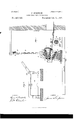
- Figure 1 is a vertical 1 longitudinal section of my improved pipewelding apparatus.
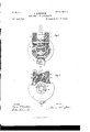
- Fig: 2 is a front elevation of the skelp-supporting roller at the back of the bell.
- Fig. 3 is a vertical cross-section of the bell on the line III III of Fig. 1. a rear elevation of the bell, partly in section, on the line IV IV of Fig. 1.
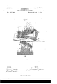
- Fig. 5 is a vertical central section of a modified construction of the bell.
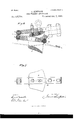
- Fig. 6 is a vertical central section, and
- Fig. 7 is a plan view of a modified construction.
- Figs. 1 and 3, 2 represents the pipe-welding bell, which is approximately of the form of the bells now commonly employed for making butt-welded pipe.
- the front portion of the tongue 3 is constructed as shown in Fig. 4;, being formed in a circular arc in cross-section and set concentrically in the bell, so as to leave an intermediate space I), which is approximately equal to the thickness of the skelp-iron.
- the circular portion of the tongue does not, how ever, extend around its entire circumference, but at its under part it is cut, as at c, to form a space for the passage of the tag in the operation of drawin the skelp through the bell.
- a roller 6 journaled on a pin '7, extending through the roller and through the tongue.
- the periphery of the roller is curved laterally to conform to the curvature of the tongue 3, and projects slightly above the surface of the tongue, so as to form a support for the skelp on the inner side of the seam during the welding of the pipe.
- the roller is journaled in said recess preferably as follows: Straps 9, having curved ends, are set on seats 10 on the bell at the sides of the strap of the bracket 4, and their curved ends project into the recess on the top of the bell, forming brackets between which the roller 8 is journaled. These straps 9 are held to the bell by bolts 11. I
- the roller 8 may be otherwise journaled; but the device which I have described for this purpose is convenient, since if the roller becomes worn the straps may be removed and a new roller substituted without difficulty, or if the bell should become worn out the straps and roller may be removed for use on another bell.
- roller 12 on the side of the bell opposite to the roller 8.
- This roller is set in a recess formed in the bell, so that its periphery shall project but slightly to the interior of the bell, and it is journaled between lugs formed at the ends of a strap 13, which is held to the bell by bolts 14.
- the purpose of this roller is to enable the skelp to be drawn through the bell without the great friction and wear on the bottom of the bell which ordinarily takes place.
- this bell In the use of this bell it is placed in a bellholder 15, which is set in the usual bracket 16 in front of the furnace-door, as shown in Fig. 1, and the bell may be upheld by a chain gles to the natural course of the pipe and this wear is prevented.
- the tag After heating the skelp, the tag is passed through the hole 0 and the skelp is drawn through the bell, the action of which turns up the skelp around the tongue 3 and welds the edges together to form the pipe.
- the seam ofthe pipe is directly between the rollers 6 and 8.
- the roller 6 supports the seam, and, together with the roller 8, presses upon it, so as to make the weld very thorough.
- edges of the skelp are preferably somewhat scarfed, so as to en hance the benefit of this action of the rollers.
- the rollers 6, 8, and 12 also reduce the friction of drawing the pipe through the bell and enable it to be drawn with less effort and better results than have heretofore been possible.
- FIG. 5 I show amodified form of the apparatus, in which, instead of employing a single roller 6 at the end of the tongue 3, I employ two such rollers 6 l3, and directly opposite thereto, so as to bear on the exterior of theskelp, I journal two other rollers 8 8, the advanced roller 8 being journaled in a prolongation of the straps 9, which thus constitutes a tongue which bears on the skelpseam in advance of the bell after the skelp has emerged from the bell.
- This is of advantage, because it gives to the skelp-seam a supplementary compressing and welding, and thereby makes a better and stronger pipe.
- the tongue 3 and the strap 9 (which also serves as a tongue) at their advanced bearing on the skelp are preferably provided with rollers, for the purpose of reducing the friction of drawing the pipe; but it should be understood that this is not indispensable, since these points of bearing may be without rollers.
- Figs. 6 and 7 I show the strap 9 and tongue 3 projecting beyond the end of the bell and having at their ends rollers 6 8, which bear on the pipe-seam, while in the bell no rollers are shown.
- the strap 9 and the bracket of the tongue 3 may also be made of separate pieces bolted together, as shown in these figures.
- I may employ a roller 20 interposed between the bell and the furnace and journaled in bearings 21, provided with abar 22 overlying the roller, pivoted at 23, and provided with a hand-lever 24.
- the roller has at its middle portion a peripheral groove 25 to permit passage of the tag.
- Thebar 22 may consist of a roller journaled on its longitudinal axis.
Landscapes
- Engineering & Computer Science (AREA)
- Mechanical Engineering (AREA)
Description
(N0 Model 4 Sheets-Sheet 1. J. SIMPSQN. PIPE WELDING APPARATUS.
No. 437,726. Patented Oct. 7, 1890.
INVENTOR.
WITNESSES (No Model.) 4 Sheets Sheet 2.
J. SIMPSON. PIPE WELDING APPARATUS.
No. 437,726. Patented Oct. '7, 1890.
(No Model.) 4 Sheets-Sheet 3.
J. SIMPSON. PIPE WELDING APPARATUS.
No. 437,726. Patented .Oct. 7, 1890.
i J a a WITNESSES INVENTOR.
(No Model.) 4 Sheets-Sheet 4.
J. SIMPSON. PIPE WELDING APPARATUS.
No. 437,726. Patented Oct. 7, 1890.
WITNESSES ZZZWM rrnn STATES PATENT, OFFICE.
JAMES SIMPSON, OF MCKEESPORT, PENNSYLVANIA.
Pl PE-WELDI NG APPARATUS.
SPECIFICATION forming part of Letters Patent No. 437,726, dated October '7, 1890.
Original application filed May 8, 1890, Serial No. 851,021. Divided and this application filed September 8, 1890. Serial No. 364,219.
(No model.) 7
To all whom it may concern.-
Be it known that 1, JAMES SIMPSON, of Mo- Keesport,in the county of Alleghenyand State of Pennsylvania, have invented a new and usef ul Improvement in Pipe-IVelclin g Apparatus, of which the following is a full, clear, and exact description.
My present invention relates to an improvement in pipe-welding bells, and it has resemblance in some respects to the improvement for which, on January 28, 1890, I obtained United States Letters Patent No. 420,213.
It consists, first, ina pipe-welding bell provided with internal rollers, the function of which is to serve as anti-friction means to save wear on the bell and to facilitate the drawing of the skelp therethrough. In the drawings I show such rollers placed only at diametricallyopposite points in the bell, though it should be understood that as many rollers or sets of rollers may be set around the internal periphery of the bell as may be desirable.
It consists, secondly, in the combination, with the bell, of a roller which bears on the exterior of the skelp at the seam, and a tongue or roller situate oppositely thereto at the interior of the skelp, so that the interposed seam shall be pressed by these parts.
It consists, thirdly, in the use of a tongue having its external outline substantially circular in cross-section and arranged concentrically within the bell, so as to support and sustain a considerable internal area of the skelp, a cavity being afforded at the side of the tongue to permit passage of the tag.
It consists, fourthly, in the combination, with the bell, of a tongue or roller which bears on the seam at the exterior of the skelp at a point in advance of the bell, and an opposite internal tongue or roller which bears on the seam at the interior of the skelp, so that the seam shall be pressed between these parts after the skelp has emerged from the bell.
It consists, fifthly, in the combination, with the bell,of means situate in the rear th ereof,for holding and centering the skelp and preventing it from twisting in the bell, and to insure the seam being maintained in a single direct line.
It consists, sixthly, in certain preferred de tails of construction, hereinafter particularly indicated.
In the accompanying drawings, forming part of this specification, Figure 1 is a vertical 1 longitudinal section of my improved pipewelding apparatus. Fig: 2 is a front elevation of the skelp-supporting roller at the back of the bell. Fig. 3 is a vertical cross-section of the bell on the line III III of Fig. 1. a rear elevation of the bell, partly in section, on the line IV IV of Fig. 1. Fig. 5 is a vertical central section of a modified construction of the bell. Fig. 6 is a vertical central section, and Fig. 7 is a plan view of a modified construction.
Like symbols of reference indicate like parts in each.
In the drawings, Figs. 1 and 3, 2 represents the pipe-welding bell, which is approximately of the form of the bells now commonly employed for making butt-welded pipe.
3 is a tongue or mandrel which extends into the interior of the bell from the rear or larger end thereof, and which may be provided with an upwardly-extending bracket 4, having a bent portion which fits on the top of the bell and is secured thereto by bolts 5, in the manner described in my prior patent, No. 420,213. The front portion of the tongue 3 is constructed as shown in Fig. 4;, being formed in a circular arc in cross-section and set concentrically in the bell, so as to leave an intermediate space I), which is approximately equal to the thickness of the skelp-iron. The circular portion of the tongue does not, how ever, extend around its entire circumference, but at its under part it is cut, as at c, to form a space for the passage of the tag in the operation of drawin the skelp through the bell.
On the upper side of thetongue 3 is arecess in which is set a roller 6, journaled on a pin '7, extending through the roller and through the tongue. The periphery of the roller is curved laterally to conform to the curvature of the tongue 3, and projects slightly above the surface of the tongue, so as to form a support for the skelp on the inner side of the seam during the welding of the pipe. There is also a recess formed in the bell directly opposite to the position of the roller 6, and in this re Fig. 4 is cess there is journaled a roller 8, whose periphery is laterally concave to conform to the curvature of the interior of the bell, and projects slightly into the same. The roller is journaled in said recess preferably as follows: Straps 9, having curved ends, are set on seats 10 on the bell at the sides of the strap of the bracket 4, and their curved ends project into the recess on the top of the bell, forming brackets between which the roller 8 is journaled. These straps 9 are held to the bell by bolts 11. I
The roller 8 may be otherwise journaled; but the device which I have described for this purpose is convenient, since if the roller becomes worn the straps may be removed and a new roller substituted without difficulty, or if the bell should become worn out the straps and roller may be removed for use on another bell.
I prefer also to use another roller 12 on the side of the bell opposite to the roller 8. This roller is set in a recess formed in the bell, so that its periphery shall project but slightly to the interior of the bell, and it is journaled between lugs formed at the ends of a strap 13, which is held to the bell by bolts 14. The purpose of this roller is to enable the skelp to be drawn through the bell without the great friction and wear on the bottom of the bell which ordinarily takes place.
In the use of this bell it is placed in a bellholder 15, which is set in the usual bracket 16 in front of the furnace-door, as shown in Fig. 1, and the bell may be upheld by a chain gles to the natural course of the pipe and this wear is prevented. After heating the skelp, the tag is passed through the hole 0 and the skelp is drawn through the bell, the action of which turns up the skelp around the tongue 3 and welds the edges together to form the pipe. The seam ofthe pipe is directly between the rollers 6 and 8. The roller 6 supports the seam, and, together with the roller 8, presses upon it, so as to make the weld very thorough. The edges of the skelp are preferably somewhat scarfed, so as to en hance the benefit of this action of the rollers. The rollers 6, 8, and 12 also reduce the friction of drawing the pipe through the bell and enable it to be drawn with less effort and better results than have heretofore been possible.
The use of this form of bell enables me not only to make butt-welded pipe, in which the weld is formed by the meeting of squared edges of the skelp, but also to lap-weld the pipe. This I effect by a special internal construction of the bell, which is described and claimed in an application, Serial No. 351,021, filed May 8, 1890, of which this application is a division.
In Fig. 5 I show amodified form of the apparatus, in which, instead of employing a single roller 6 at the end of the tongue 3, I employ two such rollers 6 l3, and directly opposite thereto, so as to bear on the exterior of theskelp, I journal two other rollers 8 8, the advanced roller 8 being journaled in a prolongation of the straps 9, which thus constitutes a tongue which bears on the skelpseam in advance of the bell after the skelp has emerged from the bell. This is of advantage, because it gives to the skelp-seam a supplementary compressing and welding, and thereby makes a better and stronger pipe.
The tongue 3 and the strap 9 (which also serves as a tongue) at their advanced bearing on the skelp are preferably provided with rollers, for the purpose of reducing the friction of drawing the pipe; but it should be understood that this is not indispensable, since these points of bearing may be without rollers. In Figs. 6 and 7 I show the strap 9 and tongue 3 projecting beyond the end of the bell and having at their ends rollers 6 8, which bear on the pipe-seam, while in the bell no rollers are shown. I also prefer, in using the advanced bearing on the skelp in the manner shown in Figs. 6 and 7, not to bolt the strap 9 rigidly to the bell, but to afford to it a slight vertical play, as shown in Fig. 6, so that the ends of the strap and tongue may be able to yield so as to adjust themselves to the natural upward curvature of the pipe as it leaves the bell. The strap 9 and the bracket of the tongue 3 may also be made of separate pieces bolted together, as shown in these figures.
In all the forms of my improvement which I have illustrated in the drawings I show the tongue 3 provided with an anti-friction roller 26, journaled at its heel and adapted to bear on the middle of the skelp at its entrance into the bell, to prevent buckling of the skelp at that place. This is a desirable addition to my invention; but my claims are not limited to its use. I' also prefer in each case to make the tongue 3 and straps 9, or both, of spring metal, or to apply special springs thereto, so that they shall exert a sufficient pressure on the seam of the skelp.
In order to center the skelp properly in the bell and to prevent its twisting in its passage therethrough, I may employ a roller 20 interposed between the bell and the furnace and journaled in bearings 21, provided with abar 22 overlying the roller, pivoted at 23, and provided with a hand-lever 24. The roller has at its middle portion a peripheral groove 25 to permit passage of the tag. In inserting the skelp into the bell, the bar 22 being raised the tag is placed in the groove 25 and passed through the bell, and the bar 22 is then lowered into the position shown in Fig. 2.
ICC
This insures the accurate adjustment of the tag in the bell, and throughout the drawing of the skelp the bar 22 prevents the skelp from twisting and maintains the seam in a single straight line at the middle of the rollers 6 and 8, while the roller 20 serves as antifriction means to support and facilitate the passage of the skelp. Its action in this regard is shown clearly in Fig. 1.
The advantages of my invention will be appreciated by those skilled in the art.
Vithout limiting myself strictly to the precise arrangement and construction of the parts herein described and shown, I claim- 1. The combination, with a pipe-welding bell, of a roller journaled to the bell on the outside of the skelp and having its periphery substantially flush with the inner surface of the bell, substantially as and for the purposes described.
2. The combination, with a pipe-Welding bell, of a roller journaled in a recess formed in the shell of the bell 911 the outer side of the skelp, and a strap or straps extending into the recess and forming the bearings for the roller, substantially as and for the purposes described.
The combination, with a pipe-welding bell, of a roller having its periphery at the exterior of the skelp, and an interior tongue adapted to bear on the interior of the skelp opposite to the exterior roller, substantially as and for the purposes described.
4. The combination, With a pipe-Welding bell, of a tongue havinga bearing 011 the seam at the exterior of the skelp in advance of the bell, and a second tongue having an opposite bearing on the seam at the interior of the skelp, substantially as and for the purposes described.
5. The combination, with a pipe-Welding bell, of a tongue arranged Within the bell opposite to the position of the seam therein, said tongue having a periphery circular in crosssection to afford an intermediate space I) for the skelp, and formed with a longitudinal space a for passage of the tag, substantially as and for the purposes described.
6. The combination, with a pipe-Welding bell, of a bar situated back of the bell directly above the path of the skelp, and a support for the skelp beneath said bar, substantially as and for the purposes described.
7. The combination, with a pipe-welding bell, of a supporting-roller situated back of the bell directly beneath the path of the skelp, and a retaining-bar 22, situated above said supporting-roller and adj acently thereto, substantially as and for the purposes described.
8. The combination, with a pipe-Welding bell, of a skelp-supporting roller situate back of the bell and having a grooved periphery, substantially as and for the purposes described.
9. In pipe -welding apparatus, the combination, With the furnace, of a bell and bellholder, said bell-holder being backwardly inclined, substantially as and for the purposes described.
In testimony whereof I have hereunto set myhand this 5th day of September, A. D. 1890.
JAMES SIMPSON.
Witnesses:
W. B. CoRWIN, THOMAS W. BAKEWELL.
Publications (1)
| Publication Number | Publication Date |
|---|---|
| US437726A true US437726A (en) | 1890-10-07 |
Family
ID=2506626
Family Applications (1)
| Application Number | Title | Priority Date | Filing Date |
|---|---|---|---|
| US437726D Expired - Lifetime US437726A (en) | Pipe-welding apparatus |
Country Status (1)
| Country | Link |
|---|---|
| US (1) | US437726A (en) |
-
0
- US US437726D patent/US437726A/en not_active Expired - Lifetime
Similar Documents
| Publication | Publication Date | Title |
|---|---|---|
| US437726A (en) | Pipe-welding apparatus | |
| US755436A (en) | Art of manufacturing tubes. | |
| US56152A (en) | Improved machine for making metal tubes | |
| US437725A (en) | Pipe-welding apparatus | |
| US1209948A (en) | Bar for bolt-blanks. | |
| US433591A (en) | Welding seams of pipes | |
| US1056326A (en) | Manufacture of seamless tubes. | |
| US438025A (en) | Jean pierke serve | |
| US653900A (en) | Method of forming welded rings. | |
| US119235A (en) | Improvement in spindles for clothes-wringer rolls | |
| US315626A (en) | Machine for bending tube-skelp | |
| US311250A (en) | Demelitts | |
| US128911A (en) | Improvement in machines for making sheet-metal tubes | |
| US575225A (en) | Machine for making tubing | |
| US670498A (en) | Machine for upsetting edges of metal plates. | |
| US376681A (en) | Isteateix | |
| US635433A (en) | Bending-machine. | |
| US653913A (en) | Apparatus for forming pipe-couplings or similar articles. | |
| US1034954A (en) | Tube-forming machine. | |
| US1046106A (en) | Sheath-applying means. | |
| US829990A (en) | Pipe-forming apparatus. | |
| US401146A (en) | John it | |
| US1209949A (en) | Blank for flexible bolts. | |
| US572583A (en) | Peter swanger | |
| US653869A (en) | Rolls for welding coupling-blanks. |