US4373902A - Immediate ignition smokeless burning of waste gases - Google Patents
Immediate ignition smokeless burning of waste gases Download PDFInfo
- Publication number
- US4373902A US4373902A US06/228,139 US22813981A US4373902A US 4373902 A US4373902 A US 4373902A US 22813981 A US22813981 A US 22813981A US 4373902 A US4373902 A US 4373902A
- Authority
- US
- United States
- Prior art keywords
- steam
- air
- flow
- wall
- air pipe
- Prior art date
- Legal status (The legal status is an assumption and is not a legal conclusion. Google has not performed a legal analysis and makes no representation as to the accuracy of the status listed.)
- Expired - Fee Related
Links
- 239000002912 waste gas Substances 0.000 title claims abstract description 12
- 239000007789 gas Substances 0.000 claims abstract description 37
- 238000002485 combustion reaction Methods 0.000 claims description 24
- 238000010276 construction Methods 0.000 claims description 7
- 229910000831 Steel Inorganic materials 0.000 claims 2
- 239000010959 steel Substances 0.000 claims 2
- 239000000203 mixture Substances 0.000 abstract description 12
- 229910000746 Structural steel Inorganic materials 0.000 abstract description 3
- 230000000630 rising effect Effects 0.000 description 3
- 238000000926 separation method Methods 0.000 description 2
- 238000013459 approach Methods 0.000 description 1
- 238000006243 chemical reaction Methods 0.000 description 1
- 230000000694 effects Effects 0.000 description 1
- 238000002347 injection Methods 0.000 description 1
- 239000007924 injection Substances 0.000 description 1
Images


Classifications
-
- F—MECHANICAL ENGINEERING; LIGHTING; HEATING; WEAPONS; BLASTING
- F23—COMBUSTION APPARATUS; COMBUSTION PROCESSES
- F23L—SUPPLYING AIR OR NON-COMBUSTIBLE LIQUIDS OR GASES TO COMBUSTION APPARATUS IN GENERAL ; VALVES OR DAMPERS SPECIALLY ADAPTED FOR CONTROLLING AIR SUPPLY OR DRAUGHT IN COMBUSTION APPARATUS; INDUCING DRAUGHT IN COMBUSTION APPARATUS; TOPS FOR CHIMNEYS OR VENTILATING SHAFTS; TERMINALS FOR FLUES
- F23L7/00—Supplying non-combustible liquids or gases, other than air, to the fire, e.g. oxygen, steam
- F23L7/002—Supplying water
- F23L7/005—Evaporated water; Steam
-
- F—MECHANICAL ENGINEERING; LIGHTING; HEATING; WEAPONS; BLASTING
- F23—COMBUSTION APPARATUS; COMBUSTION PROCESSES
- F23G—CREMATION FURNACES; CONSUMING WASTE PRODUCTS BY COMBUSTION
- F23G7/00—Incinerators or other apparatus for consuming industrial waste, e.g. chemicals
- F23G7/06—Incinerators or other apparatus for consuming industrial waste, e.g. chemicals of waste gases or noxious gases, e.g. exhaust gases
- F23G7/08—Incinerators or other apparatus for consuming industrial waste, e.g. chemicals of waste gases or noxious gases, e.g. exhaust gases using flares, e.g. in stacks
- F23G7/085—Incinerators or other apparatus for consuming industrial waste, e.g. chemicals of waste gases or noxious gases, e.g. exhaust gases using flares, e.g. in stacks in stacks
-
- G—PHYSICS
- G01—MEASURING; TESTING
- G01B—MEASURING LENGTH, THICKNESS OR SIMILAR LINEAR DIMENSIONS; MEASURING ANGLES; MEASURING AREAS; MEASURING IRREGULARITIES OF SURFACES OR CONTOURS
- G01B11/00—Measuring arrangements characterised by the use of optical techniques
- G01B11/24—Measuring arrangements characterised by the use of optical techniques for measuring contours or curvatures
- G01B11/25—Measuring arrangements characterised by the use of optical techniques for measuring contours or curvatures by projecting a pattern, e.g. one or more lines, moiré fringes on the object
- G01B11/2518—Projection by scanning of the object
Definitions
- This invention lies in the field of the flaring of waste gases. More particularly it concerns a type of flare in which the gases are burned smokelessly.
- a still further object of this invention is to provide means to conduct secondary air from the outer periphery of the flare radially inwardly to the central core above the gas-air pipe.
- baffle or cover plate At the top of the steam-air pipe there is a baffle or cover plate, supported by a plurality of circumferentially spaced brackets, strips or legs, which are of selected width, so that they not only support the cover plate but also divide the outward radial flow of steam-air into a plurality of separated flows. Because of the deflection of the steam-air flow due to the cover plate, the flow is substantially radially into the rising annular column of flared gases to thoroughly and turbulently mix, for smokeless and complete combustion.
- the top of the outer wall of the flare is slightly higher than the top of the steam-air pipe, so that there is mixture of steam-air and gas before the flow reaches the top of the outer wall where there are a plurality of igniters of conventional design, such as shown in U.S. Pat. Nos. 2,779,399 and 2,869,632.
- Additional centralizing support is provided between the central steam-air pipe and the outer wall, by means of a plurality of radial spokes or bars, which not only serve the purpose of support, but are wide enough in construction, so that they divide the flow of gas into a plurality of separate annular segments.
- the space above these radial bars provides a low pressure area in and above them induced by the upward flow of flared gases. This low pressure creates an ignition ⁇ bridge ⁇ by drawing flame from the igniter-induced burning gases into the are where the combustible mixture of flared gases and air-stream emerge where immediate endothermal smokeless reaction burning takes place.
- FIG. 1 is a vertical diametral cross-section of the apparatus of this invention taken across the plane 1--1 of FIG. 5.
- FIG. 2A is a plan view of the steam-air pipe taken across the plane 2--2 of FIG. 2B.
- FIG. 2B is a diametral section of the top portion of the steam-air pipe, taken along the plane 2B--2B of FIG. 2A.
- FIG. 3 is an enlarged view of the steam-air supply portion of FIG. 1.
- FIG. 4 is an enlarged view of the aspirator and steam-air combination and mixing portion of FIG. 3.
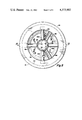
- FIG. 5 is a plan view of the entire flare taken across the plane 5--5 of FIG. 1.
- FIGS. 6, 7 and 8 show various portions of the radial steam-air tubes, and the radial bars, which provide for separation of the annular gas flow into a plurality of circumferentially spaced separate segments of the annular gas flow, respectively.
- FIG. 1 there is shown a vertical diametral cross-section of the improved waste gas flare.
- the portion 10 shown is limited to the top, or combustion control portion, which is fitted to the top of the riser pipe of a conventional flare stack by means of a flange 22.
- No need is felt for description of the lower portion of the flare stack, since this can be conventional in all respects, except that the diameter of the flare stack and the diameter of the lower portion 16 of the combustion control portion of the flare, would be of the same diameter.
- Arrows 24 illustrate the upward flow of waste gas from the riser pipe (not shown) into the bottom of the combustion portion 10. This flow of waste gas would normally be supplied to the bottom of the flare stacks in a conventional manner and rising as a circular cylindrical flow indicated by arrows 24.
- the combustion section which is of selected length, comprises a central pipe 28 of selected diameter and length, and an outer coaxial wall 20, which is of such diameter that the annular space 27 has substantially the same cross-section, as the lower cylindrical portion 16.
- the top of the central steam-air pipe 28 is at a selected dimension 70 below the top 54 of the outer cylindrical wall 20.
- a horizontal circular baffle plate 52 is provided for a cover over the steam-air pipe, and is supported by a plurality of circumferentially positioned brackets, legs or straps 50, which are welded to the steam-air pipe 28 and the plate 52.
- the width of the support straps 50 is of critical dimension as will be more fully explained in FIGS. 2A and 2B.
- the top end of the steam-air pipe is coaxially supported inside of the outer wall 20 by means of a plurality of circumferentially spaced radial baffle arms or bars 68.
- These can be of any selected cross-section, such as a horizontal strap or a circular pipe, or a piece of angle iron as shown, etc.
- a preferred construction involves the use of an angle iron which will be more fully described in FIGS. 6, 7 and 8.
- the radial bars not only provide support for the steam-air pipe, but because of their circumferential width which is of critical dimension they divide the annular flow of gas 26 into a separate circumferentially spaced plurality of circular segments, of the annular flow, for reasons which will be described later.
- the plurality of steam-air tubes 28A, 28B may be equal to, or different from, the number of radial bars 68. This will be further discussed in connection with FIG. 5.
- FIGS. 2A and 2B there are shown respectively a plan view of the top of the steam-air pipe, and a vertical cross-section of the top portion of the steam-air pipe.
- the circular plate 52 provides a baffle plate over the steam-air pipe, so as to force the upward flow of steam-air 38 into a substantially outward radial flow, through the space provided between the top edge 56 of the pipe, the horizontal cover plate 52, and the circumferentially spaced support straps 50.
- the width of the straps 50 be of a selected circumferential dimension, so that the flow 58 of the steam-air mixture between the straps 50 will be separated enough to provide a clear space 57 of lower pressure, permitting the riser of the vertical gas flow to pass between the flows 58 and to flow into the lower pressure area P1 which wlll be provided above the plate 52.
- the circumferential width of the straps 50 should be at least one inch or larger, depending on the dimensions of the steam-air pipe and the outer wall 20.
- FIGS. 3 and 4 in conjunction with FIG. 1 there is shown an enlarged view of the circular manifold box 14 for housing the steam-air aspirative injection means and to provide primary combustion air flow through a plurality of circumferentially spaced openings 40 in the outer wall 14B of the box 14.
- the construction provides two annular plates 14A at the top and 14C at the bottom which are welded to the outer surface of the outer wall 20.
- a circular baffle, dividing wall or curtain 44 is attached to and supported by the top plate 14A. This is of lesser dimension than the outer circumferential plate 14B, so as to provide flow of primary air 42 inwardly through the openings 40, down and through the space 45 under the bottom edge 39 of the wall 44, and into the exposed ends of the steam-air tubes 28A and 28B.
- the number and diameter of the radial steam-air tubes 28A and 28B should be such that the total cross-section for flow of steam-air in these smaller tubes is substantially equal to the cross-sectional area of the steam-air pipe 28.
- the manifold 14 is constructed as shown, as a piezometric control to maintain the pressure in space 25 (FIG. 3) substantially constant at atmospheric pressure. This makes it possible for the steam aspirator to be described to provide a constant steam-air ratio, in any condition of wind action or direction outside 14B.
- Annular boxes 32A and 32B around the outer ends of the steam air tubes 28A and 28B, etc. have an annular space 30, and serve as plena for the distribution of steam, which enters these plena by means of pipes 46, in accordance with arrow 48. Only one such pipe 46 is shown although it will be clear that each of the plena 30 will require a means for inflow of steam in a conventional manner. It would be well known in the art how to connect a source of steam at selected pressure to the plena 30.
- FIG. 4 shows an enlarged view of one of the pipes 28A, illustrating the construction of the steam plenum 30.
- This comprises an annular plate 60A, a cylindrical plate 60B and an outer annular plate 60C.
- the central opening in the annular plate 60C is of the dimension of the pipe 28A for inflow of primary combustion air 42.
- FIG. 5 there is shown a plan view taken across the plane 5--5 of FIG. 1.
- the steam-air pipe 28 is shown supported by the circular tubes 28A near the bottom, and the radial angle bars 68 near the top.
- the support straps 50 are shown in a manner similar to that of FIG. 2A so that there are a plurality of radial flows of steam-air substantially horizontal, between the straps 50. Thus, there will be a series of narrow spaces 57 between the flows 58 from the steam-air pipe 28, and the top plate 52.
- the specific dimension of the plate 52 should be of the order of magnitude of the diameter of the steam-air pipe 28, which should be at least 35% of the cross section of the outer wall 20, to provide a substantially horizontal component to the flow 58 of steam-air 38.
- FIGS. 6, 7 and 8 a vertical portion of the inner surface of the outer wall 20 is shown with the pipes 28A, 28B near the bottom end, and the radial bar 68 near the top. As shown in FIG. 8 the top edge of the bars 68 are even with the top 56 of the steam-air pipe 28, although they are at a selected dimension 70 below the top edge 54 of the outer wall 20.
- FIG. 6 is a cross-section taken across the plane 6--6 of FIG. 5, and illustrates the upward flow 26 of gas past the bars by the arrows 26A.
- the annular gas flow in the space below the bars is labeled 26.
- This lowering of pressure forms a quiet zone in which there is extremely stable burning along the radial length of 68 (FIG. 5) to maintain stable burning of flared gases above 52 and above 20 at all times. This reignition area above the bars provides for continuous combustion.
- FIG. 7 shows details similar to FIG. 6 and is taken across the plane 7--7 of FIG. 5.
- FIG. 8 illustrates the same shaped bars 68 but indicates that the top of the bars 68 is flush with the top edge 56 of the gas-air pipe.
- the pressure P2 below the bars 68 is above atmospheric, due to the velocity of the gas flow.
- the pressure P1 will be below atmospheric by about the same magnitude that P2 is above atmospheric.
- the quiescent space 57 between the flows 58 (FIG. 2B) provide for upward flow of gas through the spaces 57 and radially inwardly to the low pressure space P1 above the plate 52.
- the air manifold is provided for two purposes, to provide the piezometric properties to maintain a constant steam-air ratio, and also to attenuate the noise generated by the high pressure jets of steam.
Landscapes
- Engineering & Computer Science (AREA)
- Mechanical Engineering (AREA)
- General Engineering & Computer Science (AREA)
- Environmental & Geological Engineering (AREA)
- Chemical & Material Sciences (AREA)
- Combustion & Propulsion (AREA)
- Computer Vision & Pattern Recognition (AREA)
- Physics & Mathematics (AREA)
- General Physics & Mathematics (AREA)
- Incineration Of Waste (AREA)
Priority Applications (5)
| Application Number | Priority Date | Filing Date | Title |
|---|---|---|---|
| US06/228,139 US4373902A (en) | 1981-01-26 | 1981-01-26 | Immediate ignition smokeless burning of waste gases |
| DE8282300186T DE3263574D1 (en) | 1981-01-26 | 1982-01-14 | Immediate ignition and smokeless burning of waste gases |
| EP82300186A EP0057518B1 (de) | 1981-01-26 | 1982-01-14 | Rauchfreie Verbrennung von unmittelbar gezündeten Abgasen |
| CA000394866A CA1180995A (en) | 1981-01-26 | 1982-01-25 | Immediate ignition smokeless burning of waste gases |
| JP57010843A JPS6047486B2 (ja) | 1981-01-26 | 1982-01-26 | 廃ガス無煙燃焼装置 |
Applications Claiming Priority (1)
| Application Number | Priority Date | Filing Date | Title |
|---|---|---|---|
| US06/228,139 US4373902A (en) | 1981-01-26 | 1981-01-26 | Immediate ignition smokeless burning of waste gases |
Publications (1)
| Publication Number | Publication Date |
|---|---|
| US4373902A true US4373902A (en) | 1983-02-15 |
Family
ID=22855979
Family Applications (1)
| Application Number | Title | Priority Date | Filing Date |
|---|---|---|---|
| US06/228,139 Expired - Fee Related US4373902A (en) | 1981-01-26 | 1981-01-26 | Immediate ignition smokeless burning of waste gases |
Country Status (5)
| Country | Link |
|---|---|
| US (1) | US4373902A (de) |
| EP (1) | EP0057518B1 (de) |
| JP (1) | JPS6047486B2 (de) |
| CA (1) | CA1180995A (de) |
| DE (1) | DE3263574D1 (de) |
Cited By (6)
| Publication number | Priority date | Publication date | Assignee | Title |
|---|---|---|---|---|
| US4652233A (en) * | 1981-01-10 | 1987-03-24 | Jgc Corporation | Ground flare stack |
| US4681531A (en) * | 1983-09-23 | 1987-07-21 | Magyar Asvanyolaj Es Foldgaz Kiserleti | Process and equipment for the thermic conversion of the components of gas currents contaminating the environment |
| RU2262039C2 (ru) * | 2003-12-04 | 2005-10-10 | Корнилов Виктор Николаевич | Способ сжигания углеводородного топлива и устройство для его реализации (варианты) |
| US20100291492A1 (en) * | 2009-05-12 | 2010-11-18 | John Zink Company, Llc | Air flare apparatus and method |
| WO2014179656A3 (en) * | 2013-05-03 | 2016-04-21 | Uop Llc | Apparatus and method for minimizing smoke formation in a flaring stack |
| US10584873B1 (en) * | 2016-05-06 | 2020-03-10 | David Bacon | Flare gas assembly |
Families Citing this family (4)
| Publication number | Priority date | Publication date | Assignee | Title |
|---|---|---|---|---|
| JPS6095429U (ja) * | 1983-12-07 | 1985-06-29 | 株式会社栗本鉄工所 | 煙道用パイロツトバ−ナのアスピレ−タ |
| JPS6377495A (ja) * | 1986-09-19 | 1988-04-07 | 松下電器産業株式会社 | 洗濯機の運転方法 |
| US7967600B2 (en) | 2006-03-27 | 2011-06-28 | John Zink Company, Llc | Flare apparatus |
| CN100453906C (zh) * | 2006-11-23 | 2009-01-21 | 中国船舶重工集团公司第七一一研究所 | 蒸汽助燃型火炬燃烧器 |
Citations (14)
| Publication number | Priority date | Publication date | Assignee | Title |
|---|---|---|---|---|
| US2779399A (en) * | 1952-02-29 | 1957-01-29 | Zink Co John | Flare stack gas burner |
| US3429645A (en) * | 1967-09-20 | 1969-02-25 | Zink Co John | Flare stack burner |
| US3512911A (en) * | 1968-09-30 | 1970-05-19 | Zink Co John | Flare stack burner |
| US3539285A (en) * | 1969-03-20 | 1970-11-10 | Zink Co John | Flare stack burner assembly |
| US3628903A (en) * | 1970-05-11 | 1971-12-21 | Kenneth C Hoyt | Afterburner |
| US3697231A (en) * | 1970-12-23 | 1972-10-10 | Zink Co John | Burner assembly for flare stack |
| US3732059A (en) * | 1971-05-28 | 1973-05-08 | Zink Co John | Burner for gaseous fuels in reduced oxygen and/or significant velocity atmosphere |
| US3817695A (en) * | 1972-06-13 | 1974-06-18 | Zink Co John | Airductor flare |
| US3954385A (en) * | 1975-02-24 | 1976-05-04 | John Zink Company | Air powered smokeless flare |
| US3994671A (en) * | 1975-03-14 | 1976-11-30 | Combustion Unlimited Incorporated | Flare gas burner |
| US4052142A (en) * | 1976-05-17 | 1977-10-04 | John Zink Company | Air velocity burner |
| US4084935A (en) * | 1976-03-15 | 1978-04-18 | John Zink Company | Smoke suppressant mixer for flared gases |
| US4105394A (en) * | 1976-10-18 | 1978-08-08 | John Zink Company | Dual pressure flare |
| US4128389A (en) * | 1977-08-22 | 1978-12-05 | Combustion Unlimited Incorporated | Flare stack gas burner |
Family Cites Families (2)
| Publication number | Priority date | Publication date | Assignee | Title |
|---|---|---|---|---|
| GB1323674A (en) * | 1969-06-24 | 1973-07-18 | Ici Ltd | Flare stacks and steam/air mixing devices therefor |
| US4217088A (en) * | 1977-03-28 | 1980-08-12 | John Zink Company | Burner for very low pressure gases |
-
1981
- 1981-01-26 US US06/228,139 patent/US4373902A/en not_active Expired - Fee Related
-
1982
- 1982-01-14 DE DE8282300186T patent/DE3263574D1/de not_active Expired
- 1982-01-14 EP EP82300186A patent/EP0057518B1/de not_active Expired
- 1982-01-25 CA CA000394866A patent/CA1180995A/en not_active Expired
- 1982-01-26 JP JP57010843A patent/JPS6047486B2/ja not_active Expired
Patent Citations (14)
| Publication number | Priority date | Publication date | Assignee | Title |
|---|---|---|---|---|
| US2779399A (en) * | 1952-02-29 | 1957-01-29 | Zink Co John | Flare stack gas burner |
| US3429645A (en) * | 1967-09-20 | 1969-02-25 | Zink Co John | Flare stack burner |
| US3512911A (en) * | 1968-09-30 | 1970-05-19 | Zink Co John | Flare stack burner |
| US3539285A (en) * | 1969-03-20 | 1970-11-10 | Zink Co John | Flare stack burner assembly |
| US3628903A (en) * | 1970-05-11 | 1971-12-21 | Kenneth C Hoyt | Afterburner |
| US3697231A (en) * | 1970-12-23 | 1972-10-10 | Zink Co John | Burner assembly for flare stack |
| US3732059A (en) * | 1971-05-28 | 1973-05-08 | Zink Co John | Burner for gaseous fuels in reduced oxygen and/or significant velocity atmosphere |
| US3817695A (en) * | 1972-06-13 | 1974-06-18 | Zink Co John | Airductor flare |
| US3954385A (en) * | 1975-02-24 | 1976-05-04 | John Zink Company | Air powered smokeless flare |
| US3994671A (en) * | 1975-03-14 | 1976-11-30 | Combustion Unlimited Incorporated | Flare gas burner |
| US4084935A (en) * | 1976-03-15 | 1978-04-18 | John Zink Company | Smoke suppressant mixer for flared gases |
| US4052142A (en) * | 1976-05-17 | 1977-10-04 | John Zink Company | Air velocity burner |
| US4105394A (en) * | 1976-10-18 | 1978-08-08 | John Zink Company | Dual pressure flare |
| US4128389A (en) * | 1977-08-22 | 1978-12-05 | Combustion Unlimited Incorporated | Flare stack gas burner |
Cited By (6)
| Publication number | Priority date | Publication date | Assignee | Title |
|---|---|---|---|---|
| US4652233A (en) * | 1981-01-10 | 1987-03-24 | Jgc Corporation | Ground flare stack |
| US4681531A (en) * | 1983-09-23 | 1987-07-21 | Magyar Asvanyolaj Es Foldgaz Kiserleti | Process and equipment for the thermic conversion of the components of gas currents contaminating the environment |
| RU2262039C2 (ru) * | 2003-12-04 | 2005-10-10 | Корнилов Виктор Николаевич | Способ сжигания углеводородного топлива и устройство для его реализации (варианты) |
| US20100291492A1 (en) * | 2009-05-12 | 2010-11-18 | John Zink Company, Llc | Air flare apparatus and method |
| WO2014179656A3 (en) * | 2013-05-03 | 2016-04-21 | Uop Llc | Apparatus and method for minimizing smoke formation in a flaring stack |
| US10584873B1 (en) * | 2016-05-06 | 2020-03-10 | David Bacon | Flare gas assembly |
Also Published As
| Publication number | Publication date |
|---|---|
| EP0057518A2 (de) | 1982-08-11 |
| JPS57144811A (en) | 1982-09-07 |
| CA1180995A (en) | 1985-01-15 |
| EP0057518A3 (en) | 1983-03-16 |
| JPS6047486B2 (ja) | 1985-10-22 |
| DE3263574D1 (en) | 1985-06-27 |
| EP0057518B1 (de) | 1985-05-22 |
Similar Documents
| Publication | Publication Date | Title |
|---|---|---|
| CA1147252A (en) | Oil burner | |
| US3940234A (en) | Noiseless pms burner | |
| US4162140A (en) | NOx abatement in burning of gaseous or liquid fuels | |
| US5145359A (en) | Burner for thermic generators | |
| US4128389A (en) | Flare stack gas burner | |
| US4373902A (en) | Immediate ignition smokeless burning of waste gases | |
| JPS6130163B2 (de) | ||
| CA1120848A (en) | Apparatus for burning gases | |
| US4900244A (en) | Gas flaring method and apparatus | |
| CA1040090A (en) | Flare gas burner | |
| US4152108A (en) | Steam injection to zone of onset of combustion in fuel burner | |
| US5588380A (en) | Diffuser for coal nozzle burner | |
| US4084935A (en) | Smoke suppressant mixer for flared gases | |
| US3512911A (en) | Flare stack burner | |
| SE439363B (sv) | Brennare for kvevehaltiga brenslen | |
| US3429645A (en) | Flare stack burner | |
| CA1045022A (en) | Baffle | |
| US3817695A (en) | Airductor flare | |
| US2765621A (en) | Combustion apparatus with toroidal eddy flame stabilizer | |
| US4098566A (en) | Radially-injected steam for smokeless flaring | |
| CA1103574A (en) | Burner for very low pressure gases | |
| US3977186A (en) | Impinging air jet combustion apparatus | |
| US4043512A (en) | Coal burner | |
| US1613611A (en) | Gas burner | |
| GB1249967A (en) | Improvements in or relating to waste gas burners |
Legal Events
| Date | Code | Title | Description |
|---|---|---|---|
| MAFP | Maintenance fee payment |
Free format text: PAYMENT OF MAINTENANCE FEE, 4TH YEAR, PL 96-517 (ORIGINAL EVENT CODE: M170); ENTITY STATUS OF PATENT OWNER: LARGE ENTITY Year of fee payment: 4 |
|
| AS | Assignment |
Owner name: KOCH ENGINEERING COMPANY, INC., KANSAS Free format text: ASSIGNMENT OF ASSIGNORS INTEREST.;ASSIGNOR:JOHN ZINK COMPANY;REEL/FRAME:005249/0775 Effective date: 19891004 |
|
| FEPP | Fee payment procedure |
Free format text: MAINTENANCE FEE REMINDER MAILED (ORIGINAL EVENT CODE: REM.); ENTITY STATUS OF PATENT OWNER: LARGE ENTITY |
|
| LAPS | Lapse for failure to pay maintenance fees | ||
| STCH | Information on status: patent discontinuation |
Free format text: PATENT EXPIRED DUE TO NONPAYMENT OF MAINTENANCE FEES UNDER 37 CFR 1.362 |
|
| FP | Lapsed due to failure to pay maintenance fee |
Effective date: 19910217 |