US4362345A - Provision for rotatable bearing of a cylindrical device in a bearing housing - Google Patents
Provision for rotatable bearing of a cylindrical device in a bearing housing Download PDFInfo
- Publication number
- US4362345A US4362345A US06/186,428 US18642880A US4362345A US 4362345 A US4362345 A US 4362345A US 18642880 A US18642880 A US 18642880A US 4362345 A US4362345 A US 4362345A
- Authority
- US
- United States
- Prior art keywords
- housing
- members
- roll bodies
- bearing
- cages
- Prior art date
- Legal status (The legal status is an assumption and is not a legal conclusion. Google has not performed a legal analysis and makes no representation as to the accuracy of the status listed.)
- Expired - Lifetime
Links
- 239000000463 material Substances 0.000 claims description 3
- 239000000696 magnetic material Substances 0.000 claims description 2
- 238000010276 construction Methods 0.000 description 2
- 230000002950 deficient Effects 0.000 description 1
- 238000009826 distribution Methods 0.000 description 1
- 238000005516 engineering process Methods 0.000 description 1
- 238000005096 rolling process Methods 0.000 description 1
- 238000009827 uniform distribution Methods 0.000 description 1
Images


Classifications
-
- F—MECHANICAL ENGINEERING; LIGHTING; HEATING; WEAPONS; BLASTING
- F16—ENGINEERING ELEMENTS AND UNITS; GENERAL MEASURES FOR PRODUCING AND MAINTAINING EFFECTIVE FUNCTIONING OF MACHINES OR INSTALLATIONS; THERMAL INSULATION IN GENERAL
- F16C—SHAFTS; FLEXIBLE SHAFTS; ELEMENTS OR CRANKSHAFT MECHANISMS; ROTARY BODIES OTHER THAN GEARING ELEMENTS; BEARINGS
- F16C33/00—Parts of bearings; Special methods for making bearings or parts thereof
- F16C33/30—Parts of ball or roller bearings
- F16C33/38—Ball cages
- F16C33/3818—Ball cages formed of unconnected segments
-
- B—PERFORMING OPERATIONS; TRANSPORTING
- B41—PRINTING; LINING MACHINES; TYPEWRITERS; STAMPS
- B41F—PRINTING MACHINES OR PRESSES
- B41F15/00—Screen printers
- B41F15/08—Machines
- B41F15/0831—Machines for printing webs
- B41F15/0836—Machines for printing webs by means of cylindrical screens or screens in the form of endless belts
-
- F—MECHANICAL ENGINEERING; LIGHTING; HEATING; WEAPONS; BLASTING
- F16—ENGINEERING ELEMENTS AND UNITS; GENERAL MEASURES FOR PRODUCING AND MAINTAINING EFFECTIVE FUNCTIONING OF MACHINES OR INSTALLATIONS; THERMAL INSULATION IN GENERAL
- F16C—SHAFTS; FLEXIBLE SHAFTS; ELEMENTS OR CRANKSHAFT MECHANISMS; ROTARY BODIES OTHER THAN GEARING ELEMENTS; BEARINGS
- F16C13/00—Rolls, drums, discs, or the like; Bearings or mountings therefor
- F16C13/02—Bearings
-
- F—MECHANICAL ENGINEERING; LIGHTING; HEATING; WEAPONS; BLASTING
- F16—ENGINEERING ELEMENTS AND UNITS; GENERAL MEASURES FOR PRODUCING AND MAINTAINING EFFECTIVE FUNCTIONING OF MACHINES OR INSTALLATIONS; THERMAL INSULATION IN GENERAL
- F16C—SHAFTS; FLEXIBLE SHAFTS; ELEMENTS OR CRANKSHAFT MECHANISMS; ROTARY BODIES OTHER THAN GEARING ELEMENTS; BEARINGS
- F16C19/00—Bearings with rolling contact, for exclusively rotary movement
- F16C19/02—Bearings with rolling contact, for exclusively rotary movement with bearing balls essentially of the same size in one or more circular rows
- F16C19/14—Bearings with rolling contact, for exclusively rotary movement with bearing balls essentially of the same size in one or more circular rows for both radial and axial load
- F16C19/16—Bearings with rolling contact, for exclusively rotary movement with bearing balls essentially of the same size in one or more circular rows for both radial and axial load with a single row of balls
- F16C19/163—Bearings with rolling contact, for exclusively rotary movement with bearing balls essentially of the same size in one or more circular rows for both radial and axial load with a single row of balls with angular contact
- F16C19/166—Four-point-contact ball bearings
-
- F—MECHANICAL ENGINEERING; LIGHTING; HEATING; WEAPONS; BLASTING
- F16—ENGINEERING ELEMENTS AND UNITS; GENERAL MEASURES FOR PRODUCING AND MAINTAINING EFFECTIVE FUNCTIONING OF MACHINES OR INSTALLATIONS; THERMAL INSULATION IN GENERAL
- F16C—SHAFTS; FLEXIBLE SHAFTS; ELEMENTS OR CRANKSHAFT MECHANISMS; ROTARY BODIES OTHER THAN GEARING ELEMENTS; BEARINGS
- F16C33/00—Parts of bearings; Special methods for making bearings or parts thereof
- F16C33/30—Parts of ball or roller bearings
- F16C33/58—Raceways; Race rings
- F16C33/60—Raceways; Race rings divided or split, e.g. comprising two juxtaposed rings
-
- F—MECHANICAL ENGINEERING; LIGHTING; HEATING; WEAPONS; BLASTING
- F16—ENGINEERING ELEMENTS AND UNITS; GENERAL MEASURES FOR PRODUCING AND MAINTAINING EFFECTIVE FUNCTIONING OF MACHINES OR INSTALLATIONS; THERMAL INSULATION IN GENERAL
- F16C—SHAFTS; FLEXIBLE SHAFTS; ELEMENTS OR CRANKSHAFT MECHANISMS; ROTARY BODIES OTHER THAN GEARING ELEMENTS; BEARINGS
- F16C43/00—Assembling bearings
- F16C43/04—Assembling rolling-contact bearings
- F16C43/06—Placing rolling bodies in cages or bearings
Definitions
- the invention relates to a bearing assembly for a cylindrical device in and having a bearing housing and an antifriction bearing, which comprises an antifriction bearing cage provided with roll bodies.
- Antifriction bearings for supporting shafts or other cylindrical components in general comprise two rings or discs (races), respectively, on which roll bodies (balls or rollers) can run.
- the roll bodies are supported by a cage maintaining them at a uniform distance from each other.
- the roll bodies also can run directly on the shaft (or on a cylindrical part which corresponds to the shaft) or in the bearing housing.
- the mounting and dismounting of shafts or other cylindrical components supported by way of antifriction bearings is usually connected with a considerable effort in mounting technology, even where antifriction bearings are employed whose race rings and cages are subdividable into two halves, as is known for example with radial antifriction bearings (compare Austrian patent disclosure AT-PS No. 177 617).
- an object of the invention to allow for rapid mounting and dismounting of a cylindrical component supported by way of an antifriction bearing, without the requiring the mounting and dismounting of the antifriction bearing at the same time.
- the antifriction bearing cage surrounded by the bearing housing except for a one sides circular opening.
- the roll bodies protrude through the circular opening in order to bear against the cylindrical component to be borne.
- the bearing housing is subdivided into two part bearing housings or housing members so that one of the part housings can be swiveled against the other, the antifriction bearing cage being subdivided into individual cages loosely joined sequentially.
- the possibility of swinging out of one of the housing members allows for rapid lifting up of the shaft or the supported cylindrical component, respectively, in a radial direction.
- the bearing closed along its periphery in the case of a closed bearing housing, can be opened in any position of the supported cylindrical component independently of the position of the roll bodies of the antifriction bearing. This has become possible only by the construction in accordance with the present invention where the antifriction bearing cage is formed by individual cages loosely joined in sequence.
- the support means for the roll bodies at the open ends of the swivellable housing members are advantageously formed as mechanical support means or as switchable magnets.
- the magnets can also be distributed over the full swung out housing member, such that each individual roll body of magnetic material is coordinated with a magnet.
- the individual cages, race rings and bearing housing then comprise preferably a nonmagnetic material.
- the invention can be used where frequently and in a simple way construction element supported by an antifriction bearing has to be exchanged. This is the case for example in printing presses, where a frequent change of the printing cylinder or of the circular stencils (in stencil printing machines) is required.
- FIG. 1 is a front elevational view of a stencil station of a rotary stencil printing machine provided with a bearing assembly according to the invention
- FIG. 2 is a sectional view along section line II--II of FIG. 1;
- FIG. 3 is a detail view of the region A of FIG. 1 (i.e. a view of an antifriction bearing cage);
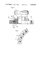
- FIGS. 4, 5 and 6 show a detailed view of the stencil housing with mechanical support means for the roll bodies in three different functional positions;
- FIG. 7 is a schematic plan view of a stencil station with opened bearing cage housing.
- the stencil station shown in FIGS. 1 and 2 for a rotary stencil printing machine comprises a circular stencil 1 supported on the front by way of the rapport wheel (or disc) 2 via an axial antifriction bearing at the machine frame 3.
- the support is provided by having the roll bodies 4 of the antifriction bearing rolling upon the race ring 2A connected to the rapport wheel 2 and upon a component rigidly connected to the machine member, the bearing housing 5 or upon the race ring 5A attached to the bearing housing.
- the bearing housing 5 is connected to the machine frame via supports 6.
- the bearing housing 5 surrounds the the antifriction bearing cage 7 such that only a one side circular opening 5B remains free through which the roll bodies 4 protrude.
- the antifriction bearing cage 7 comprises trapezoidal individual cages 7' for each roll body 4 (FIG. 3). The individual cages 7' fix the position of the roll body 4 in axial direction, that is in the direction parallel to the bearing axis.
- one of the two bearing housings is adjustable in the axial direction on the machine frame for longitudinal tensioning of the circular stencil 1.
- the bearing housing 5 is subdivided into two part housings or housing members 5', 5" by way of a plane passing through the axis, where the upper housing member 5' is provided to swing out around an axis 8 parallel to the bearing axis (see dashed line position in FIG. 1).
- the supported roll bodies 4 together with their individual cages 7' can slide out of the bearing housing 5 or the upper part housing 5', respectively, which is prevented by the magnets 9, which are switched on automatically before the bearing housing 5 is opened, in fact as soon as the circular stencil 1 releases, that is the bearing housing 5 is repositioned in the direction of the arrow 10.
- electromagnets are employable, which can be switched by a corresponding current circuit. In principle, the use of switchable permanent magnets is also possible.
- the number and distribution of the magnets 9 is provided such that upon opening of the bearing housing 5 the roll bodies occupy the desired position in the two part housings 5', 5".
- magnets 9 are only provided for the swingable upper housing member 5' of the bearing housing 5, one magnet for each roll body 4.
- the position of one of the magnets 9 deviates from a uniform distribution of the magnets 9 in order to prevent that with switched on magnets, by chance all roll bodies 4 are disposed just between two magnets 9 and are thereby subjected only to a weak magnetic field which can put the roll bodies in a labile equilibrium.
- the invention is not limited to the embodiment of an axial bearing shown or to the application in rotary stencil printing machines.
- the means according to the invention can in principle be realized with radial antifriction bearings and can be employed in other fields of application.
Landscapes
- Engineering & Computer Science (AREA)
- General Engineering & Computer Science (AREA)
- Mechanical Engineering (AREA)
- Rolling Contact Bearings (AREA)
- Rolls And Other Rotary Bodies (AREA)
Abstract
A bearing assembly for a cylindrical device, which is capable of assuring rapid exchange of the cylindrical device, comprising a bearing housing surrounding an antifriction bearing cage provided with roll bodies, wherein a circular opening remains open, through which the roll bodies protrude in order to be supported at the cylindrical device to be borne. The bearing housing is subdivided into two parts or housing members in a plane passing through the axis, so that one of the parts or housing members can be swiveled against the other. Also, the antifriction bearing cage is subdivided, namely into individual cages loosely joined together.
Description
The invention relates to a bearing assembly for a cylindrical device in and having a bearing housing and an antifriction bearing, which comprises an antifriction bearing cage provided with roll bodies.
Antifriction bearings for supporting shafts or other cylindrical components in general comprise two rings or discs (races), respectively, on which roll bodies (balls or rollers) can run. In general, the roll bodies are supported by a cage maintaining them at a uniform distance from each other. In certain cases, the roll bodies also can run directly on the shaft (or on a cylindrical part which corresponds to the shaft) or in the bearing housing. The mounting and dismounting of shafts or other cylindrical components supported by way of antifriction bearings is usually connected with a considerable effort in mounting technology, even where antifriction bearings are employed whose race rings and cages are subdividable into two halves, as is known for example with radial antifriction bearings (compare Austrian patent disclosure AT-PS No. 177 617).
It is therefore, an object of the invention to allow for rapid mounting and dismounting of a cylindrical component supported by way of an antifriction bearing, without the requiring the mounting and dismounting of the antifriction bearing at the same time.
This is achieved in accordance with the invention by having the antifriction bearing cage surrounded by the bearing housing except for a one sides circular opening. The roll bodies protrude through the circular opening in order to bear against the cylindrical component to be borne. The bearing housing is subdivided into two part bearing housings or housing members so that one of the part housings can be swiveled against the other, the antifriction bearing cage being subdivided into individual cages loosely joined sequentially.
The possibility of swinging out of one of the housing members allows for rapid lifting up of the shaft or the supported cylindrical component, respectively, in a radial direction. The bearing, closed along its periphery in the case of a closed bearing housing, can be opened in any position of the supported cylindrical component independently of the position of the roll bodies of the antifriction bearing. This has become possible only by the construction in accordance with the present invention where the antifriction bearing cage is formed by individual cages loosely joined in sequence. It is advantageous to have support means for the roll bodies or their individual cages, respectively, disposed at least in the region of the two openings of the swivellable upper part housing, which not only guarantees a reliable motion of the roll bodies of the antifriction bearing with closed bearing housing, but prevents automatically escape of the roll bodies with the individual cages from the swung out housing member. In closed position of the bearing housing the slot between the two part housings does not cause any functional disadvantages. The roll bodies pass completely unloaded over the slot, pushed by the following cage part. In contrast to the jolts felt by the wheels of railroad cars at the joints of the rails, in the antifriction bearing in accordance with the present invention the roll bodies pass over the slot between the housing members without a jolt.
The support means for the roll bodies at the open ends of the swivellable housing members are advantageously formed as mechanical support means or as switchable magnets. The magnets can also be distributed over the full swung out housing member, such that each individual roll body of magnetic material is coordinated with a magnet. The individual cages, race rings and bearing housing then comprise preferably a nonmagnetic material.
The invention can be used where frequently and in a simple way construction element supported by an antifriction bearing has to be exchanged. This is the case for example in printing presses, where a frequent change of the printing cylinder or of the circular stencils (in stencil printing machines) is required.
In the Drawing:
FIG. 1 is a front elevational view of a stencil station of a rotary stencil printing machine provided with a bearing assembly according to the invention;
FIG. 2 is a sectional view along section line II--II of FIG. 1;
FIG. 3 is a detail view of the region A of FIG. 1 (i.e. a view of an antifriction bearing cage);
FIGS. 4, 5 and 6 show a detailed view of the stencil housing with mechanical support means for the roll bodies in three different functional positions; and
FIG. 7 is a schematic plan view of a stencil station with opened bearing cage housing.
The stencil station shown in FIGS. 1 and 2 for a rotary stencil printing machine comprises a circular stencil 1 supported on the front by way of the rapport wheel (or disc) 2 via an axial antifriction bearing at the machine frame 3.
The support is provided by having the roll bodies 4 of the antifriction bearing rolling upon the race ring 2A connected to the rapport wheel 2 and upon a component rigidly connected to the machine member, the bearing housing 5 or upon the race ring 5A attached to the bearing housing. The bearing housing 5 is connected to the machine frame via supports 6. The bearing housing 5 surrounds the the antifriction bearing cage 7 such that only a one side circular opening 5B remains free through which the roll bodies 4 protrude. The antifriction bearing cage 7 comprises trapezoidal individual cages 7' for each roll body 4 (FIG. 3). The individual cages 7' fix the position of the roll body 4 in axial direction, that is in the direction parallel to the bearing axis.
As is indicated in FIG. 2 by way of the arrow 10, one of the two bearing housings is adjustable in the axial direction on the machine frame for longitudinal tensioning of the circular stencil 1.
The bearing housing 5 is subdivided into two part housings or housing members 5', 5" by way of a plane passing through the axis, where the upper housing member 5' is provided to swing out around an axis 8 parallel to the bearing axis (see dashed line position in FIG. 1). In this position the supported roll bodies 4 together with their individual cages 7' can slide out of the bearing housing 5 or the upper part housing 5', respectively, which is prevented by the magnets 9, which are switched on automatically before the bearing housing 5 is opened, in fact as soon as the circular stencil 1 releases, that is the bearing housing 5 is repositioned in the direction of the arrow 10. Preferably, electromagnets are employable, which can be switched by a corresponding current circuit. In principle, the use of switchable permanent magnets is also possible.
The number and distribution of the magnets 9 is provided such that upon opening of the bearing housing 5 the roll bodies occupy the desired position in the two part housings 5', 5". In the embodiment shown magnets 9 are only provided for the swingable upper housing member 5' of the bearing housing 5, one magnet for each roll body 4. However, the position of one of the magnets 9 deviates from a uniform distribution of the magnets 9 in order to prevent that with switched on magnets, by chance all roll bodies 4 are disposed just between two magnets 9 and are thereby subjected only to a weak magnetic field which can put the roll bodies in a labile equilibrium. By disposing nonuniformly one of the magnets 9 a force is exerted upon the roll bodies 4 while in labile equilibrium to transfer the roll bodies 4 into a stable equilibrium where each roll body 4 is disposed in a strong magnetic field region and is safely maintained in the swung out housing. Especially when the separating plane between the two housing members 5', 5" of the bearing housing 5 does not run horizontally, it is advantageous to dispose magnets also at the lower housing member magnets in order to prevent an escape of a roll body 4 together with its cage 7' from the lower housing member. In case as shown in FIG. 1 the upper housing member 5' is of the same size as the lower (the upper housing member could also be larger than the lower) then in each housing member 5', 5" the same number of roll bodies 4 is provided.
Instead of the magnets, mechanical support means can be employed for the roll bodies 4, especially those of the upper housing member 5' as can be recognized from FIGS. 4 to 6. In the two housing member 5' and 5" of the bearing housing there are provided the roll bodies 4 with the individual cages 7', which are now formed as circular discs. It can happen that a roll body 4 with individual cage 7' is just disposed in the region of the separating plane of the two housing member 5' and 5" (FIG. 4). In this case the bearing housing should not be opened. Rather, prior to opening, the spring loaded pin 11 is inserted so that in the region of the separating plane of the two housing member 5', 5" there is disposed in each case a roll body 4 with individual cage 7' on each side of the separating plane (FIG. 5). Then the screw 12 is opened and the upper part housing 5' is swung out. In this phase the cam 13 releases the wedge 14 and the spring 15 moves the push rod 16 under the disc shaped individual cage 7' (FIG. 6). At the side opposite to the opening side of the bearing housing 5, that is where the swivel axis 8 (FIG. 1) of the two part housings is disposed, the same mechanism is provided with cam 13, wedge 14, spring 15 and push rod 16. The two push ords 16 prevent a falling of the roll body together with individual cages 7' from the open upper housing member 5'.
It can be recognized from FIG. 4 that in a stencil station with a bearing described in accordance with FIGS. 1 to 3 there is performed rapidly and simply a change in stencil: Only the upper housing member 5' of the bearing housing have to be swung out; then the circular stencil 1 with the color tube 17 can be lifted out from the top.
This advantage does not entail the disadvantage of a deficient bearing of the circular stencil 1, since with a closed bearing housing 5 the circular stencil 1 is supported at its two front ends as in usual circumferentially closed antifriction bearings in bearing housings connected to the machine frame 3.
The invention is not limited to the embodiment of an axial bearing shown or to the application in rotary stencil printing machines. The means according to the invention can in principle be realized with radial antifriction bearings and can be employed in other fields of application.
Claims (8)
1. A bearing assembly for a replaceable cylindrical component, comprising:
an annular bearing housing formed by a pair of housing members and defining a separating plane, said housing being formed with a circular lateral opening;
pivot means for swingably interconnecting said members on one side of a separating plane thereof whereby at least one of said members can be swung away from the other of said members about a pivot axis defined by said pivot means to enable removal of said component from and replacement of said component in said bearing assembly;
a multiplicity of roll bodies spaced around said housing and protruding through said opening to bear upon said component;
respective bearing cages individual to said roll bodies and received in said housing members, said cages being movable with said roll bodies around said housing; and
support means for retaining said roll bodies and said cages in the respective housing members when said one of said housing members is swung away from the other of said housing members.
2. The bearing assembly defined in claim 1 wherein said housing is provided along a lateral side opposite said circular opening with a race ring, said roll bodies running along said ring.
3. The bearing assembly defined in claim 1 wherein said roll bodies consist of magnetic material, said housing consists of nonmagnetic material, said cages consist of nonmagnetic material and said support means includes magnets operable to attract said roll bodies and retain the same in said housing members.
4. The bearing assembly defined in claim 3 wherein at least one of said magnets is provided for each of said roll bodies at least on said one of said members.
5. The bearing assembly defined in claim 1 wherein said support means includes at least one pin on at least one of said members retractable from but insertable into the path of said cages for maintaining said roll bodies and said cages in the respective members upon the swinging of said one of said members away from the other of said members.
6. The bearing assembly defined in claim 1 wherein said cages are of substantially trapezoidal shape.
7. The bearing assembly defined in claim 1 wherein said cages are circular discs.
8. The bearing assembly defined in claim 1 or claim 4 wherein said component is a circular stencil of a rotary stencil printing machine having a rapport wheel and said roll bodies bear against said rapport wheel.
Applications Claiming Priority (2)
| Application Number | Priority Date | Filing Date | Title |
|---|---|---|---|
| AT0602179A AT368255B (en) | 1979-09-13 | 1979-09-13 | DEVICE FOR ROTATABLE STORAGE OF A CYLINDRICAL COMPONENT IN A BEARING HOUSING WITH THE AID OF A ROLLER BEARING |
| AT6021/79 | 1979-09-13 |
Publications (1)
| Publication Number | Publication Date |
|---|---|
| US4362345A true US4362345A (en) | 1982-12-07 |
Family
ID=3582070
Family Applications (1)
| Application Number | Title | Priority Date | Filing Date |
|---|---|---|---|
| US06/186,428 Expired - Lifetime US4362345A (en) | 1979-09-13 | 1980-09-12 | Provision for rotatable bearing of a cylindrical device in a bearing housing |
Country Status (3)
| Country | Link |
|---|---|
| US (1) | US4362345A (en) |
| AT (1) | AT368255B (en) |
| DE (1) | DE3034472A1 (en) |
Families Citing this family (2)
| Publication number | Priority date | Publication date | Assignee | Title |
|---|---|---|---|---|
| FR2586069B1 (en) * | 1985-08-06 | 1989-06-30 | Nadella | LANDLESS BEARING WITH LOCALIZED PRESSURE MOUNTED ON A SHAFT BY LATERAL ENGAGEMENT |
| DE19633670A1 (en) * | 1996-08-21 | 1998-02-26 | Voith Sulzer Finishing Gmbh | Mechanism permitting easy interchange of rollers in calender stack |
Citations (7)
| Publication number | Priority date | Publication date | Assignee | Title |
|---|---|---|---|---|
| GB332012A (en) * | 1929-06-06 | 1930-07-17 | Cooper Roller Bearings Company | Improvements relating to roller bearings |
| US2682435A (en) * | 1953-07-17 | 1954-06-29 | Walter G Rien | Split roller bearing assembly |
| US3239288A (en) * | 1963-10-24 | 1966-03-08 | Boeing Co | Self-lubricating compositions |
| US3291542A (en) * | 1964-03-06 | 1966-12-13 | Birdsboro Corp | Journal bearing |
| US3486212A (en) * | 1966-04-08 | 1969-12-30 | Textron Inc | Method of making a ball-bearing retainer |
| US3929389A (en) * | 1973-12-07 | 1975-12-30 | Voest Ag | Expansion bearing assembly for a converter carrying trunnion |
| US3989323A (en) * | 1975-05-12 | 1976-11-02 | Fmc Corporation | Composite bearing assemblies |
-
1979
- 1979-09-13 AT AT0602179A patent/AT368255B/en not_active IP Right Cessation
-
1980
- 1980-09-12 US US06/186,428 patent/US4362345A/en not_active Expired - Lifetime
- 1980-09-12 DE DE19803034472 patent/DE3034472A1/en not_active Withdrawn
Patent Citations (7)
| Publication number | Priority date | Publication date | Assignee | Title |
|---|---|---|---|---|
| GB332012A (en) * | 1929-06-06 | 1930-07-17 | Cooper Roller Bearings Company | Improvements relating to roller bearings |
| US2682435A (en) * | 1953-07-17 | 1954-06-29 | Walter G Rien | Split roller bearing assembly |
| US3239288A (en) * | 1963-10-24 | 1966-03-08 | Boeing Co | Self-lubricating compositions |
| US3291542A (en) * | 1964-03-06 | 1966-12-13 | Birdsboro Corp | Journal bearing |
| US3486212A (en) * | 1966-04-08 | 1969-12-30 | Textron Inc | Method of making a ball-bearing retainer |
| US3929389A (en) * | 1973-12-07 | 1975-12-30 | Voest Ag | Expansion bearing assembly for a converter carrying trunnion |
| US3989323A (en) * | 1975-05-12 | 1976-11-02 | Fmc Corporation | Composite bearing assemblies |
Also Published As
| Publication number | Publication date |
|---|---|
| DE3034472A1 (en) | 1981-04-02 |
| ATA602179A (en) | 1982-01-15 |
| AT368255B (en) | 1982-09-27 |
Similar Documents
| Publication | Publication Date | Title |
|---|---|---|
| US3922018A (en) | Separable bearing axle assembly and supported hub of a bicycle wheel or the like | |
| US3920290A (en) | Ball transfer unit | |
| US4371218A (en) | Bearing mechanism | |
| US4362345A (en) | Provision for rotatable bearing of a cylindrical device in a bearing housing | |
| FR2622119B1 (en) | CASTER SKATE HAVING AT LEAST TWO CASTERS MOUNTED IN A MEDIAN PLAN | |
| US2468399A (en) | Caster fixture | |
| US3669243A (en) | Conveyor roll arrangement | |
| IT8123131A0 (en) | ROLLING BEARING CAGE IN ONE OR MORE PIECES, PARTICULARLY INTENDED FOR CYLINDRICAL ROLLER BEARINGS. | |
| PT101048A (en) | MULTIDIRECTIONAL CONVEYOR | |
| ATE104445T1 (en) | GAMMA CAMERA WITH DUAL DETECTORS AND INDEPENDENT RADIAL MOVEMENTS. | |
| US5011305A (en) | Cage for a sectorial antifriction bearing | |
| US3608127A (en) | Caster wheel arrangement | |
| ATE61456T1 (en) | LEADERSHIP ROLE. | |
| EP0684408A1 (en) | Roller bearing sheave assembly | |
| DK0620061T3 (en) | Apparatus for rapid replacement and retention of a sidewall in a machine for continuous casting of a metallic product between rollers | |
| US4312546A (en) | Journal bearing for high-speed tubular shaft | |
| US3706059A (en) | Annular magnet | |
| US4008861A (en) | Web roll retainer | |
| US2683066A (en) | Unit hub and bearing assembly | |
| GB2008204A (en) | Bearings | |
| EP0264264A3 (en) | Rolling bearing with rolling retainer members | |
| ES377115A1 (en) | IMPROVEMENTS IN RAILWAY INSTALLATIONS. | |
| SU1393956A1 (en) | Sliding-contact bearing for operation in magnetic field | |
| SU1537357A1 (en) | Method and apparatus for eddy current stirring of molten core of continuously-cast ingot | |
| PL79639B1 (en) |
Legal Events
| Date | Code | Title | Description |
|---|---|---|---|
| STCF | Information on status: patent grant |
Free format text: PATENTED CASE |