US4354455A - Apparatus for oscillating a gas manifold in a rotary disc reactor - Google Patents
Apparatus for oscillating a gas manifold in a rotary disc reactor Download PDFInfo
- Publication number
- US4354455A US4354455A US06/234,858 US23485881A US4354455A US 4354455 A US4354455 A US 4354455A US 23485881 A US23485881 A US 23485881A US 4354455 A US4354455 A US 4354455A
- Authority
- US
- United States
- Prior art keywords
- gas manifold
- shaft
- sweep
- plate
- oscillation
- Prior art date
- Legal status (The legal status is an assumption and is not a legal conclusion. Google has not performed a legal analysis and makes no representation as to the accuracy of the status listed.)
- Expired - Fee Related
Links
- 230000010355 oscillation Effects 0.000 claims abstract description 26
- 230000001360 synchronised effect Effects 0.000 claims description 3
- 230000003534 oscillatory effect Effects 0.000 claims 1
- 230000002093 peripheral effect Effects 0.000 description 26
- 235000012431 wafers Nutrition 0.000 description 25
- 239000004065 semiconductor Substances 0.000 description 15
- 238000005229 chemical vapour deposition Methods 0.000 description 4
- XUIMIQQOPSSXEZ-UHFFFAOYSA-N Silicon Chemical compound [Si] XUIMIQQOPSSXEZ-UHFFFAOYSA-N 0.000 description 2
- 230000004913 activation Effects 0.000 description 2
- 230000003247 decreasing effect Effects 0.000 description 2
- 238000010586 diagram Methods 0.000 description 2
- 229910052710 silicon Inorganic materials 0.000 description 2
- 239000010703 silicon Substances 0.000 description 2
- BLRPTPMANUNPDV-UHFFFAOYSA-N Silane Chemical compound [SiH4] BLRPTPMANUNPDV-UHFFFAOYSA-N 0.000 description 1
- 238000010276 construction Methods 0.000 description 1
- 239000000463 material Substances 0.000 description 1
- 238000000034 method Methods 0.000 description 1
- 229910000077 silane Inorganic materials 0.000 description 1
- 239000000758 substrate Substances 0.000 description 1
Images
Classifications
-
- C—CHEMISTRY; METALLURGY
- C23—COATING METALLIC MATERIAL; COATING MATERIAL WITH METALLIC MATERIAL; CHEMICAL SURFACE TREATMENT; DIFFUSION TREATMENT OF METALLIC MATERIAL; COATING BY VACUUM EVAPORATION, BY SPUTTERING, BY ION IMPLANTATION OR BY CHEMICAL VAPOUR DEPOSITION, IN GENERAL; INHIBITING CORROSION OF METALLIC MATERIAL OR INCRUSTATION IN GENERAL
- C23C—COATING METALLIC MATERIAL; COATING MATERIAL WITH METALLIC MATERIAL; SURFACE TREATMENT OF METALLIC MATERIAL BY DIFFUSION INTO THE SURFACE, BY CHEMICAL CONVERSION OR SUBSTITUTION; COATING BY VACUUM EVAPORATION, BY SPUTTERING, BY ION IMPLANTATION OR BY CHEMICAL VAPOUR DEPOSITION, IN GENERAL
- C23C16/00—Chemical coating by decomposition of gaseous compounds, without leaving reaction products of surface material in the coating, i.e. chemical vapour deposition [CVD] processes
- C23C16/44—Chemical coating by decomposition of gaseous compounds, without leaving reaction products of surface material in the coating, i.e. chemical vapour deposition [CVD] processes characterised by the method of coating
- C23C16/455—Chemical coating by decomposition of gaseous compounds, without leaving reaction products of surface material in the coating, i.e. chemical vapour deposition [CVD] processes characterised by the method of coating characterised by the method used for introducing gases into reaction chamber or for modifying gas flows in reaction chamber
-
- C—CHEMISTRY; METALLURGY
- C30—CRYSTAL GROWTH
- C30B—SINGLE-CRYSTAL GROWTH; UNIDIRECTIONAL SOLIDIFICATION OF EUTECTIC MATERIAL OR UNIDIRECTIONAL DEMIXING OF EUTECTOID MATERIAL; REFINING BY ZONE-MELTING OF MATERIAL; PRODUCTION OF A HOMOGENEOUS POLYCRYSTALLINE MATERIAL WITH DEFINED STRUCTURE; SINGLE CRYSTALS OR HOMOGENEOUS POLYCRYSTALLINE MATERIAL WITH DEFINED STRUCTURE; AFTER-TREATMENT OF SINGLE CRYSTALS OR A HOMOGENEOUS POLYCRYSTALLINE MATERIAL WITH DEFINED STRUCTURE; APPARATUS THEREFOR
- C30B25/00—Single-crystal growth by chemical reaction of reactive gases, e.g. chemical vapour-deposition growth
- C30B25/02—Epitaxial-layer growth
- C30B25/14—Feed and outlet means for the gases; Modifying the flow of the reactive gases
-
- Y—GENERAL TAGGING OF NEW TECHNOLOGICAL DEVELOPMENTS; GENERAL TAGGING OF CROSS-SECTIONAL TECHNOLOGIES SPANNING OVER SEVERAL SECTIONS OF THE IPC; TECHNICAL SUBJECTS COVERED BY FORMER USPC CROSS-REFERENCE ART COLLECTIONS [XRACs] AND DIGESTS
- Y10—TECHNICAL SUBJECTS COVERED BY FORMER USPC
- Y10T—TECHNICAL SUBJECTS COVERED BY FORMER US CLASSIFICATION
- Y10T74/00—Machine element or mechanism
- Y10T74/18—Mechanical movements
- Y10T74/18056—Rotary to or from reciprocating or oscillating
- Y10T74/18184—Crank, pitman, and lever
Definitions
- This invention pertains to rotary disc reactors in which a stack of semiconductor wafers is subjected to chemical vapor deposition of material for epitaxial growth on the wafers. More particularly, this invention pertains to oscillation of a rotatable gas manifold which is used in such rotary disc reactors to sweep a stream of gas across the semiconductor wafers in order to equalize epitaxial growth across the surfaces of the semiconductor wafers.
- U.S. Pat. No. 4,062,318 to Ban et al. discloses apparatus for use in chemical vapor deposition (CVD) in a rotary disc reactor.
- CVD chemical vapor deposition
- the gas manifold and the semiconductor wafers are held fixed with respect to each other, the epitaxial layer which is grown on the wafer substrate will be non-uniform in thickness and will be thickest at the central region of the wafer.
- This patent teaches that more uniform growth of an epitaxial layer may be achieved by oscillating the gas manifold back and forth to sweep a stream of gas across the surface of each semiconductor wafer.
- This patent also teaches that it is advantageous to increase sweep speed when the stream of gas is swept across the central regions of the semiconductor wafers and to decrease sweep speed when the gas is swept across the peripheral regions of the semiconductor wafers. Since the central regions of the semiconductor wafers are always swept for less time than are the peripheral regions of the semiconductor wafers, excessive growth rates of the epitaxial layer at the central regions of the semiconductor wafers are reduced if not eliminated.
- the rotating shaft of an electric motor is connected to the gas manifold of the rotaryy disc reactor by a variable sweep means.
- the variable sweep means converts rotation of the shaft into reciprocating oscillation of the gas manifold between two extrema.
- a control means for varying electric motor speed is connected to the electric motor, to vary oscillation speed of the gas manifold within a single sweep between its two extrema.
- FIG. 1 is a schematic block diagram of an embodiment of the invention.
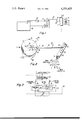
- FIG. 2 is a top view of the variable sweep means used in the embodiment of the invention.
- FIG. 3 is a block diagram of the control means for varying the speed of the electric motor shown in FIG. 1.
- a gas manifold 2 is shown rotatably mounted to rotate about a vertical axis of rotation 4 within a rotary disc reactor (not otherwise shown but of the type described in the above-mentioned Ban, et al. patent).
- Gas manifold 2 directs streams of gas, such as silane, over the surfaces of a plurality of semiconductor wafers 6, which are placed one above the other to form a vertical stack within the rotary disc reactor.
- gas manifold 2 for construction details of gas manifold 2, the rotary disc reactor, and the susceptors (not shown) which support semiconductor wafers 6, and for details of the gas distributed by gas manifold 2, reference may be made to U.S. Pat. No. 4,062,318 to Ban, et al.
- An electric motor 8 has a shaft 10 which is rotated about an axis parallel to axis of rotation 4 and is rigidly connected to the center of a circular plate 12.
- Plate 12 is shown in plan view in FIG. 2.
- Plate 12 is perpendicular to shaft 10, is 41/2 inches in diameter, and rotates clockwise (arrow 12a) as viewed in FIG. 2.
- Plate 12 has a plurality of holes 14 extending radially outwardly from shaft 10 in a straight line.
- a variable sweep means is provided to convert rotation of the shaft 10 into a reciprocating oscillation of the gas manifold 2.
- the sweep means is formed of a generally circular plate 12, a rod 15, and an elongated plate 24.
- the rod 15 has a first end pin 18 which engages any one of holes 14 on plate 12, and is shown engaged with the outermost one of holes 14.
- Rod 15 is length adjustable as by has two telescopic pieces 16 and 17. One such piece 16 is threaded into the other such piece 17 as to make the length of rod 15 adjustable for reasons set forth below.
- Rod 15 also has a second end pin 20 which can be engaged in any single one of a plurality of holes 22 located in the lever sweep arm 24.
- Lever arm 24 is suitably 6 inches long, and is secured to gas manifold 2 by a bracket 25 to cause gas manifold 2 to pivot about the axis of manifold rotation 4.
- a plurality of holes 22 in lever arm 24 extend radially outwardly from axis of rotation 4 in a straight line.
- a control means 26 for varying speed of electric motor 8 includes a silicon controlled rectifier (SCR) type speed controller 28 (see FIG. 3).
- Speed controller 28 is a conventional controller arranged to provide a d.c. voltage from a rectifier such as a silicon controller rectifier (SCR), to the d.c. motor (8) whose speed is a function of the amplitude of d.c. voltage.
- a potentiometer (32 or 30 to be described) is adjusted to provide the desired motor speed by varying the voltage output from the rectifier.
- a suitable speed controller for practicing the invention is manufactured by B & B Motors and Control Corporation N.Y., N.Y., as Model No. SCR 05. In the commercially available version of this controller, one potentiometer is provided.
- the Model SCR 05 device is modified for the purposes of this invention to have two control potentiometers 30 and 32 as shown in FIG. 3.
- the potentiometers 30 and 32 are suitably 100 K ⁇ , 10 turn, Burns-
- Control means 26 further includes a time delay relay 34 which is commercially available under the designation of TDI-A-80 S from the High-G Co. Inc., Windsor Locks, Conn.
- Time delay relay 34 includes two variable timers, to serve as a peripheral timer 36 and a central timer 38 which provide two preselected time periods of different duration in sequence for each cycle.
- Time delay relay 34 moreover includes a single pole double throw switch 38a which is normally closed as indicated in FIG. 3.
- Peripheral timer 36 is operated upon the closure of switch 40. Timer 36 merely provides a time period during which motor 8 is driven via controller 28 at the speed determined by adjustment of peripheral speed potentiometer 30. This time period together with the speed of motor 8 defines the sweep portion 6P diametrically over wafer 6.
- Potentiometer 30 is normally connected to controller 28 while switch 38a is normally closed. At the end of the predetermined time for the operation of timer 36 an electrical signal via path 37 is applied to the adjustable timer 38. Timer 38 is adjusted for the time duration desired for controlling the sweep over the central portion 6C of wafer 6.
- switch 38a Upon the starting of timer 38, switch 38a is operated from the normally closed position to the closed position on the right as shown in FIG. 3 to couple potentiometer 32 into the speed controller 28 and disconnecting potentiometer 30.
- switch 38a When timer 38 has been operated for its predetermined time period, switch 38a is released back to its normally closed position connecting potentiometer 30 back into the circuit for controlling speed controller 38 and for removing from the controller circuit 28 potentiometer 32. Potentiometer 30 in circuit changes the speed of controller 28 and thus motor 8 to the original peripheral speed. The sweep of the nozzle is then continued for the peripheral portion 6P. By this time, disc 12 has been rotated 180° so that tooth 41 is in position to operate switch 40 to start timer 36.
- time delay relay 34 functions to operate motor 8 at two predetermined time periods.
- the system as illustrated in FIG. 3 is self-synchronizing so that it will within a half of the rotation of disc 12 automatically synchronize itself into two peripheral speeds portion and central speed portion of operation, as will be further explained hereinafter.
- Microswitch 40 is opened and closed by two diametrically opposed teeth 41 and 42 which are located on the periphery of plate 12 and extend radially outwardly therefrom.
- Plate 12 is oriented such that teeth 41 and 42 are in a position to correspond respectively to the two extrema positions of rotation of the manifold 2.
- Each of teeth 41 and 42 closes microswitch 40 when gas manifold 2 is rotated to a corresponding extremum in its oscillation, i.e. reaches its leftmost or rightmost position as viewed in FIG. 2.
- an oscillation amplitude of 60° for gas manifold 2 in a CVD process for, for example 21/4 inch semiconductor wafers 6.
- Such an oscillation amplitude can be achieved by placing first end pin 18 in one of holes 14, placing second end pin 20 into one of holes 22, and adjusting the length of connecting link 15 as needed. If the oscillation amplitude of gas manifold 2 is to be other than 60 degrees, such a change variation can be accomplished by suitably repositioning the first and second end pins 18 and 20 and readjusting the length of rod 15.
- variable sweep means shown in FIG. 2 is adjusted to provide a 60° oscillation of gas manifold 2.
- potentiometers 30 and 32 are adjusted to provide the desired oscillation speeds for gas manifold 2, at peripheral region 6P and central region 6C of the wafer 6, respectively.
- the sweep means is adjusted so that at its starting point, gas manifold 2 will be at an extremum in its oscillation and microswitch 40 will be closed by one of teeth 41 and 42. (In FIG. 2, microswitch 40 is shown to be closed by tooth 42.)
- time delay relay 34 to be started by starting peripheral timer 36, which in turn will allow speed controller 28 to control the speed of electric motor 8 in accordance with the preselected resistance value of potentiometer 30.
- Peripheral timer 36 is adjusted to operate for that period of time which corresponds to 45° of rotation of plate 12.
- time delay relay 34 After plate 12 has rotated 45°, e.g. through a distance such as position A to position B, time delay relay 34 will inactivate peripheral timer 36 and will activate central timer 38. Activation of central timer 38 will cause speed controller 28 to control the speed of motor 8 in accordance with the preselected resistance of potentiometer 32. Central timer 38 is then adjusted to be operated for 90° of rotation of plate 12, e.g. through a distance such as position B to position D. After such rotation has taken place, time delay relay 34 will automatically deactivate central timer 38 and will reactivate peripheral timer 36.
- Oscillation speed of gas manifold 2 when a stream of gas is directed over each central region 6C is controlled by the setting of potentiometer 32, while oscillation speed of gas manifold 2 adjacent each peripheral region 6P is controlled by the setting of potentiometer 30.
- oscillation speed can be increased and decreased within a single sweep of gas manifold 2 between its two extrema in order to make epitaxial growth upon semiconductor wafer 6 uniform.
- the point of crossover between faster and slower oscillation speeds of gas manifold 2 i.e. the boundary between peripheral region 6P and central region 6C of each semiconductor wafer 6) can be adjusted by readjusting the settings of peripheral timer 36 and central timer 38.
- the respective oscillation speeds are automatically synchronized within one half of a rotation of disc 12, that is, the distance between each of the diametrically opposed teeth 41 and 42.
- speed controller is energized by a suitable on-off control switch (not shown) which causes the motor to rotate in either of two preselected directions of rotation.
- motor 8 drives plate 12 in a clockwise direction as seen in FIG. 2.
- Switch 38a in the normally closed position places potentiometer 30 in the circuit to drive motor 8 at the predetermined peripheral speed determined by the value of the potentiometer 30.
- the manifold 2 will be swept over the surface of wafer 6 until either one of teeth 41 or 42 is in position to operate switch 40. As shown in FIG. 2, the extreme position of sweep will be adjusted so that tooth 42 corresponds to the left extremum and tooth 41 is on the right extremum of the sweep.
- timer 36 will then be energized to a time period corresponding to the peripheral portion 6P'.
- the distance for the radial portion 6P' is determined by the speed of motor 8 as well as the time of operation of timer 36.
- Timer 36 at the end of the period for peripheral portions 6P' will then energize timer 38 to thereby operate switch 34a to connect potentiometer 32 into the control circuit 28.
- Control 28 then operates motor 8 at the predetermined speed for the central portion according to the value of potentiometer 32.
- the operation then continues as described hereinabove to drive the manifold 2 across the central portion 6C until the peripheral portion 6P" is to be swept at the speed determined by the potentiometer 30 placed in the circuit by the switch 38a being returned to its normally closed position.
- the apparatus of the invention provides a means for oscillating a gas manifold in a rotary disc reactor in two independent and symmetrical sweep rates.
- the sweep can be arranged to be faster through the center portion of the wafer 6 (see 6C) than in the peripheral portion (6P') then decreasing to the original sweep rate in the opposite peripheral portion (6P") at the opposite edge of the wafer before starting the cycle again.
- Various sized wafers and different sweep rates can be provided with the apparatus of the invention.
- any one or more adjustments can be made in the length of rod 15, in the position of pin 18 or in the position of pin 20.
- the speed of the sweep at the peripheral portion is changed by adjustment of the potentiometer 30 and at the central portion by potentiometer 32.
- the dwell time at the central portion and the peripheral portion is predetermined by adjustment of the central timer 38 and the peripheral timer 36, respectively.
Landscapes
- Chemical & Material Sciences (AREA)
- General Chemical & Material Sciences (AREA)
- Chemical Kinetics & Catalysis (AREA)
- Engineering & Computer Science (AREA)
- Materials Engineering (AREA)
- Metallurgy (AREA)
- Organic Chemistry (AREA)
- Mechanical Engineering (AREA)
- Crystallography & Structural Chemistry (AREA)
Abstract
Description
Claims (13)
Priority Applications (1)
| Application Number | Priority Date | Filing Date | Title |
|---|---|---|---|
| US06/234,858 US4354455A (en) | 1981-02-17 | 1981-02-17 | Apparatus for oscillating a gas manifold in a rotary disc reactor |
Applications Claiming Priority (1)
| Application Number | Priority Date | Filing Date | Title |
|---|---|---|---|
| US06/234,858 US4354455A (en) | 1981-02-17 | 1981-02-17 | Apparatus for oscillating a gas manifold in a rotary disc reactor |
Publications (1)
| Publication Number | Publication Date |
|---|---|
| US4354455A true US4354455A (en) | 1982-10-19 |
Family
ID=22883117
Family Applications (1)
| Application Number | Title | Priority Date | Filing Date |
|---|---|---|---|
| US06/234,858 Expired - Fee Related US4354455A (en) | 1981-02-17 | 1981-02-17 | Apparatus for oscillating a gas manifold in a rotary disc reactor |
Country Status (1)
| Country | Link |
|---|---|
| US (1) | US4354455A (en) |
Cited By (3)
| Publication number | Priority date | Publication date | Assignee | Title |
|---|---|---|---|---|
| US4649859A (en) * | 1985-02-19 | 1987-03-17 | The United States Of America As Represented By The United States Department Of Energy | Reactor design for uniform chemical vapor deposition-grown films without substrate rotation |
| US5566577A (en) * | 1992-06-13 | 1996-10-22 | Itt Automotive Europe Gmbh | Driving mechanism of a windscreen wiper for an automotive vehicle |
| WO2014009606A1 (en) * | 2012-07-09 | 2014-01-16 | Beneq Oy | Apparatus and method for processing substrate |
Citations (5)
| Publication number | Priority date | Publication date | Assignee | Title |
|---|---|---|---|---|
| US1831535A (en) * | 1929-07-25 | 1931-11-10 | Triplex Safety Glass Company O | Apparatus for spraying glass, etc. |
| US2984177A (en) * | 1956-12-18 | 1961-05-16 | Ibm | Selective printer |
| US3274860A (en) * | 1964-03-23 | 1966-09-27 | Vilbiss Co | Controllable reciprocator |
| US4062318A (en) * | 1976-11-19 | 1977-12-13 | Rca Corporation | Apparatus for chemical vapor deposition |
| DE2728244A1 (en) * | 1977-06-23 | 1979-01-11 | Spezialmaschinen Pelizaeus | Automatic spray appliance for small objects - incorporates carriage with carrier plate turning through 90 degrees for second spraying |
-
1981
- 1981-02-17 US US06/234,858 patent/US4354455A/en not_active Expired - Fee Related
Patent Citations (5)
| Publication number | Priority date | Publication date | Assignee | Title |
|---|---|---|---|---|
| US1831535A (en) * | 1929-07-25 | 1931-11-10 | Triplex Safety Glass Company O | Apparatus for spraying glass, etc. |
| US2984177A (en) * | 1956-12-18 | 1961-05-16 | Ibm | Selective printer |
| US3274860A (en) * | 1964-03-23 | 1966-09-27 | Vilbiss Co | Controllable reciprocator |
| US4062318A (en) * | 1976-11-19 | 1977-12-13 | Rca Corporation | Apparatus for chemical vapor deposition |
| DE2728244A1 (en) * | 1977-06-23 | 1979-01-11 | Spezialmaschinen Pelizaeus | Automatic spray appliance for small objects - incorporates carriage with carrier plate turning through 90 degrees for second spraying |
Cited By (7)
| Publication number | Priority date | Publication date | Assignee | Title |
|---|---|---|---|---|
| US4649859A (en) * | 1985-02-19 | 1987-03-17 | The United States Of America As Represented By The United States Department Of Energy | Reactor design for uniform chemical vapor deposition-grown films without substrate rotation |
| US5566577A (en) * | 1992-06-13 | 1996-10-22 | Itt Automotive Europe Gmbh | Driving mechanism of a windscreen wiper for an automotive vehicle |
| WO2014009606A1 (en) * | 2012-07-09 | 2014-01-16 | Beneq Oy | Apparatus and method for processing substrate |
| CN104428445A (en) * | 2012-07-09 | 2015-03-18 | Beneq有限公司 | Apparatus and method for processing substrate |
| US20150167164A1 (en) * | 2012-07-09 | 2015-06-18 | Beneq Oy | Apparatus and method for processing substrate |
| CN104428445B (en) * | 2012-07-09 | 2016-04-13 | Beneq有限公司 | For the treatment of equipment and the method for substrate |
| US10023957B2 (en) * | 2012-07-09 | 2018-07-17 | Beneq Oy | Apparatus and method for processing substrate |
Similar Documents
| Publication | Publication Date | Title |
|---|---|---|
| EP0813937B1 (en) | Apparatus and method for cutting food products | |
| US4354455A (en) | Apparatus for oscillating a gas manifold in a rotary disc reactor | |
| WO1998051836A1 (en) | Apparatus, system and method for controlling emission parameters attending vaporized materials in a hv environment | |
| EP0499062A1 (en) | A temperature controlled food cooker having devices for stirring foods while cooking | |
| US4750387A (en) | System and method for grinding the saw teeth of a circular saw blade | |
| US5289090A (en) | Automatic camcorder panning device | |
| US4362953A (en) | Electronically regulated electromechanical appliance control | |
| US2621624A (en) | Apparatus for manufacture of piezo-electric elements | |
| JPH09256155A (en) | Film forming device | |
| GB2096899A (en) | Vibratory therapy apparatus | |
| JPH09224842A (en) | Automatic bread maker | |
| JPH0726379A (en) | Method for formation of thin film and device therefor | |
| US6617594B1 (en) | Method and device for ion implanting | |
| GB1566113A (en) | Providing a layer on a substrate | |
| JPS5924757B2 (en) | Program setting device for steam curing of concrete products | |
| GB8913117D0 (en) | Device for fine adjustment of the rotary cutter of a revolving radial actuating head | |
| US4363943A (en) | Interval timer | |
| JP2715502B2 (en) | Patterning machine | |
| JPH07285638A (en) | Variable type vibrator | |
| JPS5932260B2 (en) | Kamukensakuuchi | |
| JPH0429534B2 (en) | ||
| JPH09254023A (en) | Polishing device for semiconductor wafer | |
| US4936767A (en) | Rotational molding of orthodontic retainer | |
| ELLEMAN et al. | Acoustic rotation control[Patent] | |
| KR200342951Y1 (en) | Incision equipment for a grip formation of a vinyl bag |
Legal Events
| Date | Code | Title | Description |
|---|---|---|---|
| AS | Assignment |
Owner name: RCA CORPORATION, A CORP. OF DEL. Free format text: ASSIGNMENT OF ASSIGNORS INTEREST.;ASSIGNOR:LOONEY GARY W.;REEL/FRAME:003867/0774 Effective date: 19810212 |
|
| MAFP | Maintenance fee payment |
Free format text: PAYMENT OF MAINTENANCE FEE, 4TH YEAR, PL 96-517 (ORIGINAL EVENT CODE: M170); ENTITY STATUS OF PATENT OWNER: LARGE ENTITY Year of fee payment: 4 |
|
| MAFP | Maintenance fee payment |
Free format text: PAYMENT OF MAINTENANCE FEE, 8TH YEAR, PL 96-517 (ORIGINAL EVENT CODE: M171); ENTITY STATUS OF PATENT OWNER: LARGE ENTITY Year of fee payment: 8 |
|
| FEPP | Fee payment procedure |
Free format text: PAYOR NUMBER ASSIGNED (ORIGINAL EVENT CODE: ASPN); ENTITY STATUS OF PATENT OWNER: LARGE ENTITY |
|
| FEPP | Fee payment procedure |
Free format text: MAINTENANCE FEE REMINDER MAILED (ORIGINAL EVENT CODE: REM.); ENTITY STATUS OF PATENT OWNER: LARGE ENTITY |
|
| LAPS | Lapse for failure to pay maintenance fees | ||
| FP | Lapsed due to failure to pay maintenance fee |
Effective date: 19941019 |
|
| STCH | Information on status: patent discontinuation |
Free format text: PATENT EXPIRED DUE TO NONPAYMENT OF MAINTENANCE FEES UNDER 37 CFR 1.362 |