US4346549A - Agricultural machine for tedding and windrowing fodder crops - Google Patents
Agricultural machine for tedding and windrowing fodder crops Download PDFInfo
- Publication number
- US4346549A US4346549A US06/215,851 US21585180A US4346549A US 4346549 A US4346549 A US 4346549A US 21585180 A US21585180 A US 21585180A US 4346549 A US4346549 A US 4346549A
- Authority
- US
- United States
- Prior art keywords
- drum
- machine
- impelling
- tedding
- windrowing
- Prior art date
- Legal status (The legal status is an assumption and is not a legal conclusion. Google has not performed a legal analysis and makes no representation as to the accuracy of the status listed.)
- Expired - Fee Related
Links
- 230000001105 regulatory effect Effects 0.000 claims description 18
- 238000006073 displacement reaction Methods 0.000 claims description 8
- 230000009471 action Effects 0.000 claims description 7
- 230000002093 peripheral effect Effects 0.000 claims 9
- 230000001276 controlling effect Effects 0.000 claims 2
- 238000006243 chemical reaction Methods 0.000 claims 1
- 230000008878 coupling Effects 0.000 abstract description 7
- 238000010168 coupling process Methods 0.000 abstract description 7
- 238000005859 coupling reaction Methods 0.000 abstract description 7
- 230000015572 biosynthetic process Effects 0.000 description 2
- 230000000694 effects Effects 0.000 description 2
- 230000007480 spreading Effects 0.000 description 2
- 241000283690 Bos taurus Species 0.000 description 1
- 229910000831 Steel Inorganic materials 0.000 description 1
- 238000007792 addition Methods 0.000 description 1
- 230000005540 biological transmission Effects 0.000 description 1
- 230000008859 change Effects 0.000 description 1
- 238000000151 deposition Methods 0.000 description 1
- 239000000463 material Substances 0.000 description 1
- 239000002184 metal Substances 0.000 description 1
- 230000004048 modification Effects 0.000 description 1
- 238000012986 modification Methods 0.000 description 1
- 230000035515 penetration Effects 0.000 description 1
- 229920003023 plastic Polymers 0.000 description 1
- 239000004033 plastic Substances 0.000 description 1
- 238000007790 scraping Methods 0.000 description 1
- 239000010959 steel Substances 0.000 description 1
- 230000032258 transport Effects 0.000 description 1
- 230000007306 turnover Effects 0.000 description 1
Images


Classifications
-
- A—HUMAN NECESSITIES
- A01—AGRICULTURE; FORESTRY; ANIMAL HUSBANDRY; HUNTING; TRAPPING; FISHING
- A01D—HARVESTING; MOWING
- A01D84/00—Haymakers not provided for in a single one of groups A01D76/00 - A01D82/00
- A01D84/02—Haymakers not provided for in a single one of groups A01D76/00 - A01D82/00 with flexible tools
-
- A—HUMAN NECESSITIES
- A01—AGRICULTURE; FORESTRY; ANIMAL HUSBANDRY; HUNTING; TRAPPING; FISHING
- A01D—HARVESTING; MOWING
- A01D78/00—Haymakers with tines moving with respect to the machine
- A01D78/08—Haymakers with tines moving with respect to the machine with tine-carrying rotary heads or wheels
- A01D78/10—Haymakers with tines moving with respect to the machine with tine-carrying rotary heads or wheels the tines rotating about a substantially vertical axis
- A01D78/1078—Having only one row of rotors arranged on the same horizontal line perpendicular to the advance direction of the machine
Definitions
- the present invention relates to a haymaking machine comprising at least one drum which is rotatable about a substantially vertical or slightly inclined shaft and carries in its lower portion a flexible, deformable skirt for grasping and transporting the fodder.
- a machine of this type can be satisfactorily used for windrowing.
- the skirt plunges below the fodder to be displaced, whilst adapting to changes in the ground level and transports the fodder on its upper surface.
- the fodder is not dragged on the ground so that it is not soiled by the ground, which could lead to it being rejected by cattle.
- the flexible, deformable skirt is does not damage the cut fodder and young plant shoots.
- the present invention aims to provide a haymaking machine as described hereinbefore and which makes it possible to carry out both tedding and windrowing.
- a haymaking machine having at least one drum rotated about a substantially vertical or slightly inclined shaft and which in its lower part carries a flexible, deformable skirt for grasping and transporting the fodder, wherein regulatable or detachable converting means are associated with the skirt for carrying out tedding or windrowing.
- the regulatable or detachable means can be constituted by entraining or impelling means, which are movable into at least two different positions, one for tedding and the other for windrowing.
- the impelling means can be articulated to the wall of the drum(s) or to a support, preferably located within the drum(s).
- the impelling means can be oriented in the direction opposite to the drum rotation direction in such a way that they aid the displacement of the fodder on the front part of their trajectory and free it without difficulty on the lateral part of their trajectory with a view to forming a windrow.
- They can also be brought into a second position in which they have a different orientation, for example, in substantially radial planes in order to increase their engagement with the fodder.
- the latter is then entrained towards the rear of the drum(s) and is uniformly spread behind the machine, whilst being turned over.
- the support to which the impelling means are articulated can advantageously be offset with respect to the drum rotation shaft.
- This support can also be displaced and arrested in at least two different positions. In one of these positions, the impelling means to a considerable extent extend beyond the drum over the front portion of their trajectory. Thus, they aid the transportation of the fodder in said front portion and free it as soon as it reaches the rear of the drum for the purpose of forming a windrow.
- the impelling means In the other position of the offset support, the impelling means largely extend outside their drum over the rear part of their trajectory. Therefore, they again disperse behind the machine the fodder gathered up by the skirt.
- the means according to the invention can also be impelling means guided by means of rollers which when working are displaced on a cam having two guide paths or tracks.
- One of these tracks serves to guide the impelling means during windrowing, whilst the other track guides them during tedding.
- the means associated with the drum skirts for windrowing or tedding can also be constituted by one or more spreaders.
- the spreaders are positioned behind the drums and are rotated so as to spread behind the machine the fodder transported by the drum skirts.
- the spreaders can either be removed or tilted out of the fodder trajectory.
- These means can also be constituted by guide rods.
- these rods extend in the form of a mould-board above the skirts of the drums and turn over the fodder gathered up by the skirts in the manner of a plough.
- the rods are rendered inoperative, e.g. by displacing them by 180° in such a way that they extend above the drums or by removing them from the machine.
- the windrowing and tedding means are constituted by substantially V-shaped impelling means, which are joined to the drum walls. One of their sides is substantially tangential to the walls, whilst the other side is in a substantially radial plane.
- the drums are arranged in such a way that the sides of the impelling means which are substantially tangential to the drum walls come into contact with the fodder or cut herbage to be displaced. Due to their shape, these sides easily release the fodder with a view to forming a windrow.
- the drum position is reversed in such a way that it is the other sides of the impelling means which come into contact with the fodder to be displaced. As a result of their orientation, these sides interact much more vigorously with the fodder. They therefore move it towards the rear of the drums and spread it behind the machine, whilst turning over the fodder.
- an important feature consists of providing their skirts with projections, which engage between the drums during haytedding. This leads to a partial overlapping of the trajectories described by the skirts, which ensures an integral gathering up of the fodder on the ground.
- the drums are preferably moved away from one another in order to free the location of the windrow.
- the machine chassis is advantageously telescopic.
- FIG. 1 a plan view of the machine according to the invention in the tedding position.
- FIG. 2 a part sectional side view of a drum of the machine of FIG. 1.
- FIG. 3 a plan view of the machine of FIG. 1 in the windrowing position.
- FIG. 4 a part sectional side view of the drum of FIG. 3.
- FIG. 5 a section along the broken plane V--V of FIG. 4.
- FIG. 6 a part sectional plan view of a constructional variant of the drum according to the invention, with the drum in the tedding position.
- FIG. 7 a vertical section of the drum of FIG. 6.
- FIG. 8 a view identical to that of FIG. 6, with the drum in the windrowing position.
- FIG. 9 in section along the plane IX--IX of FIG. 10, another variant of the drum according to the invention in the tedding position.
- FIG. 10 a part sectional side view of the drum of FIG. 9.
- FIG. 11 a view identical to that of FIG. 9 with the drum in the windrowing position.
- FIG. 12 a part sectional plan view of another variant of the drum according to the invention in the tedding position.
- FIG. 13 a vertical section of the drum of FIG. 12.
- FIG. 14 a view identical to that of FIG. 12 with the drum in the windrowing position.
- FIG. 15 a plan view of another embodiment of the machine according to the invention in the tedding position.
- FIG. 16 a vertical section of a drum of the machine according to FIG. 15.
- FIG. 17 a plan view of the machine of FIG. 15 in the windrowing position.
- FIG. 18 in section along the plane XVIII--XVIII of FIG. 19 another variant of the drum according to the invention in the tedding position.
- FIG. 19 a section along the plane XIX--XIX of FIG. 18.
- FIG. 20 a view identical to that of FIG. 18 with the drum in the windrowing position.
- FIG. 21 a section along the plane XXI--XXI in FIG. 20.
- FIG. 22 a plan view of another embodiment of a machine according to the invention in the tedding position.
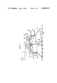
- FIG. 23 a side view of the machine of FIG. 22.
- FIG. 24 a view identical to that of FIG. 23 with the machine in the windrowing position.
- FIG. 25 a plan view of another embodiment of the machine according to the invention in the tedding position.
- FIG. 26 a side view of the machine of FIG. 25.
- FIG. 27 a view identical to that of FIG. 26 with the machine in the windrowing position.
- FIG. 28 a plan view of another embodiment of the machine according to the invention in the windrowing position.
- FIG. 29 a side view of the machine of FIG. 28.
- FIG. 30 a plan view of the machine according to FIG. 28 in the tedding position.
- the machine according to the invention comprises two drums (1, 2) interconnected by means of a chassis (3).
- the chassis is itself connected to a coupling member (4) by means of a connecting beam (5).
- the coupling member has two lower attachment points (6, 7) and an upper attachment point (8) for coupling to the three-point linkage device of a not shown tractor.
- the position of the connecting beam (5) relative to coupling member (4) can be defined by means of a cross-bar (9). Beneath each drum (1, 2) is provided a small wheel (10, 11) making it possible for the machine to travel along the ground.
- this shaft At its end located in the gear case (15), this shaft has a bevel gear which meshes with the aforementioned toothed ring, whilst at its other end extending in the gear case (16) surmounting the second drum (1), it has a second bevel gear which engages with a toothed wheel integral with drum (1).
- Each of the drums (1, 2) carries in its lower portion a flexible deformable skirt (17, 18) for grasping and transporting the fodder.
- skirts (17, 18) plunge beneath the fodder to be displaced, whilst adapting to level changes in the ground and transporting the fodder on their upper surface.
- regulatable or detachable means (19) are associated with skirts (17, 18) for carrying out windrowing or tedding.
- the means (19) are constituted by entraining or impelling means (20 to 25), which can be brought into at least two different positions, one of these positions being intended for windrowing and the other for tedding.
- the diameter (D) of the trajectories described by impelling (20, 25) differs according to whether the latter are located in one or other of the aforementioned positions.
- the diameter (D) is advantageously larger for tedding than for windrowing.
- the impelling means (20 to 25) are preferably formed by straight or curved rods, e.g. made from steel or a plastics material.
- the impelling means (20) are articulated to walls (26, 27) of drums (1, 2) by means of pins (28) positioned in a plane substantially perpendicular to the rotation shafts (12, 13) of drums (1, 2).
- Each of the impelling means (20) has two branches (29, 30) of different lengths and forming an angle ( ⁇ ) close to 90° between them.
- the branches By pivoting about the hinge pins (28) the branches can be brought into two different positions. In one of these positions, tedding can be carried out, whereas in the other position windrowing can be carried out. In the tedding position (FIGS. 1 and 2), the longest branches (29) of impelling means (20) extend in substantially radial planes.
- the branches (29) engage well on the fodder gathered up by the skirts (17, 18). They entrain it to the rear of the drums (1, 2) and spread it uniformly behind the machine, whilst turning it over.
- the shortest branches (30) of impelling means (20) are substantially tangential to the walls (16, 27), so that it has no effect on the fodder.
- the shortest branches (30) of impelling means (20) are oriented in a direction opposite to the rotation directions (F and G) of drums (1, 2), whilst branches (29) extend substantially parallel to the drum walls (26, 27).
- the branches (30) aid the displacement of the fodder on the front part of their trajectory and free it easily in the lateral part of their trajectory for the purpose of forming a windrow.
- Impelling means (20) are pivoted about the hinge pins (28) by means of positioning plate (31) arranged within the drums (1, 2). All the impelling means (20) of the same drum (1 or 2) are connected to the plate (31) by means of arms (32) passing through openings (37) provided in walls (26, 27) of drums (1, 2).
- plate (31) has a groove (33) and radial notches (34) in which engage the ends of the arms (32), which are shaped like a T.
- Plate (31) is guided on shaft (12, or 13) of drum (1 or 2) and can be vertically adjusted by means of a screw (35). The latter passes through the upper surface (36) of drums (1, 2) so that it can be manipulated from the outside.
- plate (31) When plate (31) is moved downwards, impelling means (20) are moved into the windrowing position. However, if it is moved upwards, it transfers the impelling means into the tedding position. Plate (31) also ensures the immobilisation of impelling means (20) in each of the said positions.
- impelling means (21) can pivot about spindles (39) substantially parallel to the rotation shaft (12 or 13) of the corresponding drum (1 or 2).
- the spindles (39) are arranged within the drum (1, 2) and are protected by the latter.
- the impelling means (21) extend through slots (40) made in walls (26, 27).
- Each of the spindles (39) has two impelling means (21) arranged in a superimposed manner.
- the lower impelling means is preferably oriented slightly groundwards in order to come closer to the drum skirts (17, 18).
- the impelling means are connected to a central regulating member (41) arranged within the drums (1, 2).
- This member is constituted by a hub (42) guided in rotation on the shafts (12, 13) of drums (1, 2) by ball bearings (43).
- This hub is provided with arms (44) having at their end a slot (45) in which engages a lug (46) integral with impelling means (21).
- the regulating member (41) can be correspondingly rotated about the corresponding shaft (12, 13) by means of a lever (47) positioned above the drum (1, 2).
- the lever (47) also makes it possible to immobilise the regulating member in at least two different positions by means of stop members (48, 49).
- the impelling means (22) can also pivot about spindles (50) which are substantially parallel to the shafts (12, 13) of drms (1, 2).
- Each of the impelling means (22) has an extension (51) to which is connected a tension spring (52) fixed to wall (26, 27) of drums (1, 2).
- Spindles (50) and springs (52) are positioned within drums (1, 2) and are protected by the latter.
- the impelling means (22) extend outwards through slots (53) made in walls (26, 27).
- the springs (52) exert a tension which pivots the impelling means in a direction opposite to the rotation direction (F or G) of drums (1 and 2).
- the impelling means (22) pivot towards the outside counter to the tension of springs (52) under the action of the centrifugal force resulting from the rotation speed of the drums (1, 2).
- a higher rotation speed is chosen for haytedding than for windrowing.
- the impelling means are brought into a substantially radial position so as to engage well on the fodder.
- they are oriented opposite to the rotation direction (F and G) of drums (1, 2) in order to assist the formation of a windrow (FIG. 11).
- the rotation speed change of drums (1, 2) can be brought about by means of pinions provided in the gear case (15).
- the drums (1, 2) and skirts (17, 18) can be separately driven. In this way, the latter can have the same rotation speed during tedding and windrowing.
- the impelling means (23) are articulated on a regulatable support (54) arranged within the drums (1, 2).
- the impelling means extend through ball joints (55) provided on walls (26, 27).
- the regulatable support (54) is constituted by two disks (56) connected by a tube (57) guided on a shaft (12 or 13) of drum (1 or 2) by means of ball bearings (58).
- the support (54) can be rotated about the corresponding shaft (12 or 13) by means of a lever (59).
- the latter also permits the immobilisation thereof in at least two positions defined by stop members (60, 61) on the upper face (36) of drums (1, 2).
- the support (54) makes it possible to transfer and maintain impelling means (23) in a substantially radial position which is suitable for tedding (FIG. 12) and in a position where they are oriented opposite to the rotation direction (F or G) of drum (1 or 2) (FIG. 14), suitable for windrowing.
- the impelling means (24) are articulated to a support (62) offset with respect to shaft (12, 13) of drums (1, 2).
- the drum (1,2) defines a central axis, and the shaft (12,13) extends through the interior of the drum (1,2) and is in at least one part concentric with the central axis, and in an other part thereof eccentric therewith.
- Supports (62) rotate freely on the shafts, which form an elbow (63) at the location of the supports.
- Each support (62) has two substantially symmetrical portions (64, 65) forming recesses (66) for receiving the inner end of impelling means (24).
- the lever (68) is slightly flexible and can be immmobilised on the stop member (69, 70) for locking the supports (62) in the aforementioned positions.
- the supports (62) are positioned in the rear half of the drums (1, 2) (FIG. 15).
- the impelling means (24) then project to a maximum out of the drums in the rear half of their trajectory. In this part of their trajectory, they engage well on the fodder ensuring the grasping of the fodder and its spreading behind the machine.
- the impelling means (24) are largely located within the drums (1, 2) over the front part of their trajectory.
- each support (62) is rotated by means of a spring (71) connected to the corresponding drum (1, 12).
- the impelling means (25) are articulted to walls (26, 27) by means of spindles (72) and are guided in each drum (1, 2) by levers (73) provided with rollers (74) which are displaced on a cam (75).
- This cam is mounted on shAFT (12 or 13) of corresponding drum (1 or 2) and has two guide paths or tracks (76, 77) arranged in a superimposed manner.
- Cam track (76) guides impelling means (25) during tedding (FIGS. 18 and 19) its profile is such that the impelling means extend substantially radially over most of their trajectory.
- the other track (77) of cam (75) guides the impelling means (25) during windrowing (FIGS.
- its profile is such that in the front part of their trajectory the impelling means are oriented opposite to the rotation direction (F or G) of the corresponding frum (1 or 2) and in the rear part of their trajectory, the impelling means are substantially parallel to walls (26, 27) of drums (1, 2) in order to aid the formation of a windrow.
- the rollers (74) of the levers (73) are applied to the guide tracks (76, 77) by means of springs (78), whereof one of the ends is attached to the levers and the other to lugs (79) of the walls (26, 27) of drums (1, 2).
- the transfer from the tedding position into the windrowing position and vice versa is performed by means of an adjusting screw (80) positioned in bores (81) in shafts (12, 13) of drums (1, 2). It is free in rotation, but fixed in translation.
- the threaded part (82) of the adjusting screw (80) is engaged in a lug (83) of the cam (75).
- This lug passes into bore (81) through a slot (84) provided in the corresponding shaft (12, 13).
- the cam (75) has an inclined portion (85) between the guide tracks which facilitates the passage of rollers (74) from one guide track to the other on displacing the cam.
- the means (19) associated with the skirts (17, 18) of the drums (1, 2) are two spreaders (86, 87) which can be brought into at least two different positions. They are interconnected by a beam (88), which is itself connected to the supporting shaft (3) by means of a carrying arm (89) having an articulation (90).
- the spreaders (86, 87) are constituted by hubs (91, 92) provided with substantially radial teeth (93, 94).
- the teeth (93, 94) of the two spreaders (86, 87) lightly mesh and are advantageously vertically displaced from one another in order to prevent collision thereof.
- the spreaders (86, 87) are positioned behind drums (1, 2), as shown in FIGS. 22 and 23. They are then rotated so as to turn in convergence at the front, viewed in the forward travel direction (A), by means of pinions located in the carrying arm (89) and a cross belt arranged in the connecting beam (88). In this position, the spreaders (86, 87) intercept the fodder transported rearwards by skirts (17, 18) of drums (1, 2) and again spread it behind the machine, whilst turning it over.
- the spreaders (86, 87) are tilted upwards about articulation (90) of their carrier arm (89) (FIG. 24). In the new position, they are positioned above drums (1, 2) and have no influence on the fodder gathered up by skirts (17, 18). For windrowing, the spreaders can also be dismantled from the machine to render them inoperative. Moreover, they can also be arranged horizontally without being beyond the scope of the invention.
- means (19) are constituted by rods (95) arranged at different levels and which can be brought into at least two different positions.
- These rods (95) are integral with a support (96) mounted in a U-shaped bush (97) connected to the connecting beam (5).
- This fitting in bush (97) is brought about by means of a positioning pin (98) and two bolts (99) equidistant from that pin.
- the rods (95) extend above the skirts (17, 18) substantially from a line (100) tangential to the front part of drums (1, 2) to the rear of the latter in the form of a mould-board.
- Those rods (95) which are furthest from the ground extend to the rear of the drums (1, 2) and preferably beyond planes (P) parallel to the forward travel direction (A) and passing through the rotation shafts (12, 13) of the drums.
- the fodder gathered up by the skirts (17, 18) slides along the rods (95) towards the rear of the machine. This displacement is aided by the strips (101), fixed to walls (26, 27) of drums (1, 2) and which move the fodder. As the latter slides rearwards, it is turned over by the rods (95) and drops to the ground.
- the means (19) associated with skirts (17, 18) of the drums (1, 2) are constituted by substantially V-shaped impelling means (102) which are connected to the walls (26, 27) of the drums (1, 2). They have a side (103) which is substantially tangential to the wall (26 or 27) of the drums (1 or 2) and a side (104) which is in a substantially radial plane.
- the chassis (3) connecting the two drums (1, 2) is articulated to the connecting beam (5) by means of a substantially vertical shaft, (105).
- This chassis and the two drums (1, 2) can thus pivot in a substantially horizontal plane and can be arrested in at least two positions which differ by 180° by means of a bolt (106).
- the chassis (3) has two bosses (107, 108), each having a hole in which it is possible to engage the bolt (106).
- drums (1, 2) are arranged in such a way that the sides (103) of impelling means (102) which are substantially tangential to walls (26, 27) come into contact with the fodder to be displaced. Due to their shape, the fodder easily slides along the sides (103) of impelling means (102) as soon as the latter travel towards the rear of the machine. Thus, the fodder is freed for forming a windrow. This position is shown in FIG. 28.
- drums (1, 2) are inverted through the pivoting of chassis (3).
- sides (104) of impelling means (102) come into contact with the fodder. Due to their aggressiveness, the sides entrain the fodder towards the rear of drums (1, 2) and uniformly spread it behind the machine, whilst turning it over.
- each gear case (15, 16) has a shaft end (16) for connection to the cardan shaft connected to the tractor power take-off shaft.
- the skirts (17, 18) of the drums (1, 2) are peripherally provided with projections (109), which facilitate the gathering up of the fodder.
- projections (109) of two adjacent drums (1, 2) mesh in the tedding position. This leads to a slight overlap of their trajectories ensuring that all the fodder is gathered up.
- skirts (17, 18) of two adjacent drums (1, 2) are preferably moved away from one another by a distance which is substantially the same or slightly less than the width of the windrow to be formed. This assists in the depositing of laying down of the fodder and advantageously increases the working width of the machine.
- the chassis (3) which interconnects the two drums (1, 2) is made in two parts (110, 111) which are nested into one another. The locking of these parts (110, 111) in the different positions is carried out by two set screws (112, 113).
- the shirts (17, 18) of the drums (1, 2) also have ribs (114) on their upper face. When working, these ribs aid the gathering up and displacement of the fodder.
Landscapes
- Life Sciences & Earth Sciences (AREA)
- Environmental Sciences (AREA)
- Harvesting Machines For Specific Crops (AREA)
- Harvesting Machines For Root Crops (AREA)
- Harvester Elements (AREA)
- Apparatuses For Bulk Treatment Of Fruits And Vegetables And Apparatuses For Preparing Feeds (AREA)
Applications Claiming Priority (2)
| Application Number | Priority Date | Filing Date | Title |
|---|---|---|---|
| FR7931889A FR2471734A1 (fr) | 1979-12-20 | 1979-12-20 | Machine agricole pour le fanage et l'andainage de vegetaux |
| FR7931889 | 1979-12-20 |
Publications (1)
| Publication Number | Publication Date |
|---|---|
| US4346549A true US4346549A (en) | 1982-08-31 |
Family
ID=9233239
Family Applications (1)
| Application Number | Title | Priority Date | Filing Date |
|---|---|---|---|
| US06/215,851 Expired - Fee Related US4346549A (en) | 1979-12-20 | 1980-12-12 | Agricultural machine for tedding and windrowing fodder crops |
Country Status (8)
| Country | Link |
|---|---|
| US (1) | US4346549A (ref) |
| JP (1) | JPS56102729A (ref) |
| BE (1) | BE886725A (ref) |
| DE (1) | DE3047878A1 (ref) |
| FR (1) | FR2471734A1 (ref) |
| GB (1) | GB2065436B (ref) |
| IT (1) | IT1136217B (ref) |
| NL (1) | NL8006930A (ref) |
Cited By (5)
| Publication number | Priority date | Publication date | Assignee | Title |
|---|---|---|---|---|
| US4519194A (en) * | 1982-07-08 | 1985-05-28 | Belrecolt S.A. | Hay harvesting machine |
| US4996670A (en) * | 1989-09-28 | 1991-02-26 | International Business Machines Corporation | Zero standby power, radiation hardened, memory redundancy circuit |
| US20130025251A1 (en) * | 2010-03-29 | 2013-01-31 | Forage Innovations B.V. | Device for displacing mown crop |
| USD958197S1 (en) * | 2020-08-20 | 2022-07-19 | Kuhn Sas | Tedder plate |
| USD959504S1 (en) * | 2021-02-16 | 2022-08-02 | Kuhn Sas | Tedder arm |
Families Citing this family (6)
| Publication number | Priority date | Publication date | Assignee | Title |
|---|---|---|---|---|
| FR2520578B1 (fr) * | 1982-01-29 | 1986-01-31 | Deere John Cie Francaise | Groupeur d'andains |
| CH657248A5 (de) * | 1982-03-05 | 1986-08-29 | Bucher Guyer Ag Masch | Heuwerbungsmaschine zum schwaden, wenden und zetten von geschnittenem halmgut. |
| CH661636A5 (de) * | 1983-06-08 | 1987-08-14 | Paul E Mueller Dipl Ing | Vorrichtung zum aufsammeln und bearbeiten von auf dem boden liegendem pflanzengut. |
| FR2549342B1 (fr) * | 1983-07-19 | 1987-10-02 | Kuhn Sa | Machine de fenaison perfectionnee pour le fanage |
| DE3803158A1 (de) * | 1988-02-03 | 1989-08-17 | Karl Moosbrucker | Rechenrad fuer schwader |
| DE202016007555U1 (de) * | 2016-12-12 | 2018-03-22 | Pöttinger Landtechnik Gmbh | Landwirtschaftliche Arbeitsmaschine |
Citations (3)
| Publication number | Priority date | Publication date | Assignee | Title |
|---|---|---|---|---|
| US3896613A (en) * | 1972-07-13 | 1975-07-29 | Der Lely Ary Van | Implements for the displacement of crop or like material lying on the ground |
| US4203277A (en) * | 1977-10-07 | 1980-05-20 | Samibem, S.A. | Forkless haymaking machine |
| US4269019A (en) * | 1978-06-24 | 1981-05-26 | Klockner-Humboldt-Deutz Ag | Tedding attachment for rotary harvesting mower |
Family Cites Families (9)
| Publication number | Priority date | Publication date | Assignee | Title |
|---|---|---|---|---|
| NL6702377A (ref) * | 1967-02-17 | 1968-08-19 | ||
| DE1929104C3 (de) * | 1968-08-13 | 1981-10-22 | Maschinenfabrik Fahr Ag Gottmadingen, 7702 Gottmadingen | Heuwerbungsmaschine |
| AT336331B (de) * | 1972-09-22 | 1977-04-25 | Stoll Maschf Gmbh Wilhelm | Heuwerbungsmaschine mit einer antriebswelle |
| NL7301115A (ref) * | 1973-01-25 | 1974-07-29 | ||
| AT338551B (de) * | 1973-06-12 | 1977-09-12 | Poettinger Ohg Alois | Heuwerbungsmaschine |
| NL7309381A (nl) * | 1973-07-05 | 1975-01-07 | Lely Nv C Van Der | Roteerbaar harkorgaan. |
| NL7405407A (nl) * | 1974-04-22 | 1975-10-24 | Lely Nv C Van Der | Hooibouwmachine. |
| DE2444667C2 (de) * | 1974-09-18 | 1982-10-07 | Maschinenfabrik Fahr Ag Gottmadingen, 7702 Gottmadingen | Kreiselheuwerbungsmaschine |
| FR2405007A1 (fr) * | 1977-10-07 | 1979-05-04 | Samibem Sa | Machine de fenaison sans fourches |
-
1979
- 1979-12-20 FR FR7931889A patent/FR2471734A1/fr active Granted
-
1980
- 1980-12-10 IT IT12750/80A patent/IT1136217B/it active
- 1980-12-11 GB GB8039666A patent/GB2065436B/en not_active Expired
- 1980-12-12 US US06/215,851 patent/US4346549A/en not_active Expired - Fee Related
- 1980-12-18 DE DE19803047878 patent/DE3047878A1/de not_active Withdrawn
- 1980-12-18 JP JP17813180A patent/JPS56102729A/ja active Pending
- 1980-12-18 BE BE2/58908A patent/BE886725A/fr not_active IP Right Cessation
- 1980-12-19 NL NL8006930A patent/NL8006930A/nl not_active Application Discontinuation
Patent Citations (3)
| Publication number | Priority date | Publication date | Assignee | Title |
|---|---|---|---|---|
| US3896613A (en) * | 1972-07-13 | 1975-07-29 | Der Lely Ary Van | Implements for the displacement of crop or like material lying on the ground |
| US4203277A (en) * | 1977-10-07 | 1980-05-20 | Samibem, S.A. | Forkless haymaking machine |
| US4269019A (en) * | 1978-06-24 | 1981-05-26 | Klockner-Humboldt-Deutz Ag | Tedding attachment for rotary harvesting mower |
Cited By (6)
| Publication number | Priority date | Publication date | Assignee | Title |
|---|---|---|---|---|
| US4519194A (en) * | 1982-07-08 | 1985-05-28 | Belrecolt S.A. | Hay harvesting machine |
| US4996670A (en) * | 1989-09-28 | 1991-02-26 | International Business Machines Corporation | Zero standby power, radiation hardened, memory redundancy circuit |
| US20130025251A1 (en) * | 2010-03-29 | 2013-01-31 | Forage Innovations B.V. | Device for displacing mown crop |
| US8701378B2 (en) * | 2010-03-29 | 2014-04-22 | Forage Innovations B.V. | Device for displacing mown crop |
| USD958197S1 (en) * | 2020-08-20 | 2022-07-19 | Kuhn Sas | Tedder plate |
| USD959504S1 (en) * | 2021-02-16 | 2022-08-02 | Kuhn Sas | Tedder arm |
Also Published As
| Publication number | Publication date |
|---|---|
| FR2471734A1 (fr) | 1981-06-26 |
| JPS56102729A (en) | 1981-08-17 |
| BE886725A (fr) | 1981-04-16 |
| NL8006930A (nl) | 1981-07-16 |
| GB2065436B (en) | 1983-07-06 |
| FR2471734B1 (ref) | 1985-04-26 |
| GB2065436A (en) | 1981-07-01 |
| DE3047878A1 (de) | 1981-09-17 |
| IT8012750A0 (it) | 1980-12-10 |
| IT1136217B (it) | 1986-08-27 |
Similar Documents
| Publication | Publication Date | Title |
|---|---|---|
| NL8303201A (nl) | Hooibouwmachine. | |
| US4346549A (en) | Agricultural machine for tedding and windrowing fodder crops | |
| US4202160A (en) | Crop working machine | |
| US3995416A (en) | Hay making machines | |
| US3827224A (en) | Device comprising at least one rake member adapted to rotate about an upwardly extending axis | |
| US4380142A (en) | Agricultural machine for the tedding or conditioning of fodder | |
| US4601162A (en) | Rotary mowing attachment for a tractor and the like | |
| EP0217436B1 (en) | Machine for working grass, hay or other crops on the field | |
| US4194348A (en) | Haymaking machine with rotary rake heads | |
| US3841073A (en) | Implements for the displacement of crop lying on the ground | |
| US5862659A (en) | Haymaking machine with at least one windrowing rotor | |
| US5586421A (en) | Haymaking machine | |
| US4641491A (en) | Agricultural machine | |
| US4700535A (en) | Drum-type windrowing machine | |
| EP0524668B1 (en) | A machine for processing haulm-like crops | |
| US3511040A (en) | Rotary rake | |
| DE4028349A1 (de) | Halmgutaufnahmevorrichtung | |
| US4161860A (en) | Haymaking machine | |
| US3217481A (en) | Implements for the lateral displacement of crop or like material lying on the ground | |
| US4274248A (en) | Hay harvesting machine | |
| AU741684B2 (en) | An implement for displacing crop lying on the soil | |
| NZ204657A (en) | Swathe former:gearbox drive for opposite raking directions | |
| US4062173A (en) | Hay-making machines | |
| GB2037136A (en) | Hay harvesting machine | |
| US3320734A (en) | Haymaking machines |
Legal Events
| Date | Code | Title | Description |
|---|---|---|---|
| AS | Assignment |
Owner name: BELRECOLT S.A., 67440 MARMOUTIER, FRANCE Free format text: ASSIGNMENT OF ASSIGNORS INTEREST.;ASSIGNORS:WATTRON ALBERT;QUIRIN MICHEL;REEL/FRAME:003827/0703 Effective date: 19810119 |
|
| MAFP | Maintenance fee payment |
Free format text: PAYMENT OF MAINTENANCE FEE, 4TH YEAR, PL 96-517 (ORIGINAL EVENT CODE: M170); ENTITY STATUS OF PATENT OWNER: LARGE ENTITY Year of fee payment: 4 |
|
| FEPP | Fee payment procedure |
Free format text: PAYOR NUMBER ASSIGNED (ORIGINAL EVENT CODE: ASPN); ENTITY STATUS OF PATENT OWNER: LARGE ENTITY |
|
| FEPP | Fee payment procedure |
Free format text: PAYOR NUMBER ASSIGNED (ORIGINAL EVENT CODE: ASPN); ENTITY STATUS OF PATENT OWNER: LARGE ENTITY Free format text: PAYER NUMBER DE-ASSIGNED (ORIGINAL EVENT CODE: RMPN); ENTITY STATUS OF PATENT OWNER: LARGE ENTITY |
|
| FEPP | Fee payment procedure |
Free format text: MAINTENANCE FEE REMINDER MAILED (ORIGINAL EVENT CODE: REM.); ENTITY STATUS OF PATENT OWNER: LARGE ENTITY |
|
| LAPS | Lapse for failure to pay maintenance fees | ||
| STCH | Information on status: patent discontinuation |
Free format text: PATENT EXPIRED DUE TO NONPAYMENT OF MAINTENANCE FEES UNDER 37 CFR 1.362 |
|
| FP | Lapsed due to failure to pay maintenance fee |
Effective date: 19900902 |