US4339404A - Method of controlling the film thickness at a blown film installation - Google Patents
Method of controlling the film thickness at a blown film installation Download PDFInfo
- Publication number
- US4339404A US4339404A US06/214,733 US21473380A US4339404A US 4339404 A US4339404 A US 4339404A US 21473380 A US21473380 A US 21473380A US 4339404 A US4339404 A US 4339404A
- Authority
- US
- United States
- Prior art keywords
- film
- sectors
- thickness
- cooling
- mean
- Prior art date
- Legal status (The legal status is an assumption and is not a legal conclusion. Google has not performed a legal analysis and makes no representation as to the accuracy of the status listed.)
- Expired - Lifetime
Links
Images

Classifications
-
- B—PERFORMING OPERATIONS; TRANSPORTING
- B29—WORKING OF PLASTICS; WORKING OF SUBSTANCES IN A PLASTIC STATE IN GENERAL
- B29C—SHAPING OR JOINING OF PLASTICS; SHAPING OF MATERIAL IN A PLASTIC STATE, NOT OTHERWISE PROVIDED FOR; AFTER-TREATMENT OF THE SHAPED PRODUCTS, e.g. REPAIRING
- B29C48/00—Extrusion moulding, i.e. expressing the moulding material through a die or nozzle which imparts the desired form; Apparatus therefor
- B29C48/25—Component parts, details or accessories; Auxiliary operations
- B29C48/92—Measuring, controlling or regulating
-
- B—PERFORMING OPERATIONS; TRANSPORTING
- B29—WORKING OF PLASTICS; WORKING OF SUBSTANCES IN A PLASTIC STATE IN GENERAL
- B29C—SHAPING OR JOINING OF PLASTICS; SHAPING OF MATERIAL IN A PLASTIC STATE, NOT OTHERWISE PROVIDED FOR; AFTER-TREATMENT OF THE SHAPED PRODUCTS, e.g. REPAIRING
- B29C2948/00—Indexing scheme relating to extrusion moulding
- B29C2948/92—Measuring, controlling or regulating
- B29C2948/92009—Measured parameter
- B29C2948/92114—Dimensions
- B29C2948/92152—Thickness
-
- B—PERFORMING OPERATIONS; TRANSPORTING
- B29—WORKING OF PLASTICS; WORKING OF SUBSTANCES IN A PLASTIC STATE IN GENERAL
- B29C—SHAPING OR JOINING OF PLASTICS; SHAPING OF MATERIAL IN A PLASTIC STATE, NOT OTHERWISE PROVIDED FOR; AFTER-TREATMENT OF THE SHAPED PRODUCTS, e.g. REPAIRING
- B29C2948/00—Indexing scheme relating to extrusion moulding
- B29C2948/92—Measuring, controlling or regulating
- B29C2948/92323—Location or phase of measurement
- B29C2948/92428—Calibration, after-treatment, or cooling zone
-
- B—PERFORMING OPERATIONS; TRANSPORTING
- B29—WORKING OF PLASTICS; WORKING OF SUBSTANCES IN A PLASTIC STATE IN GENERAL
- B29C—SHAPING OR JOINING OF PLASTICS; SHAPING OF MATERIAL IN A PLASTIC STATE, NOT OTHERWISE PROVIDED FOR; AFTER-TREATMENT OF THE SHAPED PRODUCTS, e.g. REPAIRING
- B29C2948/00—Indexing scheme relating to extrusion moulding
- B29C2948/92—Measuring, controlling or regulating
- B29C2948/92504—Controlled parameter
- B29C2948/92609—Dimensions
- B29C2948/92647—Thickness
-
- B—PERFORMING OPERATIONS; TRANSPORTING
- B29—WORKING OF PLASTICS; WORKING OF SUBSTANCES IN A PLASTIC STATE IN GENERAL
- B29C—SHAPING OR JOINING OF PLASTICS; SHAPING OF MATERIAL IN A PLASTIC STATE, NOT OTHERWISE PROVIDED FOR; AFTER-TREATMENT OF THE SHAPED PRODUCTS, e.g. REPAIRING
- B29C2948/00—Indexing scheme relating to extrusion moulding
- B29C2948/92—Measuring, controlling or regulating
- B29C2948/92504—Controlled parameter
- B29C2948/92704—Temperature
-
- B—PERFORMING OPERATIONS; TRANSPORTING
- B29—WORKING OF PLASTICS; WORKING OF SUBSTANCES IN A PLASTIC STATE IN GENERAL
- B29C—SHAPING OR JOINING OF PLASTICS; SHAPING OF MATERIAL IN A PLASTIC STATE, NOT OTHERWISE PROVIDED FOR; AFTER-TREATMENT OF THE SHAPED PRODUCTS, e.g. REPAIRING
- B29C2948/00—Indexing scheme relating to extrusion moulding
- B29C2948/92—Measuring, controlling or regulating
- B29C2948/92819—Location or phase of control
- B29C2948/92857—Extrusion unit
- B29C2948/92904—Die; Nozzle zone
-
- B—PERFORMING OPERATIONS; TRANSPORTING
- B29—WORKING OF PLASTICS; WORKING OF SUBSTANCES IN A PLASTIC STATE IN GENERAL
- B29C—SHAPING OR JOINING OF PLASTICS; SHAPING OF MATERIAL IN A PLASTIC STATE, NOT OTHERWISE PROVIDED FOR; AFTER-TREATMENT OF THE SHAPED PRODUCTS, e.g. REPAIRING
- B29C48/00—Extrusion moulding, i.e. expressing the moulding material through a die or nozzle which imparts the desired form; Apparatus therefor
- B29C48/03—Extrusion moulding, i.e. expressing the moulding material through a die or nozzle which imparts the desired form; Apparatus therefor characterised by the shape of the extruded material at extrusion
- B29C48/09—Articles with cross-sections having partially or fully enclosed cavities, e.g. pipes or channels
- B29C48/10—Articles with cross-sections having partially or fully enclosed cavities, e.g. pipes or channels flexible, e.g. blown foils
Landscapes
- Engineering & Computer Science (AREA)
- Mechanical Engineering (AREA)
- Extrusion Moulding Of Plastics Or The Like (AREA)
- Shaping By String And By Release Of Stress In Plastics And The Like (AREA)
Abstract
A nozzle ring of an extruder for blowing tubular plastics film is divided into cooling sectors provided with adjusting elements. The thicknesses of the blown film are measured over the circumference thereof and a number of film sectors of equal circumferential length corresponding to the number of cooling sectors is established from the measured thicknesses. Assuming that the film sector of maximum or minimum thickness has been extruded in the correct position for the purpose of determining the cooling sector associated with the film sector, the subsequent film sectors are in turn allocated to successive cooling sectors. From the measurements, the mean thickness distributions are determined over the individual film sectors. These values of mean thickness distribution define a measure for the correcting command for the adjusting elements of the cooling sectors that are associated with the respective film sectors.
Description
The invention relates to a method of controlling the film thickness at a blown film extruder installation, comprising a nozzle ring divided into cooling sectors provided with setting elements and comprising a film calibrating device and a take-off and coiling apparatus for the film, wherein the film thicknesses are measured over the circumference of the extruded film and film sectors are formed corresponding to the number of correcting sectors defined by the cooling sectors, the film sector of maximum or minimum thickness is assumed to have been extruded in the correct position for determining the associated cooling sector at the nozzle ring and the subsequent film sectors are successively allocated to the subsequent cooling sectors, and wherein the temperature of the respective cooling sector at the nozzle ring is changed until the desired uniform thickness distribution has been achieved over the film circumference, according to U.S. patent application Ser. No. 209,060, filed Nov. 21, 1980.
In the method according to the cited application, the film sectors associated with the respective correcting sectors at the nozzle ring, i.e. those film sectors that were extruded from the associated correcting sectors of the nozzle ring, are determined over the circumference of the extruded film and, by way of the setting elements, the correcting sectors are so influenced depending on whether they extruded thick or thin portions that film sectors are obtained with equal circumferential lengths and thicknesses. According to the method of the parent patent, one can rapidly correct departures from the thickness tolerance of the film because there is a direct allocation of all thick and thin portions of the extruded film to the corresponding correcting sectors of the nozzle ring, so that one can act on the latter directly to set the film sectors with thick or thin portions to the mean film thickness.
Although the controlling method of the cited application can be defined algorithmically to permit one to employ microprocessors and microcomputers, this is relatively expensive.
Since the controlling method of the cited application calls for a considerable capacity for the microprocessor that is advantageously employed to perform the method, we have in U. S. patent application Ser. No. 214,732, filed Dec. 9, 1980, retained the basic concept of regarding the absolute tolerance thick portions and/or thin portions as having been extruded in the correct position but claimed a simplified controlling method of a kind such that only the principle of sector cooling or sector heating is employed and percentage threshold values are defined, only the peak departures from the tolerance that exceed this threshold value leading to a setting command. By progressively improving the thickness profile through a reduction in the extreme values of the tolerance departures this also produces a percentage reduction in the threshold value so that gradually one also acts on the adjoining lesser thin portions in the film (or thick portions) and the thick portions (or thin portions) are also gradually eliminated. The subject of the last cited application is therefore a simplified means for acting on the entire film tolerance range on the principle of sector cooling (or conversely of sector heating).
Whereas the first cited application the required high computer capacity is a disadvantage, the use of the threshold value according to the method of the last cited application brings the disadvantage that at any point only those individual correcting sectors are affected which are associated with film sectors of which the measuring values exceed the aforementioned threshold value. This can result in localised stressing at the nozzle ring which can detrimentally influence the course of the algorithmic control.
It is therefore the problem of the present invention to simplify the controlling method of the first cited application and thereby avoid marked one-sided cooling or heating at the nozzle ring.
According to the invention, this problem is solved in a method according to the first cited application in that film sectors of equal circumferential length are formed and from the measurements the mean thickness distributions are determined over the individual film sectors, and that the values of the mean thickness distributions define a measure for the correcting command for the setting elements of the cooling sectors that are associated with the respective film sectors. According to the method of the invention, therefore, several correcting or cooling sectors are influenced simultaneously corresponding to the measured tolerance departures of the individual film sectors, so that the control takes place more rapidly and more intensive one-sided heating or cooling of the nozzle ring is avoided.
According to a preferred embodiment of the invention, it is provided that the size of the correcting commands is so related to the film sector having the maximum or minimum thickness that the associated cooling sector receives no correcting command and the correcting commands of the other cooling sectors are formed by the respective departures of the mean thickness distributions of the associated film sectors from the extreme reference value of the mean thickness distribution, and that by reason of the correcting commands and according to the departure the cooling sectors are cooled when the extreme reference value is a maximum thickness or the cooling sectors are heated when the extreme reference value is a minimum thickness. Desirably, one starts with the control of the film sector with the minimum thickness because one can assume that this was most likely extruded from the associated cooling sector at the nozzle ring in the correct position, i.e. without lateral displacement by the different thickness distributions over the film circumference. Even if the subsequent film sectors have not been entirely correctly allocated to the subsequent cooling sectors, the displaced film sectors are pulled towards the correct positions associated with the respective cooling sectors in which the control results in elimination of the thin portions. However, with an elimination of the thin portions the thick portions are likewise progressively reduced and in the end one obtains a thickness profile which, as a result of the control, substantially corresponds to the mean thickness.
The same result is substantially achieved if one starts with the processing of the maximum thickness by means of additional heating.
According to a particularly advantageous embodiment of the invention, it is provided that the size of the correcting commands relatively to the departures substantially for all the cooling sectors associated with film sectors of which the mean thickness distributions are below the mean film thickness increases over-proportionally up to the cooling sector corresponding to the film sector with a thickness distribution corresponding to the mean film thickness and, substantially beginning with this cooling sector, increases under-proportionally for the cooling sectors associated with film sectors with thickness distributions over the mean film thickness. By means of this form of the invention one ensures that the extreme values of the tolerance departures on commencement of control are particularly intensively reduced so that a thickness profile corresponding to the mean thickness is very rapidly obtained. With the reduction in the extreme values, the over-proportionally large control commands also recede until substantially uniform temperature conditions obtain after setting a thickness profile corresponding to the mean thickness.
Desirably, the size of the correcting commands relatively to the departures increases substantially in the form of an e function. The e function will then intersect the line of proportionality substantially in the region of the mean film thickness.
Since a considerably more uniform thickness profile is already achieved after several measuring and control cycles of the aforementioned kind, further control can be continued by a simplified method. In a development of the invention it is therefore provided that after a few measuring and control cycles which are in each case obtained from one revolution of the measuring equipment over the circumference of the film, the differences detected from subsequent measurements in the mean thickness distributions of the individual film sectors are subtracted from or added to the mean film thickness of the previously determined departures and that the values so formed define a new measure for the correcting commands.
The controlling method of the invention can also be conducted so that the value of the thickness distribution corresponding to the mean film thickness is subtracted from the values of the mean thickness distributions for the individual film sectors and this difference defines a measure for the correcting command. In this embodiment, the control is not related to an extreme value but to the mean film thickness.
In this control method the cooling sectors associated with the film sectors having thin portions can be cooled at the same time as the cooling sectors associated with the film sectors having thick portions are heated.
One example of the invention will now be described in more detail with reference to the drawing, wherein:
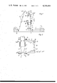
FIG. 1 is a diagrammatic side elevation of a blown film installation with equipment for detecting the thickness tolerances;
FIG. 2 is a diagrammatic representation of the relationship between the thickness measuring apparatus and the setting elements of the cooling sectors at the nozzle ring, and
FIG. 3 is a quantitative representation of the allocation of the individual film sectors to the cooling sectors at the nozzle ring.
In the installation diagrammatically illustrated in FIG. 1, the extruder 1 conveys the thermoplastic melt to be processed through the connector 2 into the film blowhead 3 with the cooling ring 4, where the melt is formed into the tubular film 5. At the level of the rigidification line 6 of the film there is a diagrammatically indicated film calibrating apparatus 7 which determines the diameter of the tubular film and thus the width of the flattened web of film. The tubular film is flattened by means of the flattening plates 8, withdrawn by the take-off rollers 9 and the subsequent reversing rollers and fed as a flattened web 10 of film by way of the guide rollers 11 to the stationary coiler 12 and wound up.
Preferably above the calibrating apparatus 7, the measuring head 14 is disposed on an annular cross-member 15, the arrow 16 indicating the measuring motion through ±360°. To prevent the measuring result from being influenced by twist in the film resulting from the reversing take-off, the reversing motion is stopped shortly before or during the measurement. This interruption of the reversing rotation is acceptable because the reversing speed 16 of the measuring turntable 14, 15 is a multiple of the reversing speed 13 of the reversing take- off apparatus 8, 9. To measure the thickness tolerance profile, the reversing motion of the take- off 8, 9 is momentarily stopped and, after a short holding time which can be larger or smaller depending on the take-off speed of the film and which serves to reduce the angle of twist of the film bubble, the measuring turntable 14, 15 is rotated. Thereafter, the reversing take- off apparatus 8, 9 is restarted. By means of this interruption in the reversing take-off, the quality of coiling does not markedly deteriorate because, on approach of the film thickness tolerances towards zero, one could dispense with the reversing take-off for distributing the thick and thin portions of the film.
A measuring apparatus 14 determining the single film thickness can for example also be disposed in one of the flattening plates 8 at the position 14' or behind the reversing take-off apparatus 9 at a marginal zone of the flattened web 10 of film as a measuring system 14". In the latter case, one measures the double film thickness which can with sufficient accuracy be utilized as the thickness measurement for the single layer of web. The measuring signal of the rotary measuring head 14 is fed by way of the measuring conduit 17 with the cable loop 17' permitting the reversing motion to the thickness profile indicating box 18 and it is represented on the thickness tolerance diagram 19.
The thickness measurement signal can be fed as an electrical value by way of the connecting conduit 20 to a microprocessor 21 which suitably transforms the measuring signals and feeds the setting commands to the setting elements 23' . . . 23n for the cooling sectors by way of the connecting conduits 22', 22" . . . 22n.
After one revolution of the measuring turntable 14, 15, film sectors xF are divided off corresponding to the number of cooling sectors xK and the partial mean values sx ' are formed. The values sx ' are stored in the measuring value memory 21' of the microprocessor 21. By means of the central unit (CPU) of the microprocessor 21, these partial mean values sx ' are related to the line of which the spacing from the 0% line or sm line, i.e. the line corresponding to the mean film diameter, is formed by the value sx.sbsb.max '. In FIG. 3, this applies to the correcting sector 5 which has been emphasized by a circle. By means of the microprocessor 21, one then forms the difference Δsx =sx.sbsb.max '-sx ' and stored in the operating memory of the microprocessor. In the operating memory of the microprocessor, these values likewise represent the course of the tolerance curve 19 of the thickness profle in step form according to the inverse of the partial mean values. One therefore obtains a profile which is related to an 0 line and which defines the starting point for determining the correcting commands for the setting elements.
By means of the microprocessor 21, the differences Δsx are increased over-proportionally at the positions sx '<sm and are under-proportionally transformed at the thick positions with sx '>sm. These values are stored in the operating memory of the microprocessor 21 as recalculated partial mean values sx "' and, after the first measuring cycle, transmitted as setting commands directy to the correcting or cooling sectors associated with the corresponding film sectors. Each measuring cycle is defined by the revolution of the measuring turntable 14, 15.
The cooling sector 5 associated with the film sector having the absolute thick position thus receives no cooling command whereas the cooling sector 10 associated with the film sector having the absolute thin tolerance position receives the largest cooling command.
The turning time of the measuring turntable 14, 15 results in a certain time constant so that it is desirable after several measuring and control cycles, i.e. after a plurality of revolutions of the measuring turntable, to adapt the controlling method to the thickness tolerance profile that has already been improved. For this purpose the thickness tolerance departures are no longer related to the extreme values but to the mean value line (0% or sm) and the tolerance departures that are now still detected are added to or subtracted from the operating memory in the form of small correcting steps. Without any complicated algorithmic control, one thus obtains a quasi constant control behaviour which receives its measured time constant from the turning time of the measuring turntable.
Thus, by defining the reference line through the measuring sector with the maximum tolerance, the entire tolerance range is directly affected under the principle of sector cooling and it is brought to zero in a few steps. Conversely to the previously described method, one can also employ only sector heating and define the reference line to the sector having the minimum tolerance. Similarly, a combination of these two methods can be employed in that as a reference line the measuring values sx ' are related to the mean value sm even during the first revolution of the measuring turntable, the partial mean values being over-proportionally converted at the thin tolerance positions and under-proportionally converted at the thick positions and transferred to the operating memory sx '". Particularly in the latter method, use is made either of the principle of heating/cooling sectors or setting apparatuses actuated by gear motors.
The controlling method does not consider the lateral displacement of the intermediate measuring sectors relatively to the thin or thick positions; however, by reversal of the tolerance profile in the operating memory sx '", one already achieves the final position of the tempering or correcting sectors xK during the first method step with a very good accuracy because the following revolutions of the measuring turntable with the resulting small correcting steps rapidly bring the resulting measuring value departure to zero in steps. In this respect it should be borne in mind that with thickness tolerances near 0% the measuring sectors xF are increasingly more correctly disposed in relation to the correcting sectors xK.
Claims (10)
1. A method of controlling the film thickness at a blown film extruder installation, the installation comprising a nozzle ring for extruding film divided into cooling sectors provided with setting elements, a film calibrating device, and a take-off and coiling apparatus for the film, said method comprising:
measuring thicknesses over the circumference of the extruded film;
forming film sectors of equal circumferential length corresponding to the number of cooling sectors and assigning the film sectors to respective ones of the cooling sectors;
assigning the individual measured thicknesses to the film sectors and determining mean thickness distributions (s'x) for the individual film sectors, the values of the mean thickness distributions (s'x) defining a measure for correcting commands for the setting elements of the cooling sectors that are associated with the respective film sectors;
selecting one of the mean thickness distributions of one of the film sectors as a reference value (s'x max); and
simultaneously generating correcting commands that influence the cooling sectors associated with remaining ones of the film sectors so that the values of the mean thickness distributions of the remaining film sectors approach the reference value to thereby obtain uniform thickness of the extruded film, the size of the correcting commands being so related to the film sector having the selected reference value that the cooling sector associated therewith receives no correcting command and the correcting commands of the other cooling sectors are formed by the respective departure (Δsx) of the mean thickness distribution of the associated film sectors from the extreme reference value of the mean thickness distribution (Δsx =s'x max -s'x), and that by reason of the correcting commands and according to the departure (Δsx), the cooling sectors are cooled when the reference value is a maximum thickness and the cooling sectors are heated when the reference value is a minimum thickness.
2. A method according to claim 1, characterised in that the size of the correcting commands relatively to the departures substantially for all cooling sectors associated with film sectors of which the mean thickness distributions are below the mean film thickness increase over-proportionally up to the cooling sector corresponding to the film sector with a thickness distribution corresponding to the mean film thickness (sm) and, substantially beginning with this cooling sector, increases under-proportionally for the cooling sectors associated with film sectors with thickness distributions over the mean film thickness.
3. A method according to claim 2, characterised in that the size of the correcting commands relatively to the departures increases substantially in the form of an e function.
4. A method according to one of claim 1, characterised in that after a few measuring and control cycles the differences detected from subsequent measurements in the mean thickness distribution of the individual film sectors are subtracted from or added to the mean film thickness of the previously determined departures (Δsx), and that the values so formed define a new measure for the correcting command.
5. A method according to claim 1, characterised in that the value of the thickness distribution corresponding to the mean film thickness is subtracted from the values of the mean thickness distributions for the individual film sectors and this difference defines a measure for the correcting command.
6. A method according to claim 5, characterised in that the cooling sectors associated with the film sectors having thin portions are cooled at the same time as the cooling sectors associated with the film sectors having thick portions are heated.
7. A method according to claim 1, characterised in that the size of the correcting commands relatively to the departures increases substantially in the form of an e function.
8. A method according to claim 1, wherein the reference value is an extreme value representative of maximum thickness.
9. A method according to claim 1, wherein the reference value is an extreme value representative of minimum thickness.
10. A method according to claim 1, wherein the reference value is a value intermediate the maximum thickness and the minimum thickness of the extruded film.
Applications Claiming Priority (2)
| Application Number | Priority Date | Filing Date | Title |
|---|---|---|---|
| DE3002903 | 1980-01-28 | ||
| DE3002903A DE3002903C2 (en) | 1980-01-28 | 1980-01-28 | Method for controlling the film thickness on a blown film extruder |
Related Child Applications (1)
| Application Number | Title | Priority Date | Filing Date |
|---|---|---|---|
| US06/390,543 Continuation US4464318A (en) | 1980-01-28 | 1982-06-21 | Method of controlling the film thickness at a blown film installation |
Publications (1)
| Publication Number | Publication Date |
|---|---|
| US4339404A true US4339404A (en) | 1982-07-13 |
Family
ID=6093065
Family Applications (2)
| Application Number | Title | Priority Date | Filing Date |
|---|---|---|---|
| US06/214,733 Expired - Lifetime US4339404A (en) | 1980-01-28 | 1980-12-09 | Method of controlling the film thickness at a blown film installation |
| US06/390,543 Expired - Lifetime US4464318A (en) | 1980-01-28 | 1982-06-21 | Method of controlling the film thickness at a blown film installation |
Family Applications After (1)
| Application Number | Title | Priority Date | Filing Date |
|---|---|---|---|
| US06/390,543 Expired - Lifetime US4464318A (en) | 1980-01-28 | 1982-06-21 | Method of controlling the film thickness at a blown film installation |
Country Status (11)
| Country | Link |
|---|---|
| US (2) | US4339404A (en) |
| JP (1) | JPS56123826A (en) |
| BR (1) | BR8100137A (en) |
| CA (1) | CA1163066A (en) |
| CH (1) | CH652340A5 (en) |
| DE (1) | DE3002903C2 (en) |
| FI (1) | FI74236C (en) |
| FR (1) | FR2474390A2 (en) |
| GB (1) | GB2070288B (en) |
| IT (1) | IT1134280B (en) |
| SU (1) | SU1132802A3 (en) |
Cited By (9)
| Publication number | Priority date | Publication date | Assignee | Title |
|---|---|---|---|---|
| US4464318A (en) * | 1980-01-28 | 1984-08-07 | Windmoller & Holscher | Method of controlling the film thickness at a blown film installation |
| EP0153511A1 (en) * | 1983-12-27 | 1985-09-04 | Wavin B.V. | Method and apparatus for extruding a plastic pipe with controlled wall thickness |
| US4768940A (en) * | 1985-03-26 | 1988-09-06 | Wavin Bv | Tube wall thickness measuring device and extrusion apparatus with the device |
| US4882104A (en) * | 1987-04-03 | 1989-11-21 | Cincinnati Milacron, Inc. | Method of controlling the thickness of an extruded plastic article |
| US5110518A (en) * | 1989-10-26 | 1992-05-05 | Reifenhauser Gmbh & Co. Maschinenfabrik | Foil-blowing apparatus and method |
| US5288219A (en) * | 1991-03-25 | 1994-02-22 | Battenfeld Gloucester Engineering Co., Inc. | Air ring for controlling blown film thickness |
| US5345399A (en) * | 1992-07-06 | 1994-09-06 | Union Camp Corporation | System and method for monitoring and controlling the width of a product |
| US5676893A (en) * | 1993-12-01 | 1997-10-14 | Addex Design, Inc. | Cooling and thickness control for extruded products |
| CN111565909A (en) * | 2018-01-12 | 2020-08-21 | 科林斯股份公司 | Method for adjusting the profile of a film in a blown extrusion line, related film and reel |
Families Citing this family (13)
| Publication number | Priority date | Publication date | Assignee | Title |
|---|---|---|---|---|
| DE3014989C2 (en) * | 1980-04-18 | 1991-01-24 | Windmöller & Hölscher, 4540 Lengerich | Method for controlling the film thickness on a blown film extruder |
| GB8420761D0 (en) * | 1984-08-15 | 1984-09-19 | Ici Plc | Controlling dynamic instability |
| DE3518155A1 (en) * | 1985-05-21 | 1986-11-27 | Reifenhäuser GmbH & Co Maschinenfabrik, 5210 Troisdorf | METHOD FOR PRODUCING A PLASTIC FILM WITH A LOW THICKNESS TOLERANCE |
| US4753767A (en) * | 1986-04-03 | 1988-06-28 | The Dow Chemical Company | Extrusion apparatus and method |
| US4760627A (en) * | 1987-03-23 | 1988-08-02 | Enrique Schele | Apparatus for an oscillating pinch roll assembly utilized in the extrusion of blown films |
| DE9108417U1 (en) * | 1991-07-08 | 1991-08-29 | Konermann, Stefan, 4540 Lengerich, De | |
| DE19541296C2 (en) * | 1995-11-06 | 1999-07-01 | Windmoeller & Hoelscher | Device for heating the film sectors of a film tube extruded from a film blowing head |
| BR0207792A (en) * | 2001-03-05 | 2004-03-23 | Windmoeller & Hoelscher | Sheet Blowing Head for Tubular Sheet Making |
| CA2355140A1 (en) * | 2001-08-16 | 2003-02-16 | Robert D. Krycki | Motorized air ring |
| DE102009033171B4 (en) * | 2009-07-13 | 2016-03-03 | Hosokawa Alpine Ag | Method for controlling the film thickness of stretched tubular films and apparatus for carrying out the method |
| US11123909B2 (en) | 2013-07-19 | 2021-09-21 | Windmöller & Heilscher KG | Apparatus for producing films stretched in-line |
| DE202013012784U1 (en) | 2013-07-19 | 2019-08-02 | Windmöller & Hölscher Kg | Device for producing inline stretched films |
| CA2974587A1 (en) | 2017-07-27 | 2019-01-27 | Layfield Group Ltd. | Method and apparatus for extruding blown film with a controlled thickness profile |
Citations (9)
| Publication number | Priority date | Publication date | Assignee | Title |
|---|---|---|---|---|
| US3307215A (en) * | 1964-04-09 | 1967-03-07 | Industrial Nucleonics Corp | Control apparatus for industrial apparatus |
| US3510374A (en) * | 1964-04-20 | 1970-05-05 | Industrial Nucleonics Corp | Method and control apparatus for regulating apparatuses |
| DE2140194A1 (en) * | 1971-08-11 | 1973-02-22 | Basf Ag | RING NOZZLE FOR EXTRUSION PRESSES |
| US3768949A (en) * | 1970-07-17 | 1973-10-30 | Windmoeller & Hoelscher | Flattening and take-off apparatus for blown tubular plastics film |
| US3775035A (en) * | 1970-01-12 | 1973-11-27 | Owens Illinois Inc | Foam plastic extrusion apparatus with plurality of die lip temperature controls |
| US3974248A (en) * | 1972-09-08 | 1976-08-10 | Bakelite Xylonite Limited | Profile determining and/or controlling system |
| US4189288A (en) * | 1977-05-13 | 1980-02-19 | Reifenhauser Kg | Apparatus for producing blown synthetic-resin foils and films |
| US4209475A (en) * | 1978-10-20 | 1980-06-24 | Mobil Oil Corporation | Method and apparatus for effecting uniform film thickness |
| US4246212A (en) * | 1978-04-17 | 1981-01-20 | Windmoller & Holscher | Method and apparatus for optimizing the output of a blown film extruder plant by means of a process computer |
Family Cites Families (10)
| Publication number | Priority date | Publication date | Assignee | Title |
|---|---|---|---|---|
| GB1054989A (en) * | 1964-09-17 | 1900-01-01 | ||
| US3438088A (en) * | 1967-01-19 | 1969-04-15 | Beloit Corp | Control for maintaining uniform gauge on blown film |
| DE2232930A1 (en) * | 1971-07-06 | 1973-02-01 | Hepworth Plastics Ltd | METHOD AND DEVICE FOR THE PRODUCTION OF PIPES OF EQUAL WALL THICKNESS IN THE EXTRUSION PROCESS |
| DE2553069C3 (en) * | 1974-11-27 | 1981-05-27 | Teijin Ltd., Osaka | Slot nozzle for producing a polymer film of uniform thickness |
| AT362922B (en) * | 1975-02-26 | 1981-06-25 | Cincinnati Milacron Austria | EXTRUSION |
| DE2658518C2 (en) * | 1976-12-23 | 1983-04-28 | Reifenhäuser KG, 5210 Troisdorf | Plant for the production of blown films made of thermoplastic material |
| DE2723991A1 (en) * | 1977-05-27 | 1978-11-30 | Ver Foerderung Inst Kunststoff | Annular plastic extrusion nozzle control - for uniform pressure distribution with pressure pick=ups and computer |
| DE2947293C2 (en) * | 1979-11-23 | 1983-09-15 | Windmöller & Hölscher, 4540 Lengerich | Process for regulating the film thickness on a blown film extruder |
| DE2950003C2 (en) * | 1979-12-12 | 1983-08-11 | Windmöller & Hölscher, 4540 Lengerich | Process for regulating the film thickness on a blown film extruder |
| DE3002903C2 (en) * | 1980-01-28 | 1986-12-04 | Windmöller & Hölscher, 4540 Lengerich | Method for controlling the film thickness on a blown film extruder |
-
1980
- 1980-01-28 DE DE3002903A patent/DE3002903C2/en not_active Expired
- 1980-11-14 IT IT25991/80A patent/IT1134280B/en active
- 1980-12-03 FI FI803765A patent/FI74236C/en not_active IP Right Cessation
- 1980-12-05 FR FR8025823A patent/FR2474390A2/en active Granted
- 1980-12-09 US US06/214,733 patent/US4339404A/en not_active Expired - Lifetime
- 1980-12-15 GB GB8040093A patent/GB2070288B/en not_active Expired
- 1980-12-19 SU SU803250656A patent/SU1132802A3/en active
-
1981
- 1981-01-09 CA CA000368211A patent/CA1163066A/en not_active Expired
- 1981-01-12 BR BR8100137A patent/BR8100137A/en not_active IP Right Cessation
- 1981-01-27 JP JP1073081A patent/JPS56123826A/en active Pending
- 1981-01-28 CH CH563/81A patent/CH652340A5/en not_active IP Right Cessation
-
1982
- 1982-06-21 US US06/390,543 patent/US4464318A/en not_active Expired - Lifetime
Patent Citations (9)
| Publication number | Priority date | Publication date | Assignee | Title |
|---|---|---|---|---|
| US3307215A (en) * | 1964-04-09 | 1967-03-07 | Industrial Nucleonics Corp | Control apparatus for industrial apparatus |
| US3510374A (en) * | 1964-04-20 | 1970-05-05 | Industrial Nucleonics Corp | Method and control apparatus for regulating apparatuses |
| US3775035A (en) * | 1970-01-12 | 1973-11-27 | Owens Illinois Inc | Foam plastic extrusion apparatus with plurality of die lip temperature controls |
| US3768949A (en) * | 1970-07-17 | 1973-10-30 | Windmoeller & Hoelscher | Flattening and take-off apparatus for blown tubular plastics film |
| DE2140194A1 (en) * | 1971-08-11 | 1973-02-22 | Basf Ag | RING NOZZLE FOR EXTRUSION PRESSES |
| US3974248A (en) * | 1972-09-08 | 1976-08-10 | Bakelite Xylonite Limited | Profile determining and/or controlling system |
| US4189288A (en) * | 1977-05-13 | 1980-02-19 | Reifenhauser Kg | Apparatus for producing blown synthetic-resin foils and films |
| US4246212A (en) * | 1978-04-17 | 1981-01-20 | Windmoller & Holscher | Method and apparatus for optimizing the output of a blown film extruder plant by means of a process computer |
| US4209475A (en) * | 1978-10-20 | 1980-06-24 | Mobil Oil Corporation | Method and apparatus for effecting uniform film thickness |
Non-Patent Citations (2)
| Title |
|---|
| Article entitled "Moglickkeiten der Prozessbrechneranwendung bel Flachfolien-und Tafelextrusionsanlagen," published 1978. * |
| Article entitled "Prozessregler in der Extrusionstechnik", published 1976. * |
Cited By (11)
| Publication number | Priority date | Publication date | Assignee | Title |
|---|---|---|---|---|
| US4464318A (en) * | 1980-01-28 | 1984-08-07 | Windmoller & Holscher | Method of controlling the film thickness at a blown film installation |
| EP0153511A1 (en) * | 1983-12-27 | 1985-09-04 | Wavin B.V. | Method and apparatus for extruding a plastic pipe with controlled wall thickness |
| US4768940A (en) * | 1985-03-26 | 1988-09-06 | Wavin Bv | Tube wall thickness measuring device and extrusion apparatus with the device |
| US4882104A (en) * | 1987-04-03 | 1989-11-21 | Cincinnati Milacron, Inc. | Method of controlling the thickness of an extruded plastic article |
| US5110518A (en) * | 1989-10-26 | 1992-05-05 | Reifenhauser Gmbh & Co. Maschinenfabrik | Foil-blowing apparatus and method |
| US5288219A (en) * | 1991-03-25 | 1994-02-22 | Battenfeld Gloucester Engineering Co., Inc. | Air ring for controlling blown film thickness |
| US5345399A (en) * | 1992-07-06 | 1994-09-06 | Union Camp Corporation | System and method for monitoring and controlling the width of a product |
| US5676893A (en) * | 1993-12-01 | 1997-10-14 | Addex Design, Inc. | Cooling and thickness control for extruded products |
| CN111565909A (en) * | 2018-01-12 | 2020-08-21 | 科林斯股份公司 | Method for adjusting the profile of a film in a blown extrusion line, related film and reel |
| CN111565909B (en) * | 2018-01-12 | 2022-06-03 | 科林斯股份公司 | Method for adjusting the profile of a film in a blown extrusion line, related film and reel |
| US11590680B2 (en) * | 2018-01-12 | 2023-02-28 | Colines S.P.A. | Method for adjusting the profile of a film in blown extrusion lines, adjusted film and reel |
Also Published As
| Publication number | Publication date |
|---|---|
| JPS56123826A (en) | 1981-09-29 |
| DE3002903C2 (en) | 1986-12-04 |
| FR2474390A2 (en) | 1981-07-31 |
| GB2070288A (en) | 1981-09-03 |
| SU1132802A3 (en) | 1984-12-30 |
| CH652340A5 (en) | 1985-11-15 |
| IT1134280B (en) | 1986-08-13 |
| FI74236C (en) | 1988-01-11 |
| FR2474390B1 (en) | 1984-06-29 |
| CA1163066A (en) | 1984-03-06 |
| DE3002903A1 (en) | 1981-08-06 |
| BR8100137A (en) | 1981-07-28 |
| IT8025991A0 (en) | 1980-11-14 |
| FI803765L (en) | 1981-07-29 |
| GB2070288B (en) | 1983-11-23 |
| FI74236B (en) | 1987-09-30 |
| US4464318A (en) | 1984-08-07 |
Similar Documents
| Publication | Publication Date | Title |
|---|---|---|
| US4339404A (en) | Method of controlling the film thickness at a blown film installation | |
| US4351785A (en) | Method of controlling the film thickness at a blown film extruder installation | |
| US4339403A (en) | Method of controlling the film thickness at a blown film extruder installation | |
| US4886438A (en) | Method and apparatus of extruding a plastic pipe under control of the wall thickness of the extruded plastic pipe | |
| US4426239A (en) | Method of controlling the film thickness of flat films produced in flat film extruder installations | |
| EP0287551B1 (en) | Method of controlling the thickness of an extruded plastic article | |
| US5498145A (en) | Control system for controlling the outer diameter of a strand of plastic material, in particular of a cable | |
| US3782873A (en) | Thickness control apparatus for polymeric film structures | |
| JPH0141487B2 (en) | ||
| US5410786A (en) | Process and arrangement for the warping of threads onto a drum having a conical surface | |
| SE502508C2 (en) | Control system and method of coating a body with a tread | |
| CN101583477A (en) | Method for the operation of a production plant to produce an extrudate | |
| FI94989C (en) | secondary coating | |
| US3649726A (en) | Method for controlling the thickness of polymeric film structures | |
| US4592881A (en) | Method for controlling a foam resin cable coating extrusion process | |
| US5135689A (en) | Method of measuring thickness of extruded films | |
| US5976449A (en) | Method and apparatus for the cross-sectional measurement of electric insulated conductors | |
| CA2030843A1 (en) | Process of controlling the film thickness of blow-formed and axially and preferably biaxially stretched tubular films | |
| GB2130763A (en) | Method and apparatus for controlling a cellular foam cable coating extrusion process | |
| EP0823319A1 (en) | Method for regulating the thickness of a blown tubular film in a blow moulding system | |
| JPH0320845B2 (en) | ||
| JPH0737456A (en) | Control system of outer diameter of electric wire by fuzzy control | |
| JP2000326392A (en) | Method and apparatus for producing long molded object | |
| JPH0618091B2 (en) | Method for manufacturing foam insulated wire | |
| JPH0581430B2 (en) |
Legal Events
| Date | Code | Title | Description |
|---|---|---|---|
| STCF | Information on status: patent grant |
Free format text: PATENTED CASE |