US4328608A - Pipeline building method and apparatus - Google Patents
Pipeline building method and apparatus Download PDFInfo
- Publication number
- US4328608A US4328608A US06/156,739 US15673980A US4328608A US 4328608 A US4328608 A US 4328608A US 15673980 A US15673980 A US 15673980A US 4328608 A US4328608 A US 4328608A
- Authority
- US
- United States
- Prior art keywords
- pipe
- gripper
- coupling
- fixture
- main frame
- Prior art date
- Legal status (The legal status is an assumption and is not a legal conclusion. Google has not performed a legal analysis and makes no representation as to the accuracy of the status listed.)
- Expired - Lifetime
Links
Images


Classifications
-
- B—PERFORMING OPERATIONS; TRANSPORTING
- B21—MECHANICAL METAL-WORKING WITHOUT ESSENTIALLY REMOVING MATERIAL; PUNCHING METAL
- B21D—WORKING OR PROCESSING OF SHEET METAL OR METAL TUBES, RODS OR PROFILES WITHOUT ESSENTIALLY REMOVING MATERIAL; PUNCHING METAL
- B21D39/00—Application of procedures in order to connect objects or parts, e.g. coating with sheet metal otherwise than by plating; Tube expanders
- B21D39/04—Application of procedures in order to connect objects or parts, e.g. coating with sheet metal otherwise than by plating; Tube expanders of tubes with tubes; of tubes with rods
-
- B—PERFORMING OPERATIONS; TRANSPORTING
- B23—MACHINE TOOLS; METAL-WORKING NOT OTHERWISE PROVIDED FOR
- B23P—METAL-WORKING NOT OTHERWISE PROVIDED FOR; COMBINED OPERATIONS; UNIVERSAL MACHINE TOOLS
- B23P19/00—Machines for simply fitting together or separating metal parts or objects, or metal and non-metal parts, whether or not involving some deformation; Tools or devices therefor so far as not provided for in other classes
- B23P19/02—Machines for simply fitting together or separating metal parts or objects, or metal and non-metal parts, whether or not involving some deformation; Tools or devices therefor so far as not provided for in other classes for connecting objects by press fit or for detaching same
-
- Y—GENERAL TAGGING OF NEW TECHNOLOGICAL DEVELOPMENTS; GENERAL TAGGING OF CROSS-SECTIONAL TECHNOLOGIES SPANNING OVER SEVERAL SECTIONS OF THE IPC; TECHNICAL SUBJECTS COVERED BY FORMER USPC CROSS-REFERENCE ART COLLECTIONS [XRACs] AND DIGESTS
- Y10—TECHNICAL SUBJECTS COVERED BY FORMER USPC
- Y10T—TECHNICAL SUBJECTS COVERED BY FORMER US CLASSIFICATION
- Y10T29/00—Metal working
- Y10T29/53—Means to assemble or disassemble
- Y10T29/5367—Coupling to conduit
-
- Y—GENERAL TAGGING OF NEW TECHNOLOGICAL DEVELOPMENTS; GENERAL TAGGING OF CROSS-SECTIONAL TECHNOLOGIES SPANNING OVER SEVERAL SECTIONS OF THE IPC; TECHNICAL SUBJECTS COVERED BY FORMER USPC CROSS-REFERENCE ART COLLECTIONS [XRACs] AND DIGESTS
- Y10—TECHNICAL SUBJECTS COVERED BY FORMER USPC
- Y10T—TECHNICAL SUBJECTS COVERED BY FORMER US CLASSIFICATION
- Y10T29/00—Metal working
- Y10T29/53—Means to assemble or disassemble
- Y10T29/53796—Puller or pusher means, contained force multiplying operator
- Y10T29/5383—Puller or pusher means, contained force multiplying operator having fluid operator
Definitions
- the present disclosure provides method and apparatus by which the marginal end of a pipe can be forced axially into a coupling member made in accordance with my co-pending patent application.
- Pipeline building method and apparatus comprising gripping a marginal length of a pipe joint, capturing a pipe coupling within a fixture, moving the pipe joint axially towards the coupling until a marginal length of the pipe joint has been forced into the coupling.
- the coupling is provided with circumferentially extending grooves which grip the pipe joint with great force, and an epoxy resin is applied between the pipe joint and the coupling for sealing and bonding one to the other.
- the apparatus of this invention comprises a main frame which supportingly receives a marginal length of a pipeline during construction thereof.
- a fixture is supported by the main frame, and a pipe coupling is releasably held by the fixture.
- a pipe gripper has pipe dies which grip a marginal length of a pipe joint.
- a powerful hydraulic cylinder assembly moves the pipe gripper towards the fixture to cause a marginal end of the pipe joint to be received within the coupling.
- Remote, actuated, hydraulic cylinder assemblies actuate the pipe gripper and fixture between an opened and closed configuration.
- a coupling is placed on a joint of pipe.
- the pipeline is fabricated with the coupling forming the end of the pipeline. So the boxed end of the last pipe joint forms the terminal end of the pipeline, and the pin end of a pipe joint is applied to the boxed end of the pipeline as the fabrication of the pipeline progresses.
- a primary object of this invention is the provision of both method and apparatus by which a pipeline can be fabricated without welding or screwing the pipe joints together, by moving a pin end of a pipe joint axially and forcibly into a box end of another pipe joint.
- Another object of the present invention is the provision of apparatus for forcing the pin end of a pipe joint axially into the box end of another pipe joint so that the resultant structure presents a pipeline which requires no welding or screwing of one coacting member to another.
- a further object of this invention is the provision of a frame mounted device for manipulating pipe joints in a manner to force a pin end of a pipe joint axially into the box end of another pipe joint so that the resultant series connected pipe joints provide a pipeline which requires no relative turning of one joint about the axial centerline of another joint.
- Another and still further object of this invention is the provision of two spaced relatively movable devices for fabricating a pipeline, wherein one device grips a marginal length of a pipe joint while the other device captures a coupling member, and the pin end of the pipe joint is forced axially into the box end of another pipe joint, as the pipeline undergoes construction.
- FIG. 1 is a fragmented, part cross-sectional view of a pipeline fabricated in accordance with my co-pending patent application Ser. No. 048,780 filed June 15, 1979;
- FIG. 2 is a diagrammatical representation of apparatus for fabricating the pipeline of FIG. 1;
- FIG. 3 is a perspective view of apparatus made in accordance with the present invention.
- FIG. 4 is a top, plan view of the apparatus disclosed in FIG. 3, with some parts being removed therefrom in order to more clearly disclose some of the details thereof;
- FIG. 5 is a side elevational view of the apparatus disclosed in FIG. 4;
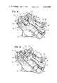
- FIG. 6 is a perspective view of the apparatus disclosed in FIGS. 3-5;
- FIG. 7 is another perspective view of the apparatus seen in FIG. 6;
- FIG. 8 is a fragmentary, detail of part of the apparatus disclosed in FIG. 7;
- FIG. 9 shows the apparatus of FIG. 8 in another operative configuration
- FIG. 10 is an enlarged, cross-sectional view taken along line 10--10 of FIG. 4;
- FIG. 11 is a fragmentary, part cross-sectional, top view of the apparatus seen in FIG. 10;
- FIG. 12 is an enlarged, fragmented, cross-sectional representation of part of the apparatus seen in FIG. 11.
- FIG. 1 discloses a section of a pipeline made up of joints of pipe 11 having the marginal ends thereof forced along the longitudinal axial centerline and into the interior of a coupling 12 in accordance with my co-pending patent application Ser. No. 048,780 filed June 15, 1979.
- the marginal ends 14 of the pipe are not threaded in the conventional manner, but instead the interface between the pipe end and the coupling are held together by high frictional forces brought about by force-fitting the end of the pipe into a specially grooved inner surface of the coupling member.
- Numeral 15 indicates opposed shoulders formed by the opposite ends of coupling 12.
- the apparatus 16 of this invention includes a main framework having longitudinally disposed skids 18 and 19 which are rigidly tied together by spaced, lateral frame members 20 and 22. Longitudinally disposed parallel guide means in the form of polished guide rods 24 and 26 are supported from the main frame by attaching the opposed marginal ends of the rods to the lateral members as indicated by numerals 28, 29, 30, and 31 in FIG. 4.
- a pipe gripper 32 is slidably mounted for low friction, longitudinal movement on the guide rods, with there being opposed hydraulic cylinder assemblies 34 and 36 connected between the pipe gripper and the main frame, so that the pistons 35 and 37 thereof can force the pipe gripper to reciprocate axially respective to a pipe being made up into a pipeline.
- a bifold slip assembly 38 provides a gripping action about an exterior marginal surface of a pipe, as will be more fully discussed later on in this disclosure.
- a fixture 40 for releasably holding a coupling is supported by the lateral frame member 22 such that the axial centerline 42 of the fixture and the pipe gripper lie along a common axial centerline.
- the fixture is held in fixed relationship respective to the main framework.
- the pipe gripper includes doors 43 and 43' having hinges 44 and 46 by which the doors may be folded away from and toward the centerline 42. Lugs 45 and 47 are attached to the bifold doors, while spaced ears at 48 and 50 are attached to the gripper so that a hydraulically actuated cylinder can be placed between the ears and the lugs for actuating the bifold doors between a closed, or pipe gripping position, and an opened, or pipe releasing position.
- the door 40 of the coupling fixture is hinged at 52 and includes a lug 54 spaced from a pair of ears 56 to enable a hydraulically actuated cylinder assembly to be interposed therebetween, thereby actuating the door 40 from the closed, or coupling gripping position, to the opened, or coupling releasing position, and vice versa.
- FIG. 3 illustrates that the apparatus of the present invention may be provided with a centilever overhanging structure 58 by which the entire apparatus can be hoisted by attachment of a suitable lifting means to the apertured plate member 60.
- the plate member is located at the static center of gravity.
- Cylinders 62 and 64 are connected between lugs and ears 45, 48 and 47, 50, respectively, for actuating the bifold doors of the pipe gripper 38.
- the cylinders preferably are pivotally connected to the ears 48 and 50, while the pistons are connected to the lugs 45 and 47.
- Hydraulic cylinder assembly 66 is connected between lugs 54 and ears 56 of the door 40. Suitable hydraulic lines are connected between a control console at 68 and the various hydraulic cylinders so that each of the cylinders can be remotely actuated at a safe distance away from the moving parts of the mechanism.
- a marginal length of a joint of pipe has been received within the pipe gripper apparatus 32, and in FIG. 9, the gripper jaws have been actuated from the opened to the closed position by the hydraulic cylinders 62 and 64 to thereby secure the pipe joint to the traveling pipe gripper with great force.
- the marginal pin end of the pipe is disposed in close proximity to a coupling 12 located within the coupling holding fixture 40.
- the fixture includes a large id. portion 70 and a small id. portion 72.
- the large id. portion snugly encapsulates the exterior of a coupling, with a marginal end of the coupling being directed towards the pin end of the pipe 11, and with the shoulder 74, which is formed between members 70 and 72, engaging the entire shoulder 15 at one end of the coupling.
- the small id. member 72 of the fixture bears against a pipe which may be contained within the near end of the coupling of FIGS. 8 and 9, and which forms part of the completed pipeline.
- Actuation of the cylinders 34 and 36 extends pistons 35 and 37 thereof, thereby causing the pipe gripper to move with great force towards the fixture until the pin end of the pipe joint is forced into the coupling, or box end of the pipeline, which ever the case may be. It is advantageous to apply apoxy resin to the marginal pipe end as noted at 75 in FIG. 2 to provide a sealed bond therebetween.
- the cylinders 62, 64, and 66 are actuated to open the doors and release the assembled pipe and coupling, whereupon the machine can be moved into proper position for connecting the next joint of pipe into the pipeline.
- the preferred embodiment of the invention is carried out by installing couplings on one end of a number of pipe joints in the illustrated manner of FIGS. 7 and 9 so as to eliminate the necessity of carrying out this step in the field.
- This action provides pipe joints having a pin end and a box end.
- the apparatus of this invention is skidded along the projected path of the pipeline, with the two longitudinally disposed skids straddling the pipeline ditch. This is best accomplished by lifting the apparatus at 60 by employment of a side boom tractor or the like.
- a coupling always terminates the pipeline, that is, as joints, of pipe are coupled together, the pin end of the new joint is always mated to the box end of the last connected joint.
- the pipeline is built with the gripping device being at the forward end of the apparatus. Therefore, the machine is positioned so that the box end of the pipeline is received in the fixture in a manner similar to the illustration seen in FIGS. 2, 3, and 8.
- the movable wall 40 is closed by actuating the hydraulic cylinder 66, thereby capturing the last coupling within the fixture.
- a new joint of pipe is placed within the gripping device with the pin end thereof being placed adjacent to the box end of the pipeline.
- the doors are closed by actuating the hydraulic cylinders 62 and 64, thereby gripping the pipe with great force.
- the hydraulic clyinders 34 and 36 are next actuated to move the pipe gripper device towards the fixture, thereby forcing the pin end of the pipe joint into the box end of the pipeline, and completing the connection between the last joint of the pipeline.
- the pistons of the cylinder assemblies are all reciprocated to cause them to stroke in the opposite direction. This action opens the jaws of the gripper device and the door of the fixture, while simultaneously the gripper device moves away from the fixture, and the apparatus is repositioned to cause the last coupling of the pipe line to lie within the fixture.
- the above sequence of manipulative steps is repeated each time an additional joint of pipe is added to the pipeline.
- the diameter of the gripper device and the fixture must be changed in order to accommodate different diameter of pipe.
- the present invention couples pipe together in a rapid and safe manner.
- a considerable savings in the cost of a pipeline is realized by employment of the present method as contrasted to welded or screwed pipe.
- the outer pipe surface is subjected to less damage as compared to other similar methods.
- the pipe gripper bifold doors cooperate with a lower semicircular die 76 to present a gripping surface 77, and which cooperates with gripping surfaces 78, and 80 to enclose the entire outer periphery of a marginal length of pipe 11 when doors 43 and 43' are closed by hydraulic cylinders 62 and 64 of FIG. 7.
- the inner surface of the coacting members 76, 78, and 80 are machined to present circumferentially extending gripping teeth, as seen at 76 in FIG. 11, which engage the outer surface of the pipe 0.020-0.040 inches in depth.
- the doors 43 and 43' are allowed to close to a definite position, and at this position the saw-toothed cutting edges dig a limited depth into the pipe surface.
- the area of damage underlying the gripping members 76, 78, and 80 is within the design tolerance of the pipe and is less damaging than would be realized from making up threaded pipe joints of the same pipe material.
- the teeth may be cut into the gripping surface of the three members as a continuous thread which spirals from one to the other end of the gripping surface, or the teeth may be endless and adjacent to one another. It is important that the teeth be arranged to dig into the pipe when moved towards the fixture.
- Plastic coated pipe and coupling members are assembled together to provide a pipeline having a continuous, undamaged internal coating which cannot be achieved by other known methods.
- the present invention can be practiced in conjunction with upset tubular goods, that is, a pipe joint having an enlarged end sized to receive the opposed, relatively smaller end, and wherein one of the marginal pipe ends of a pipe joint have been provided with the aforementioned co-acting gripping surfaces, as seen at 75 in FIG. 2, for example.
- the box or upset end of the pipe is forced to receive the pin end of another pipe joint therewithin, when the fixture and pipe gripper are forced towards one another.
- Such a pipe joint is contemplated for use in the present apparatus.
Landscapes
- Engineering & Computer Science (AREA)
- Mechanical Engineering (AREA)
- Lining Or Joining Of Plastics Or The Like (AREA)
- Supports For Pipes And Cables (AREA)
Abstract
Description
Claims (5)
Priority Applications (6)
| Application Number | Priority Date | Filing Date | Title |
|---|---|---|---|
| US06/156,739 US4328608A (en) | 1980-06-05 | 1980-06-05 | Pipeline building method and apparatus |
| CA000378355A CA1174439A (en) | 1980-06-05 | 1981-05-26 | Pipeline building method and apparatus |
| MX187499A MX155880A (en) | 1980-06-05 | 1981-05-27 | IMPROVEMENTS IN APPARATUS TO BUILD A PIPE |
| AU71164/81A AU545297B2 (en) | 1980-06-05 | 1981-05-29 | Pipe joining + pipe line assembling apparatus |
| ES502765A ES8303652A1 (en) | 1980-06-05 | 1981-06-04 | Pipeline building method and apparatus |
| GB8117094A GB2077381B (en) | 1980-06-05 | 1981-06-04 | Pipe joining and pipeline fabricating apparatus |
Applications Claiming Priority (1)
| Application Number | Priority Date | Filing Date | Title |
|---|---|---|---|
| US06/156,739 US4328608A (en) | 1980-06-05 | 1980-06-05 | Pipeline building method and apparatus |
Publications (1)
| Publication Number | Publication Date |
|---|---|
| US4328608A true US4328608A (en) | 1982-05-11 |
Family
ID=22560875
Family Applications (1)
| Application Number | Title | Priority Date | Filing Date |
|---|---|---|---|
| US06/156,739 Expired - Lifetime US4328608A (en) | 1980-06-05 | 1980-06-05 | Pipeline building method and apparatus |
Country Status (6)
| Country | Link |
|---|---|
| US (1) | US4328608A (en) |
| AU (1) | AU545297B2 (en) |
| CA (1) | CA1174439A (en) |
| ES (1) | ES8303652A1 (en) |
| GB (1) | GB2077381B (en) |
| MX (1) | MX155880A (en) |
Cited By (10)
| Publication number | Priority date | Publication date | Assignee | Title |
|---|---|---|---|---|
| US4955122A (en) * | 1989-09-27 | 1990-09-11 | Nippon Air Brake Co., Ltd. | Lock unit for a fluid coupling apparatus |
| US4956904A (en) * | 1987-12-29 | 1990-09-18 | Mie Horo Co., Ltd. | Device for joining piping materials |
| US5079816A (en) * | 1990-09-20 | 1992-01-14 | Electric Power Research Institute, Inc. | Positive seal coupling internal joining press |
| US5117546A (en) * | 1991-06-17 | 1992-06-02 | Bethlehem Steel Corporation | Apparatus and method for replacing a bull gear on a trunnion |
| US5184391A (en) * | 1990-09-20 | 1993-02-09 | Electric Power Research Institute, Inc. | Process of press fitting pipe sections together to form a pipeline |
| US5659938A (en) * | 1993-05-27 | 1997-08-26 | Pyron; Donald | Translational press and mandrel apparatus for straightening baghouse cages |
| US20060037474A1 (en) * | 2004-08-23 | 2006-02-23 | Pyron Donald R | Converting twist-lock tube sheet filter orifices to snap-band orifices |
| CN103358120A (en) * | 2013-07-05 | 2013-10-23 | 无锡商业职业技术学院 | Electric pipe fitting butting device |
| US9310007B2 (en) | 2013-04-18 | 2016-04-12 | Marubeni-Itochu Tubulars America Inc. | Positive seal coupling system |
| US10684593B2 (en) | 2014-10-12 | 2020-06-16 | Larry W. Vincent | Systems for data monitoring and management of pipelines assembled with mechanical press fit pipe joints |
Families Citing this family (5)
| Publication number | Priority date | Publication date | Assignee | Title |
|---|---|---|---|---|
| GB2198203B (en) * | 1986-12-02 | 1991-02-20 | Michael Johannes Landman | Separating and drawing together pipe flanges |
| GB2215798A (en) * | 1988-03-26 | 1989-09-27 | John Clements | Pipe jointing tool |
| GB2240599A (en) * | 1989-09-29 | 1991-08-07 | Welsh Water Plc | Apparatus and fitting for coupling plastics pipes |
| IL177036A (en) | 2006-07-23 | 2011-05-31 | Sagiv Agudah Shitufit Chaklait Be Am | Device and method for coupling a pipe fitting to a pipe |
| CN113020803B (en) * | 2021-03-04 | 2023-03-14 | 江西红睿马钢管股份有限公司 | Control system for steel pipe assembling and machining |
Citations (6)
| Publication number | Priority date | Publication date | Assignee | Title |
|---|---|---|---|---|
| US1894835A (en) * | 1928-09-13 | 1933-01-17 | Frank H Smith | Method of and apparatus for joining pipes |
| US3717920A (en) * | 1971-03-25 | 1973-02-27 | Cameron Iron Works Inc | Apparatus for making an underwater pipeline connection |
| US3727289A (en) * | 1969-09-18 | 1973-04-17 | Messer Griesheim Gmbh | A device for clamping and moving together thermoplastic pipes for flush-welding |
| DE2433946A1 (en) * | 1974-07-15 | 1976-02-05 | Zoll | Device for joining and separating large plastic pipes - applies tension to clamps to reduce pipe diameters |
| SU621844A1 (en) * | 1976-06-17 | 1978-08-30 | Научно-Исследовательский Институт Строительного Производства | Device for laying and joining bell-mouth pipes |
| US4189817A (en) * | 1978-03-03 | 1980-02-26 | Moebius Kurt Otto | Hydraulic assembly tool for tube fittings |
-
1980
- 1980-06-05 US US06/156,739 patent/US4328608A/en not_active Expired - Lifetime
-
1981
- 1981-05-26 CA CA000378355A patent/CA1174439A/en not_active Expired
- 1981-05-27 MX MX187499A patent/MX155880A/en unknown
- 1981-05-29 AU AU71164/81A patent/AU545297B2/en not_active Ceased
- 1981-06-04 ES ES502765A patent/ES8303652A1/en not_active Expired
- 1981-06-04 GB GB8117094A patent/GB2077381B/en not_active Expired
Patent Citations (6)
| Publication number | Priority date | Publication date | Assignee | Title |
|---|---|---|---|---|
| US1894835A (en) * | 1928-09-13 | 1933-01-17 | Frank H Smith | Method of and apparatus for joining pipes |
| US3727289A (en) * | 1969-09-18 | 1973-04-17 | Messer Griesheim Gmbh | A device for clamping and moving together thermoplastic pipes for flush-welding |
| US3717920A (en) * | 1971-03-25 | 1973-02-27 | Cameron Iron Works Inc | Apparatus for making an underwater pipeline connection |
| DE2433946A1 (en) * | 1974-07-15 | 1976-02-05 | Zoll | Device for joining and separating large plastic pipes - applies tension to clamps to reduce pipe diameters |
| SU621844A1 (en) * | 1976-06-17 | 1978-08-30 | Научно-Исследовательский Институт Строительного Производства | Device for laying and joining bell-mouth pipes |
| US4189817A (en) * | 1978-03-03 | 1980-02-26 | Moebius Kurt Otto | Hydraulic assembly tool for tube fittings |
Cited By (16)
| Publication number | Priority date | Publication date | Assignee | Title |
|---|---|---|---|---|
| US4956904A (en) * | 1987-12-29 | 1990-09-18 | Mie Horo Co., Ltd. | Device for joining piping materials |
| US4955122A (en) * | 1989-09-27 | 1990-09-11 | Nippon Air Brake Co., Ltd. | Lock unit for a fluid coupling apparatus |
| US5079816A (en) * | 1990-09-20 | 1992-01-14 | Electric Power Research Institute, Inc. | Positive seal coupling internal joining press |
| WO1992005010A1 (en) * | 1990-09-20 | 1992-04-02 | Electric Power Research Institute, Inc. | Positive seal coupling internal joining press |
| US5184391A (en) * | 1990-09-20 | 1993-02-09 | Electric Power Research Institute, Inc. | Process of press fitting pipe sections together to form a pipeline |
| US5117546A (en) * | 1991-06-17 | 1992-06-02 | Bethlehem Steel Corporation | Apparatus and method for replacing a bull gear on a trunnion |
| US5659938A (en) * | 1993-05-27 | 1997-08-26 | Pyron; Donald | Translational press and mandrel apparatus for straightening baghouse cages |
| US7404244B2 (en) | 2004-08-23 | 2008-07-29 | Pyron Donald R | Converting twist-lock tube sheet filter orifices to snap-band orifices |
| US20060037474A1 (en) * | 2004-08-23 | 2006-02-23 | Pyron Donald R | Converting twist-lock tube sheet filter orifices to snap-band orifices |
| US9310007B2 (en) | 2013-04-18 | 2016-04-12 | Marubeni-Itochu Tubulars America Inc. | Positive seal coupling system |
| US9453602B2 (en) | 2013-04-18 | 2016-09-27 | Marubeni-Itochu Tubulars America Inc. | Positive seal coupling system |
| CN103358120A (en) * | 2013-07-05 | 2013-10-23 | 无锡商业职业技术学院 | Electric pipe fitting butting device |
| US10684593B2 (en) | 2014-10-12 | 2020-06-16 | Larry W. Vincent | Systems for data monitoring and management of pipelines assembled with mechanical press fit pipe joints |
| US10732580B2 (en) | 2014-10-12 | 2020-08-04 | Larry W. Vincent | Processes for preparing, forming and assembling pipe sections in a pipeline using mechanical press fit pipe joints |
| US10732579B2 (en) | 2014-10-12 | 2020-08-04 | Larry W. Vincent | Apparatus and method for assembling, measuring, and monitoring integrity of mechanical pipe joints |
| US10732581B2 (en) | 2014-10-12 | 2020-08-04 | Larry W. Vincent | Process for forming and assembling pipe sections using mechanical press fit pipe joints in a pipeline |
Also Published As
| Publication number | Publication date |
|---|---|
| MX155880A (en) | 1988-02-08 |
| ES502765A0 (en) | 1983-02-01 |
| AU7116481A (en) | 1981-12-10 |
| AU545297B2 (en) | 1985-07-11 |
| GB2077381A (en) | 1981-12-16 |
| GB2077381B (en) | 1984-05-16 |
| ES8303652A1 (en) | 1983-02-01 |
| CA1174439A (en) | 1984-09-18 |
Similar Documents
| Publication | Publication Date | Title |
|---|---|---|
| US4328608A (en) | Pipeline building method and apparatus | |
| DE19617156C2 (en) | Blowout preventer plunger for pipe coils | |
| US4940095A (en) | Deployment/retrieval method and apparatus for well tools used with coiled tubing | |
| US4345361A (en) | Tool for joining pipes | |
| EP2606198B1 (en) | Blowout preventer with shearing blades and method | |
| US9169863B2 (en) | Latching apparatus for sequentially latching and unlatching object | |
| EP0452791A1 (en) | Press tool | |
| JPS5812434B2 (en) | Dual drill string orienting device and method | |
| DE2201725A1 (en) | Sealing piece for tubular parts | |
| DE2740791A1 (en) | RING-SHAPED BLOW-OUT PREVENTER | |
| DE3312049C2 (en) | ||
| WO2015185444A1 (en) | Method for operating a tongs system for use on a rig and corresponding tongs system, computer program for implementing the method and rig comprising a tongs system | |
| DE2928888A1 (en) | DEVICE AND METHOD FOR POSITIONING ONE PART WITH ANOTHER PART | |
| DE4101138A1 (en) | METHOD AND MACHINE FOR THE AUTOMATIC FITTING AND TENSIONING OF TERMINALS | |
| DE202012013547U1 (en) | tensioning chain | |
| DE2800970C2 (en) | Rivet gun for setting blind hollow rivets | |
| DE3348229C2 (en) | ||
| DE102014115358A1 (en) | press tool | |
| US5123484A (en) | Pipe handling clamp | |
| WO2022194761A1 (en) | Press jaw, drive press jaw, press insert, and system for pressing fittings with tubes | |
| US2833170A (en) | Strap sealing tool | |
| KR100440185B1 (en) | net shape equipment of steel pipe | |
| DE29903909U1 (en) | Device for handling drilling elements | |
| DE970205C (en) | Clamping device for forging manipulators | |
| JPS5852749B2 (en) | cold pressure welding machine |
Legal Events
| Date | Code | Title | Description |
|---|---|---|---|
| STCF | Information on status: patent grant |
Free format text: PATENTED CASE |
|
| AS | Assignment |
Owner name: ICO, INC., ODESSA, TX. A TX CORP. Free format text: ASSIGNMENT OF 1/2 OF ASSIGNORS INTEREST SUBJECT TO CONDITIONS RECITED;ASSIGNOR:GIBSON, JACK;REEL/FRAME:004227/0864 Effective date: 19820913 |
|
| AS | Assignment |
Owner name: MBANK HOUSTON, NATIONAL ASSOCIATION Free format text: SECURITY INTEREST;ASSIGNOR:ICO, INC;REEL/FRAME:004509/0297 Effective date: 19860213 Owner name: FCB, AS AGENT Free format text: SECURITY INTEREST;ASSIGNOR:ICO, INC;REEL/FRAME:004509/0297 Effective date: 19860213 |
|
| AS | Assignment |
Owner name: JETIAR INTERNATIONAL, INC., 11767 KATY FREEWAY, SU Free format text: ASSIGNMENT OF ASSIGNORS INTEREST.;ASSIGNOR:GIBSON, JACK E.;REEL/FRAME:004574/0274 Effective date: 19851008 |
|
| AS | Assignment |
Owner name: JETAIR INTERNATIONAL, INC., Free format text: CHANGE OF ADDRESS;ASSIGNOR:JETAIR INTERNATIONAL, INC. 11767 KATY FREEWAY, STE. 210, HOUSTON, TX 77079;REEL/FRAME:005947/0670 Effective date: 19911121 |
|
| AS | Assignment |
Owner name: ICO, INC., TEXAS Free format text: RELEASE OF SECURITY INTEREST AND LIEN;ASSIGNOR:BANK ONE, TEXAS N.A., AS ASSIGNEE OF THE FEDERAL DESPOSIT INSURANCE CORPORATION, RECEIVER FOR MBANK HOUSTON, NATIONAL ASSOCIATION BY: BONNET RESOURCES CORPORATION AND FDIC AS RECEIVER FOR COLLECTING BANK; N.A., BANK IN LIQUIDATION SUCCESS O;REEL/FRAME:006937/0186 Effective date: 19930910 |