US4316705A - Housing assembly for split crankcase radial compressor - Google Patents
Housing assembly for split crankcase radial compressor Download PDFInfo
- Publication number
- US4316705A US4316705A US06/098,910 US9891079A US4316705A US 4316705 A US4316705 A US 4316705A US 9891079 A US9891079 A US 9891079A US 4316705 A US4316705 A US 4316705A
- Authority
- US
- United States
- Prior art keywords
- crankcase
- housing
- halves
- compressor
- openings
- Prior art date
- Legal status (The legal status is an assumption and is not a legal conclusion. Google has not performed a legal analysis and makes no representation as to the accuracy of the status listed.)
- Expired - Lifetime
Links
Images

Classifications
-
- F—MECHANICAL ENGINEERING; LIGHTING; HEATING; WEAPONS; BLASTING
- F04—POSITIVE - DISPLACEMENT MACHINES FOR LIQUIDS; PUMPS FOR LIQUIDS OR ELASTIC FLUIDS
- F04B—POSITIVE-DISPLACEMENT MACHINES FOR LIQUIDS; PUMPS
- F04B39/00—Component parts, details, or accessories, of pumps or pumping systems specially adapted for elastic fluids, not otherwise provided for in, or of interest apart from, groups F04B25/00 - F04B37/00
- F04B39/12—Casings; Cylinders; Cylinder heads; Fluid connections
- F04B39/121—Casings
-
- F—MECHANICAL ENGINEERING; LIGHTING; HEATING; WEAPONS; BLASTING
- F04—POSITIVE - DISPLACEMENT MACHINES FOR LIQUIDS; PUMPS FOR LIQUIDS OR ELASTIC FLUIDS
- F04B—POSITIVE-DISPLACEMENT MACHINES FOR LIQUIDS; PUMPS
- F04B27/00—Multi-cylinder pumps specially adapted for elastic fluids and characterised by number or arrangement of cylinders
- F04B27/04—Multi-cylinder pumps specially adapted for elastic fluids and characterised by number or arrangement of cylinders having cylinders in star- or fan-arrangement
- F04B27/053—Multi-cylinder pumps specially adapted for elastic fluids and characterised by number or arrangement of cylinders having cylinders in star- or fan-arrangement with an actuating element at the inner ends of the cylinders
-
- F—MECHANICAL ENGINEERING; LIGHTING; HEATING; WEAPONS; BLASTING
- F04—POSITIVE - DISPLACEMENT MACHINES FOR LIQUIDS; PUMPS FOR LIQUIDS OR ELASTIC FLUIDS
- F04B—POSITIVE-DISPLACEMENT MACHINES FOR LIQUIDS; PUMPS
- F04B39/00—Component parts, details, or accessories, of pumps or pumping systems specially adapted for elastic fluids, not otherwise provided for in, or of interest apart from, groups F04B25/00 - F04B37/00
- F04B39/14—Provisions for readily assembling or disassembling
Definitions
- the present invention relates to a split crankcase radial compressor, such as a scotch yoke radial compressor adapted for use in an automotive air-conditioner.
- the invention is related to the external housing assembly and the means for connecting the housing halves together as well as the means for connecting the two halves of the crankcase together.
- Automotive air conditioning systems require small, lightweight compressors which can be conveniently mounted to the engine and driven by the same belt system that drives the fan, alternator and power steering pump.
- One compressor which has been found to meet these requirements is a radial compressor wherein a plurality of pistons are reciprocated within cylinders radially disposed about the crankshaft.
- an external housing which is also of a two-piece construction, encloses the crankcase and forms the intake and outlet chambers.
- the present invention strengthens the flexible ends of this type of housing by incorporating tie rods which are rigidly connected to the housing halves as by welding, riveting, etc.
- the above-discussed problems with the prior split crankcase radial compressors are overcome by the present invention wherein the front and rear covers of the outer housing are secured together by means of tie rods which pass through mating openings in the crankcase halves and are rigidly connected at their opposite ends to the halves of the outer housing, and serve to tightly eclamp the housing halves together.
- the tie rods pass through tubular rivets within the openings in the crankcase halves, and the rivets are clinched so as to rigidly secure the crankcase halves together and seal the interface between the crankcase halves in the area of the openings.
- the tubular rivets also serve as a guide for the tie rods during assembly for ease in mating the front housing and tie rods to the rear housing.
- the present invention contemplates a housing assembly for use in a radial compressor of the type including a crankcase having a plurality of radially oriented cylinders therein, a crankshaft assembly received in the crankcase and positioned centrally of the cylinders, and pistons connected to the crankshaft assembly and received in the cylinders for reciprocating movement.
- the crankcase is of the split-type comprising two halves joined together at an interface axially intersecting the cylinders.
- the housing for the crankcase also comprises two halves mated together along a fluid-tight interface, and the improvement comprises a plurality of tie rods extending through the crankcase and being connected to the housing halves at their opposite ends, the tie rods clamping the housing halves tightly together.
- the openings in the crankcase through which the tie rods extend are sealed by means of tubular sleeves, which also serve to connect the crankcase halves together.
- the tie rods are welded to the inner surface of one of the housing halves, extend through openings in the other half of the housing and are welded to the outer surface thereof.
- the sleeves are preferably tubular eyelet rivets which are clinched against the front and rear surfaces of the crankcase halves so as to seal the tie rod openings and rigidly connect the crankcase halves together.
- the above-described structure strengthens the flexible pressure cavity and the lower pressure cavity are sealed. Furthermore, assembly of the compressor, which is the primary reason for forming the crankcase of two halves split along the axes of the cylinders, is facilitated by utilizing the tubular rivets as guides for the tie rods.
- FIG. 1 is an exploded perspective view of a portion of a scotch yoke radial compressor incorporating the housing and crankcase assembly according to the present invention
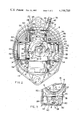
- FIG. 2 is a sectional view of the compressor as viewed along the axis of the crankshaft.
- FIG. 3 is a fragmentary sectional view along line 3--3 of FIG. 2 showing the tie rod and tubular rivet assembly.
- the compressor comprises a pair of cast aluminum crankcase halves or sections 6 and 8 with each of the sections 6 and 8 including semicylindrical recesses 10 therein.
- the semicylindrical recesses 10 are positioned with their axes running perpendicular to the axis of the crankshaft 12, and when the two crankcase sections 6 and 8 are assembled, the recesses 10 form the cylinders 14 within which the pistons 16 are received.
- the pistons 16 are part of a pair of integral, double-ended piston yoke elements 18. Pistons 16 are inserted within respective stamped steel cylinder liners 22, which are generally cylindrical in shape and include short flanges 24 on their distal ends. Also shown in FIG. 1 is one of the four valve plates 26 adapted to be seated on shoulders 24 in cylinder liners 22, and one of the discharge rivets 28. Due to the fact that the present invention is concerned with the crankcase and housing assembly, only the general outline of the compressor moving parts assembly is illustrated in FIG. 1.
- crankshaft 12 is rotatably received within bearing 30 and will be seen to include a lubricant passageway 32.
- Piston rings 34 are snap fit within grooves in pistons 16, and suction leaf valves 36 are connected to pistons 16 by means of rivets 38.
- Snap rings 40 retain valve plates 26 in place, and discharge leaf valves 42 are connected to valve plates 26 by valve retainers 43 and rivets 44. Cylinder liners 22 are held in place by means of their flanges 24 being clamped between shoulders on crankcase halves 6 and 8 and valve plates 26.
- crankcase sections 6 and 8 includes web portions 46 having flat mating surfaces 48 wich are in face-to-face abutment when the crankcase sections 6 and 8 are assembled. In order to ensure that there is no leakage between the high pressure chamber and lower pressure chamber, it is necessary that the facing surfaces 48 of web portions 46 make uniform, parallel contact.
- Crankcase sections 6 and 8 are connected together by means of tubular eyelet rivets 50, each of which includes an enlarged head portion 52. Each of the rivets extends through the openings 54 in crankcase sections 6 and 8 which are in alignment when the sections 6 and 8 are assembled, with the enlarged head portions 52 abutting raised areas 56 on the web portions of crankcase section 6.
- tubular rivets 50 are clinched so as to spread them out against the outer surface 58 of crankcase section 8 forming flange-like portions as illustrated in FIG. 3, such that the crankcase sections 6 and 8 are tightly secured together.
- Tubular rivets 50 also serve to seal the interface between the crankcase sections 6 and 8 in the area of openings 54 so that leakage between the high pressure and low pressure chambers is prevented.
- crankcase front housing section assembly comprising a front cover 60 and a rear cover 62, each of which is of stamped steel construction.
- the front cover 60 is somewhat larger than the rear cover 62 and abuts against the front face of crankcase section 6 with the tubular, crankshaft bearing portion 64 extending through an opening 66 in front cover 60.
- O-ring 68 seals the interface between front housing section 60 and crankcase section 6 in the area of opening 66, and nut 70 holds the crankcase front housing section assembly together.
- the rear housing section 62 abuts against crankcase section 8 and includes an axial intake chamber 72 which fits around the rearwardly facing tubular portion 74 of rear crankcase section 8.
- O-ring 76 which is compressed between rear housing section 62 and the rear surface of crankcase section 8, serves to seal the intake chamber 72 from the discharge chamber 94, the latter being formed between housing 60, 62 and crankcase 6, 8.
- Intake tube 78 communicates with the interior of chamber 72, and discharge tube 80 communicates with the interior of housing 60, 62.
- the housing halves 60 and 62 are held together by means of four steel tie rods 82, which are welded to the inner surface 84 of housing front section 60, extend through tubular rivets 50, and also extend through openings 86 in rear housing section 62 (FIG. 3). With the housing section 60 and 62 being held tightly together, welds 88 between tie rods 82 and the outer surface 90 of rear housing section 62 retain the assembly in place. Front and rear housing sections 60 and 62 are also welded together at 92 around the entire perimeter of their mutual interface. Although tie rods 82 have been shown as being welded in place, other fastening techniques, such as riveting, securing by means of nuts, etc. may be utilized as long as the interior of housing 60, 62 remains sealed.
- high pressure discharge chamber 94 is formed between housing 60, 62 and crankcase 6, 8, with the intake chamber 72 being sealed therefrom by means of O-ring 76.
- Tubular rivets 50 because they line openings 54 and are sealingly clinched tightly against crankcase halves 6 and 8, prevent leakage between the aforementioned high pressure and low pressure chambers 94 and 72 around openings 54.
- the piston-yoke elements 18 are preassembled with their rings 34 to cylinder liners 22, and this assembly is installed on the crankshaft. Then slide 20 is installed as a unit into crankcase section 6 followed by the second yoke/cylinder liner subassembly. The other half 8 of the crankcase is then placed over this assembly, tubular rivets 50 are inserted within openings 54 and their distal ends clinched against crankcase section 6 so as to hold the crankcase sections 6 and 8 tightly together, and the valve assemblies are installed.
- tie rods 82 are welded to the inner surface 84 of housing section 60, and the assembled crankcase including O-ring 68 is inserted within housing section 60 over tie rods 82, which are guided by means of tubular rivets 50. Nut 70 is then installed, which serves to retain the assembly in housing 60 and capture O-ring 68. After emplacing O-ring 76, the rear housing section 62 is placed over the assembled crankcase assembly and is inserted within front housing section 60 such that tie rods 82 extend through openings 86 (FIG. 3). The ends of tie rods 82 are then welded to the outer surface 90 of rear housing section 62, and the interface between housing sections 60 and 62 is sealed by means of weld 92.
- crankshaft 12 is rotated by means of a belt-pulley assembly (not shown)
- slide block 20 will cause pistons 16 to reciprocate within their respective cylinders 14 so as to draw gas into the cylinders 14 from intake chamber 72 and discharge the compressed gas into the discharge chamber 94.
- Incoming gas is brought into intake chamber 72 through intake tube 78, and the high pressure discharge gas is delivered to the refrigeration system condenser (not shown) through discharge tube 80.
Landscapes
- Engineering & Computer Science (AREA)
- Mechanical Engineering (AREA)
- General Engineering & Computer Science (AREA)
- Compressors, Vaccum Pumps And Other Relevant Systems (AREA)
- Compressor (AREA)
Priority Applications (14)
| Application Number | Priority Date | Filing Date | Title |
|---|---|---|---|
| US06/098,910 US4316705A (en) | 1979-11-30 | 1979-11-30 | Housing assembly for split crankcase radial compressor |
| CA000364158A CA1152045A (en) | 1979-11-30 | 1980-11-06 | Housing assembly for split crankcase radial compressor |
| AU64216/80A AU526958B2 (en) | 1979-11-30 | 1980-11-10 | Split crankcase radial compressor |
| GB8036542A GB2065240B (en) | 1979-11-30 | 1980-11-13 | Housing assembly for split crankcase radial compressor |
| DE3043121A DE3043121C2 (de) | 1979-11-30 | 1980-11-15 | Hermetisch abgedichteter Radialkolbenverdichter |
| IT8050263A IT1207157B (it) | 1979-11-30 | 1980-11-27 | Assieme di alloggiamento per compressore radiale a basamento diviso particolarmente adatto per l'impie go in condizionatori di aria per autoveicoli |
| BR8007761A BR8007761A (pt) | 1979-11-30 | 1980-11-27 | Compressor radial de carter dividido |
| ES497241A ES8202406A1 (es) | 1979-11-30 | 1980-11-28 | Perfeccionamientos en un compresor radial |
| IN1321/CAL/80A IN154147B (show.php) | 1979-11-30 | 1980-11-28 | |
| FR8025421A FR2471499B1 (fr) | 1979-11-30 | 1980-12-01 | Assemblage de logement pour compresseur radial a carter en deux parties |
| MX184973A MX155348A (es) | 1979-11-30 | 1980-12-01 | Mejoras en conjunto de alojamiento para compresor radial con caja de ciguenal dividida |
| JP55169463A JPS6050994B2 (ja) | 1979-11-30 | 1980-12-01 | ラジアルコンプレツサ |
| ES498647A ES498647A0 (es) | 1979-11-30 | 1981-01-20 | Un compresor perfeccionado |
| GB08314035A GB2129062B (en) | 1979-11-30 | 1983-05-20 | A compressor |
Applications Claiming Priority (1)
| Application Number | Priority Date | Filing Date | Title |
|---|---|---|---|
| US06/098,910 US4316705A (en) | 1979-11-30 | 1979-11-30 | Housing assembly for split crankcase radial compressor |
Publications (1)
| Publication Number | Publication Date |
|---|---|
| US4316705A true US4316705A (en) | 1982-02-23 |
Family
ID=22271509
Family Applications (1)
| Application Number | Title | Priority Date | Filing Date |
|---|---|---|---|
| US06/098,910 Expired - Lifetime US4316705A (en) | 1979-11-30 | 1979-11-30 | Housing assembly for split crankcase radial compressor |
Country Status (12)
| Country | Link |
|---|---|
| US (1) | US4316705A (show.php) |
| JP (1) | JPS6050994B2 (show.php) |
| AU (1) | AU526958B2 (show.php) |
| BR (1) | BR8007761A (show.php) |
| CA (1) | CA1152045A (show.php) |
| DE (1) | DE3043121C2 (show.php) |
| ES (2) | ES8202406A1 (show.php) |
| FR (1) | FR2471499B1 (show.php) |
| GB (2) | GB2065240B (show.php) |
| IN (1) | IN154147B (show.php) |
| IT (1) | IT1207157B (show.php) |
| MX (1) | MX155348A (show.php) |
Cited By (10)
| Publication number | Priority date | Publication date | Assignee | Title |
|---|---|---|---|---|
| DE3414463A1 (de) * | 1983-06-10 | 1984-12-13 | Tecumseh Products Co., Tecumseh, Mich. | Radialkompressor |
| US4829879A (en) * | 1986-05-05 | 1989-05-16 | Joe Santa & Associates Pty. Ltd. | Radial piston drive motor assembly with exhaust passages in cylinder |
| US4907950A (en) * | 1988-08-29 | 1990-03-13 | Pierrat Michel A | Variable positive fluid displacement system |
| US5288211A (en) * | 1992-07-08 | 1994-02-22 | Tecumseh Products Company | Internal baffle system for a multi-cylinder compressor |
| US5429080A (en) * | 1993-12-13 | 1995-07-04 | Evestar Technologies, Inc. | Compact internal combustion engine |
| US5980222A (en) * | 1997-11-13 | 1999-11-09 | Tecumseh Products Company | Hermetic reciprocating compressor having a housing divided into a low pressure portion and a high pressure portion |
| US6684755B2 (en) | 2002-01-28 | 2004-02-03 | Bristol Compressors, Inc. | Crankshaft, compressor using crankshaft, and method for assembling a compressor including installing crankshaft |
| US20070292282A1 (en) * | 2006-06-08 | 2007-12-20 | Schuetzle Larry A | Reciprocating compressor or pump and a portable tool powering system including a reciprocating compressor |
| US20150075369A1 (en) * | 2011-01-28 | 2015-03-19 | Wabtec Holding Corp. | Oil-free air compressor for rail vehicles with air ventilation |
| WO2017019758A1 (en) | 2015-07-27 | 2017-02-02 | Carleton Life Support Systems, Inc. | Sealed cavity compressor to reduce contaminant induction |
Families Citing this family (1)
| Publication number | Priority date | Publication date | Assignee | Title |
|---|---|---|---|---|
| DE102020109993A1 (de) | 2020-04-09 | 2021-10-14 | Thyssenkrupp Ag | Verdichter zum Verdichten von Kältemittel |
Citations (15)
| Publication number | Priority date | Publication date | Assignee | Title |
|---|---|---|---|---|
| US1820883A (en) * | 1929-07-31 | 1931-08-25 | Trico Products Corp | Pump |
| US2319718A (en) * | 1940-09-06 | 1943-05-18 | John W Brooks | Air compressor |
| US2586537A (en) * | 1948-06-17 | 1952-02-19 | Henry W Hapman | Conveyer sealing device |
| DE1096750B (de) * | 1956-10-27 | 1961-01-05 | Heilmeier & Weinlein | Kolbenpumpe mit sternfoermig angeordneten Zylinderbloecken |
| GB858595A (en) | 1958-04-08 | 1961-01-11 | Engineering Res & Applic Ltd | Improvements in or relating to internal combustion engines |
| GB876602A (en) | 1959-01-31 | 1961-09-06 | Culk Raimund | A co-axial cylinder-and-opposed-piston compressor suitable for refrigerators |
| US3246581A (en) * | 1963-10-23 | 1966-04-19 | Flo Tork Inc | Air actuator |
| US3431865A (en) * | 1966-04-21 | 1969-03-11 | Hypro Inc | Pump with concentric valve means |
| US3685923A (en) * | 1970-11-06 | 1972-08-22 | Gen Motors Corp | Automotive air conditioning compressor |
| US3838942A (en) * | 1971-07-30 | 1974-10-01 | Mitchell J Co | Refrigeration compressor |
| US3910164A (en) * | 1974-03-28 | 1975-10-07 | Gen Motors Corp | Split cylinder radial-four automotive air conditioning compressor |
| DE2415884A1 (de) * | 1974-04-02 | 1975-10-23 | Frieseke & Hoepfner Gmbh | Radialkolbenpumpe |
| US3924968A (en) * | 1972-07-27 | 1975-12-09 | Gen Motors Corp | Radial compressor with muffled gas chambers and short stable piston skirts and method of assembling same |
| US4050852A (en) * | 1976-09-13 | 1977-09-27 | General Motors Corporation | Variable displacement radial piston compressor |
| GB1565799A (en) | 1976-11-01 | 1980-04-23 | Wood J | Internal combustion engine body construction |
Family Cites Families (4)
| Publication number | Priority date | Publication date | Assignee | Title |
|---|---|---|---|---|
| GB225669A (en) * | 1923-10-13 | 1924-12-11 | Victaulic Company Ltd | Improvements in air receivers |
| GB499366A (en) * | 1938-07-15 | 1939-01-23 | Ambi Budd Presswerk Gmbh | A portable container for fluids under pressure |
| DE1296658B (de) * | 1961-11-28 | 1969-06-04 | Danfoss As | Motorverdichter fuer Kleinkaeltemaschinen |
| GB1019883A (show.php) * | 1962-11-15 | 1966-02-09 | Danfoss A/S |
-
1979
- 1979-11-30 US US06/098,910 patent/US4316705A/en not_active Expired - Lifetime
-
1980
- 1980-11-06 CA CA000364158A patent/CA1152045A/en not_active Expired
- 1980-11-10 AU AU64216/80A patent/AU526958B2/en not_active Ceased
- 1980-11-13 GB GB8036542A patent/GB2065240B/en not_active Expired
- 1980-11-15 DE DE3043121A patent/DE3043121C2/de not_active Expired
- 1980-11-27 IT IT8050263A patent/IT1207157B/it active
- 1980-11-27 BR BR8007761A patent/BR8007761A/pt unknown
- 1980-11-28 ES ES497241A patent/ES8202406A1/es not_active Expired
- 1980-11-28 IN IN1321/CAL/80A patent/IN154147B/en unknown
- 1980-12-01 FR FR8025421A patent/FR2471499B1/fr not_active Expired
- 1980-12-01 MX MX184973A patent/MX155348A/es unknown
- 1980-12-01 JP JP55169463A patent/JPS6050994B2/ja not_active Expired
-
1981
- 1981-01-20 ES ES498647A patent/ES498647A0/es active Granted
-
1983
- 1983-05-20 GB GB08314035A patent/GB2129062B/en not_active Expired
Patent Citations (15)
| Publication number | Priority date | Publication date | Assignee | Title |
|---|---|---|---|---|
| US1820883A (en) * | 1929-07-31 | 1931-08-25 | Trico Products Corp | Pump |
| US2319718A (en) * | 1940-09-06 | 1943-05-18 | John W Brooks | Air compressor |
| US2586537A (en) * | 1948-06-17 | 1952-02-19 | Henry W Hapman | Conveyer sealing device |
| DE1096750B (de) * | 1956-10-27 | 1961-01-05 | Heilmeier & Weinlein | Kolbenpumpe mit sternfoermig angeordneten Zylinderbloecken |
| GB858595A (en) | 1958-04-08 | 1961-01-11 | Engineering Res & Applic Ltd | Improvements in or relating to internal combustion engines |
| GB876602A (en) | 1959-01-31 | 1961-09-06 | Culk Raimund | A co-axial cylinder-and-opposed-piston compressor suitable for refrigerators |
| US3246581A (en) * | 1963-10-23 | 1966-04-19 | Flo Tork Inc | Air actuator |
| US3431865A (en) * | 1966-04-21 | 1969-03-11 | Hypro Inc | Pump with concentric valve means |
| US3685923A (en) * | 1970-11-06 | 1972-08-22 | Gen Motors Corp | Automotive air conditioning compressor |
| US3838942A (en) * | 1971-07-30 | 1974-10-01 | Mitchell J Co | Refrigeration compressor |
| US3924968A (en) * | 1972-07-27 | 1975-12-09 | Gen Motors Corp | Radial compressor with muffled gas chambers and short stable piston skirts and method of assembling same |
| US3910164A (en) * | 1974-03-28 | 1975-10-07 | Gen Motors Corp | Split cylinder radial-four automotive air conditioning compressor |
| DE2415884A1 (de) * | 1974-04-02 | 1975-10-23 | Frieseke & Hoepfner Gmbh | Radialkolbenpumpe |
| US4050852A (en) * | 1976-09-13 | 1977-09-27 | General Motors Corporation | Variable displacement radial piston compressor |
| GB1565799A (en) | 1976-11-01 | 1980-04-23 | Wood J | Internal combustion engine body construction |
Cited By (18)
| Publication number | Priority date | Publication date | Assignee | Title |
|---|---|---|---|---|
| DE3414463A1 (de) * | 1983-06-10 | 1984-12-13 | Tecumseh Products Co., Tecumseh, Mich. | Radialkompressor |
| US4829879A (en) * | 1986-05-05 | 1989-05-16 | Joe Santa & Associates Pty. Ltd. | Radial piston drive motor assembly with exhaust passages in cylinder |
| US4907950A (en) * | 1988-08-29 | 1990-03-13 | Pierrat Michel A | Variable positive fluid displacement system |
| US5288211A (en) * | 1992-07-08 | 1994-02-22 | Tecumseh Products Company | Internal baffle system for a multi-cylinder compressor |
| US5429080A (en) * | 1993-12-13 | 1995-07-04 | Evestar Technologies, Inc. | Compact internal combustion engine |
| US5980222A (en) * | 1997-11-13 | 1999-11-09 | Tecumseh Products Company | Hermetic reciprocating compressor having a housing divided into a low pressure portion and a high pressure portion |
| US6155805A (en) * | 1997-11-13 | 2000-12-05 | Tecumseh Products Company | Hermetic compressor having acoustic insulator |
| US6684755B2 (en) | 2002-01-28 | 2004-02-03 | Bristol Compressors, Inc. | Crankshaft, compressor using crankshaft, and method for assembling a compressor including installing crankshaft |
| US20070292282A1 (en) * | 2006-06-08 | 2007-12-20 | Schuetzle Larry A | Reciprocating compressor or pump and a portable tool powering system including a reciprocating compressor |
| US20080003112A1 (en) * | 2006-06-08 | 2008-01-03 | Schuetzle Larry A | Reciprocating compressor or pump and a portable tool powering system including a reciprocating compressor |
| US7959415B2 (en) * | 2006-06-08 | 2011-06-14 | Larry Alvin Schuetzle | Radial type reciprocating compressor and portable tool powering system with cylinder liner, valve and annular manifold arrangement |
| US8721300B2 (en) | 2006-06-08 | 2014-05-13 | Larry Alvin Schuetzle | Reciprocating compressor or pump and a portable tool powering system including a reciprocating compressor |
| US20150075369A1 (en) * | 2011-01-28 | 2015-03-19 | Wabtec Holding Corp. | Oil-free air compressor for rail vehicles with air ventilation |
| US9856866B2 (en) | 2011-01-28 | 2018-01-02 | Wabtec Holding Corp. | Oil-free air compressor for rail vehicles |
| WO2017019758A1 (en) | 2015-07-27 | 2017-02-02 | Carleton Life Support Systems, Inc. | Sealed cavity compressor to reduce contaminant induction |
| US20170030346A1 (en) * | 2015-07-27 | 2017-02-02 | Carleton Life Support Systems Inc. | Sealed cavity compressor to reduce contaminant induction |
| EP3329122A4 (en) * | 2015-07-27 | 2018-12-26 | Carleton Life Support Systems, Inc. | Sealed cavity compressor to reduce contaminant induction |
| US11002268B2 (en) * | 2015-07-27 | 2021-05-11 | Cobham Mission Systems Davenport Lss Inc. | Sealed cavity compressor to reduce contaminant induction |
Also Published As
| Publication number | Publication date |
|---|---|
| DE3043121A1 (de) | 1981-06-25 |
| ES497241A0 (es) | 1982-01-16 |
| GB2129062A (en) | 1984-05-10 |
| IN154147B (show.php) | 1984-09-29 |
| ES8204078A1 (es) | 1982-04-01 |
| GB2065240A (en) | 1981-06-24 |
| FR2471499B1 (fr) | 1985-08-30 |
| GB8314035D0 (en) | 1983-06-29 |
| DE3043121C2 (de) | 1985-07-04 |
| BR8007761A (pt) | 1981-06-09 |
| IT1207157B (it) | 1989-05-17 |
| IT8050263A0 (it) | 1980-11-27 |
| ES498647A0 (es) | 1982-04-01 |
| CA1152045A (en) | 1983-08-16 |
| JPS5696186A (en) | 1981-08-04 |
| ES8202406A1 (es) | 1982-01-16 |
| FR2471499A1 (fr) | 1981-06-19 |
| JPS6050994B2 (ja) | 1985-11-11 |
| GB2129062B (en) | 1984-10-10 |
| MX155348A (es) | 1988-02-22 |
| AU526958B2 (en) | 1983-02-10 |
| GB2065240B (en) | 1984-06-20 |
Similar Documents
| Publication | Publication Date | Title |
|---|---|---|
| US4316705A (en) | Housing assembly for split crankcase radial compressor | |
| CA2547040C (en) | Pump improvements | |
| US5326231A (en) | Gas compressor construction and assembly | |
| AU601890B2 (en) | Compressor valve system | |
| US5100306A (en) | Noise reducing compressor gasket and head assembly | |
| CA2948495C (en) | Radially configured oil-free compressor | |
| US4547131A (en) | Refrigeration compressor and method of assembling same | |
| EP0325695B1 (en) | Compressor discharge muffler having cover plate | |
| US20040202562A1 (en) | Reciprocating compressor | |
| KR100189577B1 (ko) | 왕복운동형 압축기 | |
| US4474541A (en) | Internal crankcase support for a radial compressor | |
| US3910164A (en) | Split cylinder radial-four automotive air conditioning compressor | |
| JP2769340B2 (ja) | エアーコンディショニング用コンプレッサー | |
| US4101250A (en) | Swash plate type compressor | |
| US4273519A (en) | Split crankcase radial automotive compressor | |
| US5387092A (en) | A/C compressor with integrally molded housings | |
| US20050249608A1 (en) | Inclined plate-type compressors and air conditioning systems including such compressors | |
| US5232354A (en) | Compressor discharge valve assembly having plural wave ring biasing means | |
| US4717313A (en) | Swash plate type compressor with internal sealing | |
| US4358251A (en) | Split crankcase radial automotive compressor | |
| GB2179709A (en) | Hermetic refrigeration compressor | |
| CA1119138A (en) | Split crankcase radial automotive compressor | |
| CN210106172U (zh) | 旋转式压缩机及其压缩机构和制冷装置 | |
| JPS5916545Y2 (ja) | 流体圧縮機 |
Legal Events
| Date | Code | Title | Description |
|---|---|---|---|
| STCF | Information on status: patent grant |
Free format text: PATENTED CASE |