US4309587A - Horizontal electro-slag welding process for surfacing - Google Patents
Horizontal electro-slag welding process for surfacing Download PDFInfo
- Publication number
- US4309587A US4309587A US06/122,875 US12287580A US4309587A US 4309587 A US4309587 A US 4309587A US 12287580 A US12287580 A US 12287580A US 4309587 A US4309587 A US 4309587A
- Authority
- US
- United States
- Prior art keywords
- strip electrode
- slag
- molten
- electrode
- surfacing
- Prior art date
- Legal status (The legal status is an assumption and is not a legal conclusion. Google has not performed a legal analysis and makes no representation as to the accuracy of the status listed.)
- Expired - Lifetime
Links
Images


Classifications
-
- B—PERFORMING OPERATIONS; TRANSPORTING
- B23—MACHINE TOOLS; METAL-WORKING NOT OTHERWISE PROVIDED FOR
- B23K—SOLDERING OR UNSOLDERING; WELDING; CLADDING OR PLATING BY SOLDERING OR WELDING; CUTTING BY APPLYING HEAT LOCALLY, e.g. FLAME CUTTING; WORKING BY LASER BEAM
- B23K9/00—Arc welding or cutting
- B23K9/04—Welding for other purposes than joining, e.g. built-up welding
-
- B—PERFORMING OPERATIONS; TRANSPORTING
- B23—MACHINE TOOLS; METAL-WORKING NOT OTHERWISE PROVIDED FOR
- B23K—SOLDERING OR UNSOLDERING; WELDING; CLADDING OR PLATING BY SOLDERING OR WELDING; CUTTING BY APPLYING HEAT LOCALLY, e.g. FLAME CUTTING; WORKING BY LASER BEAM
- B23K25/00—Slag welding, i.e. using a heated layer or mass of powder, slag, or the like in contact with the material to be joined
- B23K25/005—Welding for purposes other than joining, e.g. built-up welding
Definitions
- the present invention relates to horizontal electro-slag welding process for surfacing and particularly an improvement of an over-lay welding process for obtaining a flat surface at the overlap area adjacent two weld passes.
- FIG. 1 is a view for explaining the cause of forming undercuts.
- FIG. 1 (a) shows the case where the current distributes uniformly in the width direction of a strip electrode 1 and FIG. 1, (b) shows the case where the current shifts and flows to one side of the strip electrode 1.
- molten metal and slag flow mainly toward one direction as shown by a white arrow ⁇ ' and an undercut is formed at one side e' of the molten pool 2.
- a numeral 2' is a base metal and a letter f is a magnetic flux.
- FIG. 1, (a) and (d) are schematic views for explaining the cause for undercuts formed at the overlapped area of the welded beads;
- FIG. 2 is a schematic view showing an example when an austenite stainless steel electrode is used in the electro-slag welding process
- FIG. 3, (a)-(f) are views for explaining the slag flow patterns against the coil current
- FIG. 4 is a schematic view when another example is carried out by using another coil
- FIG. 5, (a)-(f) are views for showing the relation of the slag flows to the coil currents
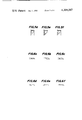
- FIG. 6, (a)-(f) are views showing the cross-sections of the beads
- FIG. 7 is a schematic view showing an example when a ferrite electrode is used.
- FIG. 8 is a schematic view showing an example when independent coils are used.
- Over-lay weldings were conducted by using a strip electrode 1 having a width of 150 mm, arranging a coil wound around an iron core in 250 turns at the position as shown in FIG. 2 and passing the various currents as shown in Table 1 through the coil to form two beads, which were overlapped over a width of 8-10 mm, in parallel.
- the flowing directions of the molten slag are shown in FIG. 3 and the number of the formed undercut is shown in the following Table 1.
- Coil current -5 means that the current is passed in the reverse direction to the direction in FIG. 2.
- Over-lay welding was conducted by using a strip electrode having a width of 75 mm and arranging a coil 3' wound around an iron core in 460 turns as shown in FIG. 4, and varying the coil current as disclosed in the following Table 2.
- Table 2 Table 2
- Undercuts are formed locally at both edges of the bead. While, when 0.5 A of coil current is passed, molten metal and slag in the vicinity of the strip electrode flow toward the already formed bead, whereby the formation of the undercut can be prevented. The satisfactory bead is obtained until 2 A.
- an austenite strip electrode was used and in order to prevent the burning damage of the coils 3 and 3' due to heat irradiation of the molten pool 2, the coils 3 and 3' were arranged in front of the strip electrode 1, but when a ferrite strip electrode is used in such a coil arrangement, it is impossible to apply effectively the magnetic field to the molten pool due to magnetic shield by the ferrite strip. In this case, it is effective to apply the magnetic field from a position just above the molten pool 2 behind the strip electrode 1 by means of a coil 3" composed of an elongated core shown in FIG. 7. Furthermore, even when a strip austenite electrode is used, it is permissible to arrange the above described coil 3" above the molten pool 2.
- the reverse polarity (electrode +, base plate -) was used.
- the magnetic field should be applied in the contrary directions to those shown in FIGS. 2, 4, 7 and 8 to flow the molten pool in the same direction as in the reverse polarity.
- a single coil is used but the more preferable result can be obtained by arranging plural coils in series and energizing these coils by the same current, or more preferably by plural coils independently as shown in FIG. 8 respectively.
- the undercuts at the overlapped area adjacent two beads which prevail the major part of defects in the horizontal electroslag welding for surfacing, can be completely prevented by arranging a very simple coil on a usual welding machine.
Landscapes
- Engineering & Computer Science (AREA)
- Mechanical Engineering (AREA)
- Physics & Mathematics (AREA)
- Plasma & Fusion (AREA)
- Arc Welding Control (AREA)
- Butt Welding And Welding Of Specific Article (AREA)
- Arc Welding In General (AREA)
Applications Claiming Priority (2)
| Application Number | Priority Date | Filing Date | Title |
|---|---|---|---|
| JP54044178A JPS5811317B2 (ja) | 1979-04-13 | 1979-04-13 | 水平エレクトロスラグ肉盛り溶接法 |
| JP54-44178 | 1979-04-13 |
Publications (1)
| Publication Number | Publication Date |
|---|---|
| US4309587A true US4309587A (en) | 1982-01-05 |
Family
ID=12684317
Family Applications (1)
| Application Number | Title | Priority Date | Filing Date |
|---|---|---|---|
| US06/122,875 Expired - Lifetime US4309587A (en) | 1979-04-13 | 1980-02-20 | Horizontal electro-slag welding process for surfacing |
Country Status (8)
| Country | Link |
|---|---|
| US (1) | US4309587A (de) |
| JP (1) | JPS5811317B2 (de) |
| BR (1) | BR8002215A (de) |
| CA (1) | CA1154100A (de) |
| DE (1) | DE3009967C2 (de) |
| ES (1) | ES489703A0 (de) |
| FR (1) | FR2453704A1 (de) |
| GB (1) | GB2047595B (de) |
Cited By (12)
| Publication number | Priority date | Publication date | Assignee | Title |
|---|---|---|---|---|
| US5068507A (en) * | 1987-12-03 | 1991-11-26 | Commonwealth Scientific And Industrial Research Organisation | Electroslag surfacing |
| US5458754A (en) | 1991-04-22 | 1995-10-17 | Multi-Arc Scientific Coatings | Plasma enhancement apparatus and method for physical vapor deposition |
| US5942289A (en) * | 1997-03-26 | 1999-08-24 | Amorphous Technologies International | Hardfacing a surface utilizing a method and apparatus having a chill block |
| US20060124209A1 (en) * | 2002-12-20 | 2006-06-15 | Jan Schroers | Pt-base bulk solidifying amorphous alloys |
| US20060157164A1 (en) * | 2002-12-20 | 2006-07-20 | William Johnson | Bulk solidifying amorphous alloys with improved mechanical properties |
| US20100065337A1 (en) * | 2008-09-18 | 2010-03-18 | Baker Hughes Incorporated | Method and Apparatus for the Automated Application of Hardfacing Material to Rolling Cutters of Earth-Boring Drill Bits |
| US20100104736A1 (en) * | 2008-10-23 | 2010-04-29 | Baker Hughes Incorporated | Method and apparatus for automated application of hardfacing material to drill bits |
| US20100106285A1 (en) * | 2008-10-29 | 2010-04-29 | Massey Alan J | Method and apparatus for robotic welding of drill bits |
| US20100159157A1 (en) * | 2008-10-23 | 2010-06-24 | Stevens John H | Robotically applied hardfacing with pre-heat |
| US20110186183A1 (en) * | 2002-12-20 | 2011-08-04 | William Johnson | Bulk solidifying amorphous alloys with improved mechanical properties |
| US20160175984A1 (en) * | 2014-12-17 | 2016-06-23 | Airbus Group Limited | Method and Apparatus for Distortion Control on Additively Manufactured Parts Using Wire Feed and Magnetic Pulses |
| US11371108B2 (en) | 2019-02-14 | 2022-06-28 | Glassimetal Technology, Inc. | Tough iron-based glasses with high glass forming ability and high thermal stability |
Families Citing this family (2)
| Publication number | Priority date | Publication date | Assignee | Title |
|---|---|---|---|---|
| JPS5827035B2 (ja) * | 1979-09-14 | 1983-06-07 | 株式会社神戸製鋼所 | 帯状電極による肉盛溶接方法 |
| JPS57168778A (en) * | 1981-04-08 | 1982-10-18 | Kawasaki Steel Corp | Controlling method for welding using belt-like electrode |
Citations (4)
| Publication number | Priority date | Publication date | Assignee | Title |
|---|---|---|---|---|
| US3584181A (en) * | 1968-05-31 | 1971-06-08 | Hitachi Ltd | Method of arc welding for hard facing |
| US3882298A (en) * | 1972-04-14 | 1975-05-06 | Boehler & Co Ag Geb | Method of and apparatus for the submerged arc surfacing of metallic work pieces |
| US4027135A (en) * | 1975-07-17 | 1977-05-31 | Combustion Engineering, Inc. | Apparatus and method for submerged arc strip cladding of metallic work pieces |
| US4190760A (en) * | 1976-05-14 | 1980-02-26 | Kobe Steel, Ltd. | Welding apparatus with shifting magnetic field |
Family Cites Families (5)
| Publication number | Priority date | Publication date | Assignee | Title |
|---|---|---|---|---|
| CH508735A (de) * | 1969-01-29 | 1971-06-15 | Sulzer Ag | Vorrichtung zum Plattieren von metallischen Werkstücken mit Hilfe eines elektrischen Lichtbogens |
| DE2218078B2 (de) * | 1972-04-14 | 1974-08-15 | Gebr. Boehler & Co Ag, Wien | Verfahren und Einrichtung zur Auftragschweißung |
| JPS5017349A (de) * | 1973-06-19 | 1975-02-24 | ||
| JPS5286949A (en) * | 1976-01-14 | 1977-07-20 | Matsushita Electric Ind Co Ltd | Brazing method of aluminium hot plate |
| JPS5286945A (en) * | 1976-05-20 | 1977-07-20 | Kobe Steel Ltd | Banddlike electrode arc welding equipment |
-
1979
- 1979-04-13 JP JP54044178A patent/JPS5811317B2/ja not_active Expired
-
1980
- 1980-02-18 CA CA000345850A patent/CA1154100A/en not_active Expired
- 1980-02-20 US US06/122,875 patent/US4309587A/en not_active Expired - Lifetime
- 1980-03-13 FR FR8005643A patent/FR2453704A1/fr active Granted
- 1980-03-14 DE DE3009967A patent/DE3009967C2/de not_active Expired
- 1980-03-18 ES ES489703A patent/ES489703A0/es active Granted
- 1980-03-24 GB GB8009818A patent/GB2047595B/en not_active Expired
- 1980-04-10 BR BR8002215A patent/BR8002215A/pt not_active IP Right Cessation
Patent Citations (4)
| Publication number | Priority date | Publication date | Assignee | Title |
|---|---|---|---|---|
| US3584181A (en) * | 1968-05-31 | 1971-06-08 | Hitachi Ltd | Method of arc welding for hard facing |
| US3882298A (en) * | 1972-04-14 | 1975-05-06 | Boehler & Co Ag Geb | Method of and apparatus for the submerged arc surfacing of metallic work pieces |
| US4027135A (en) * | 1975-07-17 | 1977-05-31 | Combustion Engineering, Inc. | Apparatus and method for submerged arc strip cladding of metallic work pieces |
| US4190760A (en) * | 1976-05-14 | 1980-02-26 | Kobe Steel, Ltd. | Welding apparatus with shifting magnetic field |
Cited By (25)
| Publication number | Priority date | Publication date | Assignee | Title |
|---|---|---|---|---|
| US5068507A (en) * | 1987-12-03 | 1991-11-26 | Commonwealth Scientific And Industrial Research Organisation | Electroslag surfacing |
| US5458754A (en) | 1991-04-22 | 1995-10-17 | Multi-Arc Scientific Coatings | Plasma enhancement apparatus and method for physical vapor deposition |
| US6139964A (en) | 1991-04-22 | 2000-10-31 | Multi-Arc Inc. | Plasma enhancement apparatus and method for physical vapor deposition |
| US5942289A (en) * | 1997-03-26 | 1999-08-24 | Amorphous Technologies International | Hardfacing a surface utilizing a method and apparatus having a chill block |
| US20110186183A1 (en) * | 2002-12-20 | 2011-08-04 | William Johnson | Bulk solidifying amorphous alloys with improved mechanical properties |
| US7582172B2 (en) | 2002-12-20 | 2009-09-01 | Jan Schroers | Pt-base bulk solidifying amorphous alloys |
| US9745651B2 (en) | 2002-12-20 | 2017-08-29 | Crucible Intellectual Property, Llc | Bulk solidifying amorphous alloys with improved mechanical properties |
| US8882940B2 (en) | 2002-12-20 | 2014-11-11 | Crucible Intellectual Property, Llc | Bulk solidifying amorphous alloys with improved mechanical properties |
| US20060157164A1 (en) * | 2002-12-20 | 2006-07-20 | William Johnson | Bulk solidifying amorphous alloys with improved mechanical properties |
| US7896982B2 (en) | 2002-12-20 | 2011-03-01 | Crucible Intellectual Property, Llc | Bulk solidifying amorphous alloys with improved mechanical properties |
| US20060124209A1 (en) * | 2002-12-20 | 2006-06-15 | Jan Schroers | Pt-base bulk solidifying amorphous alloys |
| US8828155B2 (en) | 2002-12-20 | 2014-09-09 | Crucible Intellectual Property, Llc | Bulk solidifying amorphous alloys with improved mechanical properties |
| US8698038B2 (en) | 2008-09-18 | 2014-04-15 | Baker Hughes Incorporated | Method and apparatus for the automated application of hardfacing material to rolling cutters of earth-boring drill bits |
| US20100065337A1 (en) * | 2008-09-18 | 2010-03-18 | Baker Hughes Incorporated | Method and Apparatus for the Automated Application of Hardfacing Material to Rolling Cutters of Earth-Boring Drill Bits |
| US20100159157A1 (en) * | 2008-10-23 | 2010-06-24 | Stevens John H | Robotically applied hardfacing with pre-heat |
| US8450637B2 (en) | 2008-10-23 | 2013-05-28 | Baker Hughes Incorporated | Apparatus for automated application of hardfacing material to drill bits |
| US8969754B2 (en) | 2008-10-23 | 2015-03-03 | Baker Hughes Incorporated | Methods for automated application of hardfacing material to drill bits |
| US9439277B2 (en) | 2008-10-23 | 2016-09-06 | Baker Hughes Incorporated | Robotically applied hardfacing with pre-heat |
| US9580788B2 (en) | 2008-10-23 | 2017-02-28 | Baker Hughes Incorporated | Methods for automated deposition of hardfacing material on earth-boring tools and related systems |
| US20100104736A1 (en) * | 2008-10-23 | 2010-04-29 | Baker Hughes Incorporated | Method and apparatus for automated application of hardfacing material to drill bits |
| US20100106285A1 (en) * | 2008-10-29 | 2010-04-29 | Massey Alan J | Method and apparatus for robotic welding of drill bits |
| US8948917B2 (en) | 2008-10-29 | 2015-02-03 | Baker Hughes Incorporated | Systems and methods for robotic welding of drill bits |
| US20160175984A1 (en) * | 2014-12-17 | 2016-06-23 | Airbus Group Limited | Method and Apparatus for Distortion Control on Additively Manufactured Parts Using Wire Feed and Magnetic Pulses |
| US10987755B2 (en) * | 2014-12-17 | 2021-04-27 | Airbus Defence and Space GmbH | Method and apparatus for distortion control on additively manufactured parts using wire feed and magnetic pulses |
| US11371108B2 (en) | 2019-02-14 | 2022-06-28 | Glassimetal Technology, Inc. | Tough iron-based glasses with high glass forming ability and high thermal stability |
Also Published As
| Publication number | Publication date |
|---|---|
| GB2047595A (en) | 1980-12-03 |
| DE3009967C2 (de) | 1983-11-24 |
| CA1154100A (en) | 1983-09-20 |
| JPS55136566A (en) | 1980-10-24 |
| ES8101436A1 (es) | 1980-12-16 |
| FR2453704B1 (de) | 1985-03-08 |
| DE3009967A1 (de) | 1980-10-16 |
| JPS5811317B2 (ja) | 1983-03-02 |
| ES489703A0 (es) | 1980-12-16 |
| BR8002215A (pt) | 1980-11-25 |
| FR2453704A1 (fr) | 1980-11-07 |
| GB2047595B (en) | 1982-11-10 |
Similar Documents
| Publication | Publication Date | Title |
|---|---|---|
| US4309587A (en) | Horizontal electro-slag welding process for surfacing | |
| EP0844039B1 (de) | Verfahren zum horizontalschweissen und schweissvorrichtung | |
| JP3530322B2 (ja) | 上向・立向溶接方法 | |
| US4190760A (en) | Welding apparatus with shifting magnetic field | |
| US4795872A (en) | Electromagnetic induction heating apparatus including a magnetic flux diverting assembly | |
| US4027135A (en) | Apparatus and method for submerged arc strip cladding of metallic work pieces | |
| JP2008055446A (ja) | 電磁力を用いた溶接方法及び溶接装置 | |
| KR100231369B1 (ko) | 연장된 형태의 야금소재의 통로중에서의 유도가열 방법 및 장치 | |
| US4020314A (en) | Delivery of welding flux in a method of submerged arc strip cladding of metallic work pieces | |
| US4511784A (en) | Method for welding by magnetically driven arc | |
| DE1615161C3 (de) | Elektrode und Verfahren zum Schweißen mit elektromagnetisch gerichtetem Lichtbogen | |
| US3882298A (en) | Method of and apparatus for the submerged arc surfacing of metallic work pieces | |
| US1947077A (en) | Arc welding | |
| US2001179A (en) | Electric arc welding | |
| EP0076324A1 (de) | Verfahren zum Steuern des Schweissens mit Bandelektrode | |
| JP2001205435A (ja) | 狭開先用磁気制御溶接方法及びその装置 | |
| US2680798A (en) | Method of high current density arc welding | |
| US1826355A (en) | Arc-welding | |
| JPS6238768A (ja) | 横向tigア−ク溶接方法 | |
| US1840330A (en) | Apparatus for electric arc welding pipe | |
| US5021669A (en) | Process and system for the control of the focusing of a beam of monopolar charged particles | |
| CS210648B2 (en) | Method of metallic workpiece flux surfacing and apparatus for making the same | |
| JP2570924B2 (ja) | 連続通板する鋼板の振動および板反り防止方法 | |
| DD268418A1 (de) | Elektromagnetische spannvorrichtung fuer das stumpfstossschweissen ebener bleche | |
| JPS6335352B2 (de) |
Legal Events
| Date | Code | Title | Description |
|---|---|---|---|
| STCF | Information on status: patent grant |
Free format text: PATENTED CASE |