US4306689A - Device for suppressing deviations in the output voltage of a pressure transducer in magnetic tape recorders caused by temperature fluctuations - Google Patents
Device for suppressing deviations in the output voltage of a pressure transducer in magnetic tape recorders caused by temperature fluctuations Download PDFInfo
- Publication number
- US4306689A US4306689A US06/123,985 US12398580A US4306689A US 4306689 A US4306689 A US 4306689A US 12398580 A US12398580 A US 12398580A US 4306689 A US4306689 A US 4306689A
- Authority
- US
- United States
- Prior art keywords
- pressure transducer
- temperature
- amplifier
- output
- voltage
- Prior art date
- Legal status (The legal status is an assumption and is not a legal conclusion. Google has not performed a legal analysis and makes no representation as to the accuracy of the status listed.)
- Expired - Lifetime
Links
Images
Classifications
-
- G—PHYSICS
- G11—INFORMATION STORAGE
- G11B—INFORMATION STORAGE BASED ON RELATIVE MOVEMENT BETWEEN RECORD CARRIER AND TRANSDUCER
- G11B15/00—Driving, starting or stopping record carriers of filamentary or web form; Driving both such record carriers and heads; Guiding such record carriers or containers therefor; Control thereof; Control of operating function
- G11B15/56—Driving, starting or stopping record carriers of filamentary or web form; Driving both such record carriers and heads; Guiding such record carriers or containers therefor; Control thereof; Control of operating function the record carrier having reserve loop, e.g. to minimise inertia during acceleration measuring or control in connection therewith
- G11B15/58—Driving, starting or stopping record carriers of filamentary or web form; Driving both such record carriers and heads; Guiding such record carriers or containers therefor; Control thereof; Control of operating function the record carrier having reserve loop, e.g. to minimise inertia during acceleration measuring or control in connection therewith with vacuum column
-
- G—PHYSICS
- G01—MEASURING; TESTING
- G01L—MEASURING FORCE, STRESS, TORQUE, WORK, MECHANICAL POWER, MECHANICAL EFFICIENCY, OR FLUID PRESSURE
- G01L9/00—Measuring steady of quasi-steady pressure of fluid or fluent solid material by electric or magnetic pressure-sensitive elements; Transmitting or indicating the displacement of mechanical pressure-sensitive elements, used to measure the steady or quasi-steady pressure of a fluid or fluent solid material, by electric or magnetic means
- G01L9/02—Measuring steady of quasi-steady pressure of fluid or fluent solid material by electric or magnetic pressure-sensitive elements; Transmitting or indicating the displacement of mechanical pressure-sensitive elements, used to measure the steady or quasi-steady pressure of a fluid or fluent solid material, by electric or magnetic means by making use of variations in ohmic resistance, e.g. of potentiometers, electric circuits therefor, e.g. bridges, amplifiers or signal conditioning
- G01L9/025—Measuring steady of quasi-steady pressure of fluid or fluent solid material by electric or magnetic pressure-sensitive elements; Transmitting or indicating the displacement of mechanical pressure-sensitive elements, used to measure the steady or quasi-steady pressure of a fluid or fluent solid material, by electric or magnetic means by making use of variations in ohmic resistance, e.g. of potentiometers, electric circuits therefor, e.g. bridges, amplifiers or signal conditioning with temperature compensating means
Definitions
- the invention relates to a device for disabling or suppressing deviations in the output voltage of a pressure transducer upon measurement of the pressure in the buffer chamber of magnetic tape recorders functioning with an analog control, said deviations of the output voltage being caused by temperature changes.
- magnetic tape recorders for data processing systems employ so-called buffer chambers in which a part of the magnetic tape is intermediately stored. This is shown in FIG. 6, for example, of "Elektronische Rechenanlagen", 4 month, 1968, pages 181-186, incorporated herein by reference.
- buffer chambers in which a part of the magnetic tape is intermediately stored.
- FIG. 6 shows in which a part of the magnetic tape is intermediately stored.
- FIG. 6 for example, of "Elektronische Rechenanlagen", 4 month, 1968, pages 181-186, incorporated herein by reference.
- analog control in which, for example, with the assistance of a pressure transducer, the pressure prevailing in a specific part of the buffer chamber, and dependent on the position of the tape loop in the buffer chamber, is measured and converted into an electrical magnitude, for example, a voltage.
- the output voltage of such a pressure transducer depends on the pressure at its input, but, on the other hand, also depends on the prevailing ambient temperature. Accordingly, the case often occurs that different units of one and the same type of pressure transducer exhibit a temperature coefficient of varying size and, in addition thereto, a positive or negative temperature coefficient.
- An object of the present invention is therefore to create a device for compensating deviations of the output voltage of a pressure transducer caused by temperature changes in which one need not take into consideration whether the pressure transducer employed exhibits a great or small or positive or negative temperature coefficient, respectively.
- a device for generating a voltage dependent on the temperature of the pressure transducer by means of a differential amplifier with a potentiometer connected between its two inputs, the temperature-dependent voltage pending at the adjustable tap of said potentiometer, and by means of an operational amplifier whose input is connected, on the one hand, to the output of the differential amplifier and, on the other hand, to the output of the pressure transducer.
- the device of the invention has the advantage that, given the structure of magnetic tape devices with analog control in which pressure transducers of the aforementioned type are employed, no expensive determination of the temperature coefficients of the output voltage of the pressure transducer employed is now required. Further, the individual dimensioning of compensation means is simplified in that the steepness and the direction of the compensation voltage for the output voltage of the pressure transducer can be set with a single potentiometer.
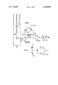
- FIG. 1 is a schematic illustration of the temperature control system of the invention for a magnetic tape device having a vacuum buffer chamber
- FIG. 2 is a schematic diagram of a preferred embodiment for a temperature/voltage converter device shown in FIG. 1.
- FIG. 1 shows a part of a vacuum buffer chamber 1 of a magnetic tape device in which a tape loop 2 is situated.
- a space or region 10 (mixing chamber) provided with small bores 14 leading to the buffer chamber is situated in a known manner in the back wall of the buffer chamber 1, the hose line 13 of a pressure transducer 3 opening into said space 10 in order to measure the pressure in the mixing chamber 10.
- this pressure depends on the position of the tape loop 2 in the buffer chamber as shown in FIG. 1 such that more or less of the bore holes 14 of chamber 10 are subject to the pressure in the buffer chamber below the tape loop 2.
- the inventive device has a temperature/voltage converter chamber 10 are subject to the pressure in the buffer chamber below the tape loop 2 device 4 which generates a voltage dependent on the temperature of the pressure transducer 3. This voltage is supplied to the adjustable tap of a potentiometer 5 which is connected between the two inputs of a differential amplifier 6. The output of the differential amplifier 6, together with the output of the pressure transducer 3, is connected to the input of an operational amplifier 7 whose output signal controls the tape heel winding motor 9 for controlling the tape loop 2 in the vacuum buffer chamber 1 via a final amplifier 8.
- FIG. 2 shows a particularly advantageous embodiment for the device 4.
- This consists of a thermistor 12 arranged on the pressure transducer 3.
- This thermistor 12 is electrically connected in series with a fixed resistor 11 between fixed voltages +U, -U, and at a junction A with the fixed resistor 11, the temperature-dependent voltage is tapped.
- the device illustrated in FIG. 1 and particularly executed in the form of FIG. 2 functions as follows.
- the voltage divider consisting of the thermistor 12 and the fixed resistor 11 is preferably dimensioned such that, given normal temperature at point A, a potential of zero volts prevails. In this state, the output voltage of the operational amplifier 7 is measured.
- the value measured at the output of the operational amplifier 7 is reset with the potentiometer 5 to the value measured given normal temperature.
- the height of the temperature in the admissible working range of the pressure transducer at which this re-adjustment ensues is without significance since both the output voltage of the pressure transducer as well as the resistance of the thermistor 12 change linearly with the temperature in this range. With the change of the adjustment of the potentiometer 5, thus two straight lines are brought into coincidence and it is therefore of no significance at which temperature this ensues. That which is essentially novel and the great advance of the subject matter of the application is to be seen in the particularly simple, universal adjustment possibility for the compensation voltage.
Landscapes
- Physics & Mathematics (AREA)
- General Physics & Mathematics (AREA)
- Measuring Fluid Pressure (AREA)
- Measuring Magnetic Variables (AREA)
Applications Claiming Priority (2)
| Application Number | Priority Date | Filing Date | Title |
|---|---|---|---|
| DE2914037 | 1979-04-06 | ||
| DE2914037A DE2914037C2 (de) | 1979-04-06 | 1979-04-06 | Einrichtung zum Unwirksammachen von durch Temperaturschwankungen verursachten Abweichungen der Ausgangsspannung eines Druckwandlers in Magnetbandgeräten |
Publications (1)
| Publication Number | Publication Date |
|---|---|
| US4306689A true US4306689A (en) | 1981-12-22 |
Family
ID=6067703
Family Applications (1)
| Application Number | Title | Priority Date | Filing Date |
|---|---|---|---|
| US06/123,985 Expired - Lifetime US4306689A (en) | 1979-04-06 | 1980-02-25 | Device for suppressing deviations in the output voltage of a pressure transducer in magnetic tape recorders caused by temperature fluctuations |
Country Status (4)
| Country | Link |
|---|---|
| US (1) | US4306689A (de) |
| EP (1) | EP0016866B1 (de) |
| AT (1) | ATE1122T1 (de) |
| DE (1) | DE2914037C2 (de) |
Families Citing this family (4)
| Publication number | Priority date | Publication date | Assignee | Title |
|---|---|---|---|---|
| DE3431517C2 (de) * | 1984-08-28 | 1986-09-04 | Kernforschungsanlage Jülich GmbH, 5170 Jülich | Verfahren zur Druckmessung mit einem Gasreibungsvakuummeter und Gasreibungsvakuummeter zur Durchführung des Verfahrens |
| US5228635A (en) * | 1990-01-26 | 1993-07-20 | Sony Corporation | Apparatus having a vacuum chamber for controlling a tape tension thereof/vacuum chamber apparatus for controlling tape tension |
| JP3187819B2 (ja) * | 1990-01-26 | 2001-07-16 | ソニー株式会社 | テープテンション制御装置 |
| US6074629A (en) * | 1998-07-27 | 2000-06-13 | J. M. Huber Corporation | Dentifrice with a dye absorbing silica for imparting a speckled appearance thereto |
Citations (3)
| Publication number | Priority date | Publication date | Assignee | Title |
|---|---|---|---|---|
| US3354318A (en) * | 1964-04-20 | 1967-11-21 | Ampex | Loop sensing system for magnetic tape transports wherein loop intercepts light beam |
| US3540643A (en) * | 1967-05-16 | 1970-11-17 | Int Computers & Tabulators Ltd | Thermistor sensing of tape position |
| US3701494A (en) * | 1970-04-20 | 1972-10-31 | Honeywell Inc | Electropneumatically controlled servo for tape mechanism |
Family Cites Families (3)
| Publication number | Priority date | Publication date | Assignee | Title |
|---|---|---|---|---|
| US3967188A (en) * | 1973-05-24 | 1976-06-29 | Bell & Howell Company | Temperature compensation circuit for sensor of physical variables such as temperature and pressure |
| CH616743A5 (en) * | 1977-07-01 | 1980-04-15 | Bbc Brown Boveri & Cie | Device for measuring the density of gaseous media. |
| DE2840957B1 (de) * | 1978-09-20 | 1980-01-24 | Siemens Ag | Einrichtung zum Unwirksammachen von durch Temperaturschwankungen verursachten Abweichungen der Ausgangsspannung eines Druckwandlers in Magnetbandgeraeten |
-
1979
- 1979-04-06 DE DE2914037A patent/DE2914037C2/de not_active Expired
- 1979-12-13 AT AT79105148T patent/ATE1122T1/de not_active IP Right Cessation
- 1979-12-13 EP EP79105148A patent/EP0016866B1/de not_active Expired
-
1980
- 1980-02-25 US US06/123,985 patent/US4306689A/en not_active Expired - Lifetime
Patent Citations (3)
| Publication number | Priority date | Publication date | Assignee | Title |
|---|---|---|---|---|
| US3354318A (en) * | 1964-04-20 | 1967-11-21 | Ampex | Loop sensing system for magnetic tape transports wherein loop intercepts light beam |
| US3540643A (en) * | 1967-05-16 | 1970-11-17 | Int Computers & Tabulators Ltd | Thermistor sensing of tape position |
| US3701494A (en) * | 1970-04-20 | 1972-10-31 | Honeywell Inc | Electropneumatically controlled servo for tape mechanism |
Also Published As
| Publication number | Publication date |
|---|---|
| EP0016866A1 (de) | 1980-10-15 |
| DE2914037C2 (de) | 1983-12-08 |
| EP0016866B1 (de) | 1982-05-26 |
| DE2914037A1 (de) | 1980-10-16 |
| ATE1122T1 (de) | 1982-06-15 |
Similar Documents
| Publication | Publication Date | Title |
|---|---|---|
| US5187985A (en) | Amplified pressure transducer | |
| US4362060A (en) | Displacement transducer | |
| US3967188A (en) | Temperature compensation circuit for sensor of physical variables such as temperature and pressure | |
| US4202218A (en) | Bridge circuit | |
| US4169243A (en) | Remote sensing apparatus | |
| US5053692A (en) | Temperature dependent power supply for use with a bridge transducer | |
| JPH0697169B2 (ja) | センサ信号の温度補償方法 | |
| GB2170621A (en) | Solid state current-to-pressure and current-to-motion transducer | |
| GB1195617A (en) | Improvements in or relating to Apparatus for Transmitting a Current Signal | |
| US5134885A (en) | Circuit arrangement for measuring a mechanical deformation, in particular under the influence of a pressure | |
| GB2307749A (en) | Compensation for temperature influence in sensing means | |
| US3783356A (en) | Null balance indicating and control apparatus and phase sensitive pulse responsive circuits for use therein | |
| US4306689A (en) | Device for suppressing deviations in the output voltage of a pressure transducer in magnetic tape recorders caused by temperature fluctuations | |
| US5528940A (en) | Process condition detecting apparatus and semiconductor sensor condition detecting circuit | |
| US4611163A (en) | Temperature compensated resistance bridge circuit | |
| GB2113849A (en) | Two-wire differential pressure transmitter | |
| US4196382A (en) | Physical quantities electric transducers temperature compensation circuit | |
| US3831042A (en) | Temperature compensation circuit for sensor of physical variables such as temperature and pressure | |
| US3064478A (en) | Servo altimeter system | |
| US4298843A (en) | Stabilized DC amplifier | |
| US4882512A (en) | Electromagnetic force sensor | |
| US2958038A (en) | Electrical tachometer | |
| US3154947A (en) | Linear solid state temperature | |
| US4016763A (en) | Two wire current transmitter responsive to a resistive temperature sensor input signal | |
| US3470743A (en) | System for measuring temperature |
Legal Events
| Date | Code | Title | Description |
|---|---|---|---|
| STCF | Information on status: patent grant |
Free format text: PATENTED CASE |
|
| AS | Assignment |
Owner name: SIEMENS NIXDORF INFORMATIONSSYSTEME AG, GERMANY Free format text: ASSIGNMENT OF ASSIGNORS INTEREST.;ASSIGNOR:SIEMENS AKTIENGESELLSCHAFT A GERMAN CORP.;REEL/FRAME:005869/0374 Effective date: 19910916 |