US4293531A - Selective removal of H2 S from gas mixtures containing CO2 and H2 S - Google Patents
Selective removal of H2 S from gas mixtures containing CO2 and H2 S Download PDFInfo
- Publication number
- US4293531A US4293531A US06/176,203 US17620380A US4293531A US 4293531 A US4293531 A US 4293531A US 17620380 A US17620380 A US 17620380A US 4293531 A US4293531 A US 4293531A
- Authority
- US
- United States
- Prior art keywords
- gas
- solution
- steam
- ratio
- regenerator
- Prior art date
- Legal status (The legal status is an assumption and is not a legal conclusion. Google has not performed a legal analysis and makes no representation as to the accuracy of the status listed.)
- Expired - Lifetime
Links
- 239000000203 mixture Substances 0.000 title claims abstract description 36
- 230000036961 partial effect Effects 0.000 claims abstract description 87
- 238000010521 absorption reaction Methods 0.000 claims abstract description 75
- 238000000034 method Methods 0.000 claims abstract description 23
- 229910000288 alkali metal carbonate Inorganic materials 0.000 claims abstract description 7
- 150000008041 alkali metal carbonates Chemical class 0.000 claims abstract description 7
- 239000000243 solution Substances 0.000 claims description 185
- 238000012546 transfer Methods 0.000 claims description 47
- 238000005201 scrubbing Methods 0.000 claims description 32
- BWHMMNNQKKPAPP-UHFFFAOYSA-L potassium carbonate Chemical compound [K+].[K+].[O-]C([O-])=O BWHMMNNQKKPAPP-UHFFFAOYSA-L 0.000 claims description 29
- 230000008929 regeneration Effects 0.000 claims description 24
- 238000011069 regeneration method Methods 0.000 claims description 24
- 229910000027 potassium carbonate Inorganic materials 0.000 claims description 15
- 238000012856 packing Methods 0.000 claims description 12
- 230000002829 reductive effect Effects 0.000 claims description 12
- 239000007864 aqueous solution Substances 0.000 claims description 3
- 230000001172 regenerating effect Effects 0.000 claims description 3
- 239000007789 gas Substances 0.000 abstract description 318
- 238000003795 desorption Methods 0.000 abstract description 25
- NINIDFKCEFEMDL-UHFFFAOYSA-N Sulfur Chemical compound [S] NINIDFKCEFEMDL-UHFFFAOYSA-N 0.000 abstract description 12
- 229910052717 sulfur Inorganic materials 0.000 abstract description 9
- 239000011593 sulfur Substances 0.000 abstract description 9
- 239000003245 coal Substances 0.000 abstract description 6
- 238000002309 gasification Methods 0.000 abstract description 6
- 238000010248 power generation Methods 0.000 abstract description 5
- 230000008569 process Effects 0.000 abstract description 4
- 239000006096 absorbing agent Substances 0.000 description 60
- XLYOFNOQVPJJNP-UHFFFAOYSA-N water Substances O XLYOFNOQVPJJNP-UHFFFAOYSA-N 0.000 description 15
- 229920006395 saturated elastomer Polymers 0.000 description 11
- 238000001816 cooling Methods 0.000 description 10
- 230000007423 decrease Effects 0.000 description 9
- 238000000746 purification Methods 0.000 description 9
- 229910052739 hydrogen Inorganic materials 0.000 description 8
- 239000007788 liquid Substances 0.000 description 8
- 229910002091 carbon monoxide Inorganic materials 0.000 description 7
- 230000002745 absorbent Effects 0.000 description 6
- 239000002250 absorbent Substances 0.000 description 6
- 230000008859 change Effects 0.000 description 5
- 238000006243 chemical reaction Methods 0.000 description 5
- 230000003247 decreasing effect Effects 0.000 description 5
- 230000004044 response Effects 0.000 description 5
- 241000196324 Embryophyta Species 0.000 description 4
- 238000013459 approach Methods 0.000 description 4
- 230000000670 limiting effect Effects 0.000 description 4
- 239000000463 material Substances 0.000 description 4
- 229910052751 metal Inorganic materials 0.000 description 4
- 239000002184 metal Substances 0.000 description 4
- 239000012071 phase Substances 0.000 description 4
- 230000008901 benefit Effects 0.000 description 3
- 230000000694 effects Effects 0.000 description 3
- WFIZEGIEIOHZCP-UHFFFAOYSA-M potassium formate Chemical compound [K+].[O-]C=O WFIZEGIEIOHZCP-UHFFFAOYSA-M 0.000 description 3
- 238000011084 recovery Methods 0.000 description 3
- 230000009467 reduction Effects 0.000 description 3
- UGFAIRIUMAVXCW-UHFFFAOYSA-N Carbon monoxide Chemical compound [O+]#[C-] UGFAIRIUMAVXCW-UHFFFAOYSA-N 0.000 description 2
- BVKZGUZCCUSVTD-UHFFFAOYSA-L Carbonate Chemical compound [O-]C([O-])=O BVKZGUZCCUSVTD-UHFFFAOYSA-L 0.000 description 2
- DHMQDGOQFOQNFH-UHFFFAOYSA-N Glycine Chemical compound NCC(O)=O DHMQDGOQFOQNFH-UHFFFAOYSA-N 0.000 description 2
- ZLMJMSJWJFRBEC-UHFFFAOYSA-N Potassium Chemical compound [K] ZLMJMSJWJFRBEC-UHFFFAOYSA-N 0.000 description 2
- CDBYLPFSWZWCQE-UHFFFAOYSA-L Sodium Carbonate Chemical compound [Na+].[Na+].[O-]C([O-])=O CDBYLPFSWZWCQE-UHFFFAOYSA-L 0.000 description 2
- 239000002253 acid Substances 0.000 description 2
- 239000000654 additive Substances 0.000 description 2
- 238000003915 air pollution Methods 0.000 description 2
- 239000003513 alkali Substances 0.000 description 2
- 230000015572 biosynthetic process Effects 0.000 description 2
- 239000003575 carbonaceous material Substances 0.000 description 2
- 238000009833 condensation Methods 0.000 description 2
- 230000005494 condensation Effects 0.000 description 2
- 239000002826 coolant Substances 0.000 description 2
- 230000001419 dependent effect Effects 0.000 description 2
- 238000013461 design Methods 0.000 description 2
- 239000002737 fuel gas Substances 0.000 description 2
- 238000004519 manufacturing process Methods 0.000 description 2
- 239000003921 oil Substances 0.000 description 2
- XTQHKBHJIVJGKJ-UHFFFAOYSA-N sulfur monoxide Chemical class S=O XTQHKBHJIVJGKJ-UHFFFAOYSA-N 0.000 description 2
- 229910052815 sulfur oxide Inorganic materials 0.000 description 2
- 239000011269 tar Substances 0.000 description 2
- 229910016997 As2 O3 Inorganic materials 0.000 description 1
- RWSOTUBLDIXVET-UHFFFAOYSA-N Dihydrogen sulfide Chemical compound S RWSOTUBLDIXVET-UHFFFAOYSA-N 0.000 description 1
- 239000004471 Glycine Substances 0.000 description 1
- 241000982035 Sparattosyce Species 0.000 description 1
- 230000002411 adverse Effects 0.000 description 1
- 150000001413 amino acids Chemical class 0.000 description 1
- QVGXLLKOCUKJST-UHFFFAOYSA-N atomic oxygen Chemical compound [O] QVGXLLKOCUKJST-UHFFFAOYSA-N 0.000 description 1
- 230000004888 barrier function Effects 0.000 description 1
- 238000002485 combustion reaction Methods 0.000 description 1
- 230000007797 corrosion Effects 0.000 description 1
- 238000005260 corrosion Methods 0.000 description 1
- 125000004122 cyclic group Chemical group 0.000 description 1
- 238000006477 desulfuration reaction Methods 0.000 description 1
- 230000023556 desulfurization Effects 0.000 description 1
- 230000007613 environmental effect Effects 0.000 description 1
- 150000002169 ethanolamines Chemical class 0.000 description 1
- -1 glycine Chemical class 0.000 description 1
- 238000010438 heat treatment Methods 0.000 description 1
- 229930195733 hydrocarbon Natural products 0.000 description 1
- 150000002430 hydrocarbons Chemical class 0.000 description 1
- 229910000037 hydrogen sulfide Inorganic materials 0.000 description 1
- 239000003112 inhibitor Substances 0.000 description 1
- 230000003993 interaction Effects 0.000 description 1
- 238000011835 investigation Methods 0.000 description 1
- 229910052757 nitrogen Inorganic materials 0.000 description 1
- 230000003647 oxidation Effects 0.000 description 1
- 238000007254 oxidation reaction Methods 0.000 description 1
- 229910052760 oxygen Inorganic materials 0.000 description 1
- 239000001301 oxygen Substances 0.000 description 1
- 229910052700 potassium Inorganic materials 0.000 description 1
- 239000011591 potassium Substances 0.000 description 1
- TYJJADVDDVDEDZ-UHFFFAOYSA-M potassium hydrogencarbonate Chemical compound [K+].OC([O-])=O TYJJADVDDVDEDZ-UHFFFAOYSA-M 0.000 description 1
- BQFYGYJPBUKISI-UHFFFAOYSA-N potassium;oxido(dioxo)vanadium Chemical compound [K+].[O-][V](=O)=O BQFYGYJPBUKISI-UHFFFAOYSA-N 0.000 description 1
- 230000001105 regulatory effect Effects 0.000 description 1
- 230000000630 rising effect Effects 0.000 description 1
- 229910000029 sodium carbonate Inorganic materials 0.000 description 1
- 239000004071 soot Substances 0.000 description 1
- 239000012808 vapor phase Substances 0.000 description 1
Images


Classifications
-
- B—PERFORMING OPERATIONS; TRANSPORTING
- B01—PHYSICAL OR CHEMICAL PROCESSES OR APPARATUS IN GENERAL
- B01D—SEPARATION
- B01D53/00—Separation of gases or vapours; Recovering vapours of volatile solvents from gases; Chemical or biological purification of waste gases, e.g. engine exhaust gases, smoke, fumes, flue gases, aerosols
- B01D53/14—Separation of gases or vapours; Recovering vapours of volatile solvents from gases; Chemical or biological purification of waste gases, e.g. engine exhaust gases, smoke, fumes, flue gases, aerosols by absorption
- B01D53/1412—Controlling the absorption process
-
- B—PERFORMING OPERATIONS; TRANSPORTING
- B01—PHYSICAL OR CHEMICAL PROCESSES OR APPARATUS IN GENERAL
- B01D—SEPARATION
- B01D53/00—Separation of gases or vapours; Recovering vapours of volatile solvents from gases; Chemical or biological purification of waste gases, e.g. engine exhaust gases, smoke, fumes, flue gases, aerosols
- B01D53/14—Separation of gases or vapours; Recovering vapours of volatile solvents from gases; Chemical or biological purification of waste gases, e.g. engine exhaust gases, smoke, fumes, flue gases, aerosols by absorption
- B01D53/1456—Removing acid components
- B01D53/1462—Removing mixtures of hydrogen sulfide and carbon dioxide
-
- B—PERFORMING OPERATIONS; TRANSPORTING
- B01—PHYSICAL OR CHEMICAL PROCESSES OR APPARATUS IN GENERAL
- B01D—SEPARATION
- B01D53/00—Separation of gases or vapours; Recovering vapours of volatile solvents from gases; Chemical or biological purification of waste gases, e.g. engine exhaust gases, smoke, fumes, flue gases, aerosols
- B01D53/34—Chemical or biological purification of waste gases
- B01D53/46—Removing components of defined structure
- B01D53/48—Sulfur compounds
- B01D53/52—Hydrogen sulfide
- B01D53/526—Mixtures of hydrogen sulfide and carbon dioxide
Definitions
- This invention relates to the selective removal of H 2 S from gas mixtures which contain both H 2 S and CO 2 . More particularly the invention is concerned with the selective removal of H 2 S from such mixtures in which the CO 2 to H 2 S molar ratio is relatively high, generally 4 CO 2 :1 H 2 S or greater, and in which the gas mixtures to be treated undergoes substantial variations in flow rate.
- H 2 S removal When such gas mixtures are to be used in power generation cycles, it is usually highly desirable to provide for selective H 2 S removal, reducing the H 2 S residual to as low a level as possible, while at the same time removing as little CO 2 as possible.
- the removal of H 2 S to low residual levels is usually required for environmental reasons, that is to minimize the discharge of sulfur oxides to the atmosphere which would occur if the H 2 S were permitted to enter the combustion portion of the power cycle.
- the removal of the sulfur content of the gas as H 2 S is generally much less costly and more energy efficient than its removal as sulfur oxides from the stack gases. Minimizing CO 2 removal is desired for a number of reasons. First, in a power generation cycle removal of CO 2 reduces the gas volume and thereby reduces the energy efficiency of the cycle.
- the CO 2 /H 2 S mixture recovered may for example be enriched in H 2 S from about 6% H 2 S if non selective removal is used to a level of e.g. 15% to 20% H 2 S, at which higher level it can be treated in a Claus plant with reasonable efficiency.
- Prior systems of this type employing potassium carbonate solutions have been mainly based on the marked difference in the absorption rate of H 2 S in potassium carbonate solutions as compared to CO 2 .
- the absorption rate of H 2 S in aqueous potassium carbonate is about ten times or higher than the rate of CO 2 absorption.
- Advantage is taken of this difference in absorption kinetics by designing the absorption column with relatively low mass transfer capacity, thus limiting the amount of CO 2 absorbed by limiting the time of contact with the absorbent solution.
- the driving forces for CO 2 absorption i.e. the difference between the partial pressure of CO 2 in the gas phase and the equilibrium partial pressure of CO 2 above the scrubbing solution
- the increased residence time will greatly increase CO 2 absorption while only slightly or negligibly increasing H 2 S absorption.
- the large relative increase in CO 2 absorption at lower gas flow rates sharply reduces the desired degree of selective H 2 S absorption.
- Power generation systems utilizing gases which require selective H 2 S removal are good examples of systems involving relatively large variations in gas flow to the purification system in response to varying load demands on the power generation system. Often such systems involve a four-fold variation in gas flow to the purifier with the changes in flow often taking place in a period of minutes. In a purification system based on absorption kinetics the selectivity of H 2 S removal falls off rapidly as the gas flow decreases with the result that at decreasing loads greater amounts of CO 2 are absorbed and the off-gases from the regenerator become leaner and leaner in H 2 S.
- a method for operating gas purification systems using aqueous alkali metal carbonate absorbents in which gases containing both CO 2 and H 2 S, in a CO 2 :H 2 S molar ratio of more than about 4:1 can be treated to selectively remove H 2 S while maintaining such selectivity substantially constant despite large changes in the rate of gas flow to the purification system.
- a cyclic absorption system is employed in which the absorbent solution is circulated between a countercurrent absorber operating at an elevated temperature and super atmospheric pressure where selective absorption of H 2 S occurs, and a regenerator operating at approximately atmospheric pressure where the absorbed gases (CO 2 and H 2 S) are removed by pressure reduction and countercurrent steam stripping.
- the selective removal of H 2 S according to this invention does not depend on the absorption kinetics and thus the degree of selectivity does not vary with increases or decreases of gas flow to the system.
- the invention is based, rather, in its broader aspects, on the discovery that the partial pressure of H 2 S in the purified gas is essentially a function only of the stripping steam input to the regenerator (that is the ratio of stripping steam fed to the regenerator to feed gas fed to the absorber, hereafter referred to as the steam/gas ratio) and is essentially independent of other operating variables over wide ranges.
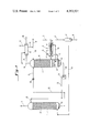
- FIG. 1 is a diagrammatic flowsheet illustrating one embodiment of the invention.
- FIG. 2 is a graph showing the outlet concentration of CO 2 and H 2 S in the purified gas at a constant steam/gas ratio as the solution/gas ratio varies over a wide range
- FIG. 3 is a diagrammatic flowsheet illustrating a second embodiment of the invention.
- the scrubbing system comprises an absorption column 1 and a regeneration column 2 between which the scrubbing solution is continuously circulated.
- the raw feed gas containing CO 2 and H 2 S in a CO 2 :H 2 S molar ratio of 4:1 or higher enters the system through line 3.
- the invention is particularly applicable to the selective desulfurization of gases in which the CO 2 :H 2 S molar ratio is at least 6:1 and most typically the invention will find its most advantageous application to gases which contain from 4% to 35% CO 2 and from 0.4% to 2% H 2 S in a CO 2 :H 2 S molar ratio of from 6:1 to 30:1.
- gases produced by the pressure gasification of sulfur containing coal, oil, fuel gases or other carbonaceous materials by reaction of such materials with steam and air, or steam and oxygen are typical of the type of gases which are advantageously selectively desulfurized by means of the invention.
- gases after preliminary treatment to remove soot, ash, and the like are at a high temperature and are saturated with steam.
- gases are preferably desulfurized under pressure and without cooling to low temperatures.
- removal of a high proportion of the H 2 S content and a relatively lower proportion of the CO 2 content is possible without loss of pressure and without cooling to low temperatures.
- the raw feed gas is hot and saturated with steam as it enters the system and the heat contained in the feed gas is used to heat the scrubbing solution to generate stripping steam.
- the hot feed gas passes through tube bundle 4 of the reboiler designated generally by the numeral 5 (to be described below) where heat is transferred to the scrubbing solution to generate steam.
- the feed gas leaves reboiler 5 by line 6 and after passing through knock-out drum 7, where condensate is removed and leaves the system by line 8, flows by line 9 to the bottom of absorption column 1.
- Column 1 is suitably equipped in the cross-hatched portion designated by the letter A with means for producing intimate gas-liquid contact.
- Section A is provided with packing materials such as Raschig rings, Berl saddles, Intalox saddles, Pall rings or other types of bodies exposing a large surface of liquid to the gas flowing through the packing.
- packing materials such as Raschig rings, Berl saddles, Intalox saddles, Pall rings or other types of bodies exposing a large surface of liquid to the gas flowing through the packing.
- other means such as contact trays, e.g., sieve trays, may be employed for insuring intimate gas-liquid contact.
- the absorption column should operate at substantial superatmospheric pressures of at least 100 pounds per square inch gage (psig) and preferably at least 200 psig. Absorption pressures in most typical applications will range from 250 to 1500 psig.
- Optimum scrubbing solution temperatures in the absorption zone will depend on a number of factors. It is generally preferable in a power cycle type application to treat the raw feed gas at the highest temperature possible, namely, at the temperature prevailing in the regeneration column. It may be desirable, however, in some cases to operate the absorber at somewhat lower temperatures. For example, if the feed gas contains a high partial pressure of carbon monoxide, the formation of potassium formate may become a problem at high absorption temperatures. This problem can be greatly mitigated by operating the absorber at somewhat reduced temperatures by reducing the temperature of the feed gas, by cooling the hot solution from the regenerator before introduction into the absorber, or both.
- FIG. 3 illustrates a system designed to operate at lower absorption temperatures and will be described in detail below.
- the absorber temperatures to be used in the system of the invention will range broadly from 60° C. to 140° C. and will preferably range in the most typical applications from 80° C. to 120° C.
- the temperature of the solution in various portions of the absorber column may vary considerably due to the differing temperatures of the stream or streams of solution entering the absorber, the temperatures and steam content of the feed gas entering the bottom of the absorber, and the heat of absorption of the CO 2 and H 2 S absorbed in the column. Most typically, the solution temperature will be lowest at the top of the absorber and highest at the bottom.
- the ranges of absorption temperatures given above refer to the mean solution temperature in the mass transfer section (viz. Section A) of the absorber.
- the scrubbing solution containing absorbed CO 2 and H 2 S accumulates at the bottom of column 1 in sump 12 and is conducted by line 13 to a pressure letdown valve 14 where the pressure is reduced to that prevailing at the top of regenerator tower 2, and the depressurized solution then flows into the top of regenerator tower 2 by line 15.
- the scrubbing solution is a relatively concentrated solution of an alkali metal carbonate, particularly potassium or sodium carbonate.
- concentrated potassium carbonate solutions having potassium carbonate concentrations of 15% to 45% and preferably 20% to 35% by weight (these concentrations being calculated on the assumption that all potassium is present as potassium carbonate).
- Such solutions may contain corrosion inhibitors such as small amounts of potassium vanadate.
- Additives which increase the rate of desorption such as ethanolamines, amino acids, such as glycine, relatively large amounts of As 2 O 3 , are preferably omitted from the solution since such additives increase the rate of CO 2 desorption more than they increase the rate of H 2 S desorption and consequently make it more difficult to achieve selective absorption of H 2 S.
- the pressure in the regeneration column should be in the vicinity of atmospheric. In some applications it is advantageous to place the regenerator under a small positive pressure up to about 40 pounds per square inch absolute (psia) so that the effluent gases leaving by line 16 (principally steam plus CO 2 and H 2 S) can be delivered to their point of utilization (such as Claus plant) without the use of a compressor. In other cases pressures slightly below atmospheric may be desirable. Regenerator pressures will generally range from 9 psia to 40 psia and preferably 18 psia to 25 psia as measured at the top of the regenerator.
- the regenerated solution after steam stripping in Section B, collects at the bottom of regeneration column 2 on a trapout tray 17.
- Solution is withdrawn from tray 17 by line 18 and circulated through reboiler 5 where it passes over tube bundle 4 supplied with hot saturated feed gas.
- Steam generated by contact of the solution with tube bundle 4 is introduced into the bottom of the regenerator column by line 9 and flows upwardly through the column countercurrent to descending solution.
- the scrubbing solution overflows weir 20 and is withdrawn from the reboiler by line 21 and introduced into the bottom of regenerator column 2 where it collects in sump 22. From sump 22, the hot regenerated solution is returned via line 23, recycle pump 24, line 25 and line 10 to the top of absorber column 1.
- the mixture of desorbed gases and steam passes out of the top of the regenerator by line 16 and flows to a condensor 26 cooled by a cooling medium supplied by line 27 and leaving by line 28.
- Sufficient water is condensed to maintain water balance in the scrubbing system, the water condensate being fed by lines 29 and 30 to the top of the regenerator. Excess condensate may be purged by line 31.
- the partially cooled gas stream consisting principally of CO 2 , H 2 S and water vapor leaves the system by line 32.
- this mixture will be treated in a Claus unit, or other suitable unit, to recover the sulfur content by oxidation of the H 2 S to elemental sulfur.
- the selective absorption of the H 2 S will result in a regenerator off-gas that is enriched in H 2 S and accordingly more amenable to economic treatment to convert the H 2 S to elemental sulfur and avoid air pollution problems.
- the steam/gas ratio is adjusted to a value to provide the desired residual partial pressure of H 2 S in the purified gas.
- the partial pressure of H 2 S in the purified gas depends essentially only on the steam/gas ratio and is independent of other system operating variables over wide ranges.
- the proper steam/gas ratio will be that which reduces the equilibrium partial pressure of H 2 S above the regenerated solution at the bottom of the regenerator to a value which will provide the desired residual H 2 S partial pressure in the purified gas.
- the outlet partial pressure of H 2 S at the top of the absorber will be essentially the same as, or only slightly higher than, the equilibrium partial pressure of H 2 S above the regenerated solution at the temperature it is delivered to the top of the absorber. If there is no cooling of the solution between the regenerator and the absorber, the equilibrium pressure of H 2 S above the regenerated solution at the bottom of the regenerator should be the same as, or only slightly lower than, the desired partial pressure of H 2 S at the top of the absorber.
- a lower steam/gas ratio can be employed (for a given desired H 2 S partial pressure in the purified gas) since cooling of the solution reduces the H 2 S partial pressure above the solution.
- the solution is regenerated to the point at which, after cooling, the equilibrium partial pressure over the regeneration solution is equal to, or only slightly lower than, the desired partial pressure of H 2 S in the purified gas.
- the proper value of such steam/gas ratio can be determined empirically or by calculation using the known equilibrium pressures of H 2 S over alkali metal carbonate solutions, while taking into consideration the following factors.
- First, the steam/gas ratio will be directly proportional to the quantity of H 2 S to be removed from the gas.
- a third factor influencing the steam/gas ratio is the degree to which the solution is cooled, if at all, between the regenerator and the absorber. As pointed out above, cooling of the solution reduces the equilibrium partial pressure of H 2 S above the solution and this in turn permits the use of a lower steam/gas ratio to achieve a given level of H 2 S partial pressure in the purified gas.
- a fourth factor influencing the steam/gas ratio is the pressure at the bottom of the regenerator. In general, the required steam/gas ratio increases with increasing regenerator pressure since the H 2 S partial pressure in the regenerator increases in direct proportion to the pressure, requiring larger quantities of steam to reduce the H 2 S partial pressure to a level at which further desorption will occur.
- the next element in the procedure is to maintain the selected steam/gas ratio substantially constant by increasing or decreasing the stripping steam flow to the regenerator proportionately as the feed gas flow to the absorber varies.
- the feed gas heats the reboiler 5, and the reboiler system should be designed to generate stripping steam in direct proportion to the flow rate of the feed gas.
- the reboiler system 5 is of course shown diagrammatically only and it is understood that suitable means are provided to insure that stripping steam production will vary in direct proportion to the rate of feed gas flow, such as by providing variable areas of heat exchange surface exposed to the gas flow as the rate of gas flow varies.
- the stripping steam may of course be provided other than by a reboiler heated by the hot feed gas as shown in FIG. 1. Regardless of the source of the stripping steam, means should be provided to maintain a constant steam/gas ratio, viz. the ratio of stripping steam fed to the bottom of the regenerator to the feed gas fed to the bottom of the absorber. With the steam/gas ratio controlled at a constant value, the concentration of H 2 S in the purified gas will remain constant at the preselected value although other operating variables, such as the solution/gas ratio, vary over wide ranges as will be shown in the examples below.
- the next element in the procedure is to adjust the solution/gas ratio (viz. the ratio of the rate of scrubbing solution flow circulating in the system to the rate of gas flow to the absorber) to a value in the vicinity of that at which the partial pressure of H 2 S in the purified gas remains at the desired selected value and at which the difference between the partial pressure of CO 2 and H 2 S reaches a maximum value.
- the solution/gas ratio viz. the ratio of the rate of scrubbing solution flow circulating in the system to the rate of gas flow to the absorber
- the residual partial pressure of H 2 S in the purified gas remains essentially constant over a wide range of solution/gas ratios, (except for the lowest range of solution/gas ratios where the residual H 2 S partial pressure will vary rapidly).
- the partial pressure of CO 2 in the purified gas over the same range of solution/gas ratios, undergoes a continuous large change and reaches a relatively high value over the range at which the H 2 S partial pressure remains at a pre-selected constant value.
- the solution/gas ratio at which maximum selectivity occurs will vary considerably depending on factors such as the composition of the gas to be purified, particularly the absolute concentrations of CO 2 and H 2 S, the CO 2 :H 2 S ratio in the feed gas, and the desired residual partial pressure of H 2 S in the purified gas.
- the desired solution/gas ratio can be determined empirically by varying the solution/gas ratio while holding the steam/gas ratio constant, or it may be determined by calculation using the following general stepwise procedure.
- the steam/gas ratio in the regenerator is a function only of the amount of H 2 S in the raw gas, the partial pressure of H 2 S in the purified gas, the regenerator pressure and the solution temperature entering the absorber. It is independent of the amount of CO 2 removed and other operating parameters.
- the H 2 S content determined in this manner should be slightly lower than the H 2 S content determined in step one. If not the solution/gas ratio is increased to provide the desired H 2 S partial pressure in the purified gas. Based on the values determined by the above procedure the amount of mass transfer capacity required in the regenerator can be determined. The capacity required will be that necessary to change the CO 2 content of the solution between the top and the bottom of the regenerator by the differential amount determined as described above using known techniques based on equilibrium pressures of CO 2 and mass transfer rates for CO 2 desorption. If the mass transfer capacity of the regenerator is less than that required to removed the differential amount of CO 2 it will be kinetically limited with respect to CO 2 removal, and as already discussed, the H 2 S selectivity will be further improved. The mass transfer capacity of the regenerator must, of course, be sufficient to remove the required amount of H 2 S that will provide the desired H 2 S partial pressure in the purified gas.
- the next element of the procedure is to maintain the selected solution/gas ratio at a constant value by adjusting the solution flow in direct proportion to variations in the rate of feed gas flow to the absorber.
- this is accomplished by increasing or decreasing the solution circulation rate by suitably regulating circulating pump 24 as the rate of feed gas flow into the bottom of the absorber through line 9 respectively increases or decreases.
- Suitable instrumentation and controls to regulate automatically the solution circulation rate in proportion to feed gas ratio will be of course be used in the design and operation of a commercial plant.
- Constant H 2 S selectivity means of course a constant composition for the purified gas and for the regenerator off-gases.
- a constant CO 2 and H 2 S level in the fuel gas delivered to the cycle is of great importance.
- a constant, maximized level of CO 2 in the gas is important from the standpoint of maximizing energy recovery, while a constant, minimized level of H 2 S is important from the standpoint of avoiding air pollution and of avoiding damage to gas turbine blades often used in such power cycles.
- Constant composition of the regenerator off-gases is important in avoiding operating problems in the sulfur recovery plant where such off-gases are treated.
- the selectivity of H 2 S absorption is further enhanced by limiting the mass transfer volume of the regenerator to restrict the desorption of CO 2 . Because of the much higher rate of H 2 S desorption compared with CO 2 desorption it has been found that the mass transfer capacity requirements for H 2 S desorption are satisfied with far less capacity than for CO 2 , and by restricting the mass transfer capacity in the regenerator, the CO 2 desorption may be limited. This means in turn that less CO 2 will be absorbed in the absorber since the regenerated scrubbing solution returned to the absorber will be more saturated in CO 2 , with the result that higher H 2 S selectivity is obtained.
- the desired limitation in mass transfer capacity can be measured by the difference in temperature between the vapors leaving the top of the regenerator mass transfer section (Section B in FIG. 1) and the "after flash” temperature of the scrubbing solution.
- the "after flash” temperature of the scrubbing solution is the temperature of the solution immediately after the flashing that occurs on depressurization, that is the solution temperature at the top of the regenerator mass transfer section.
- the mass transfer capacity is limited such that the vapor/liquid temperature difference defined above is in the range of from 2° C. to 10° C. and preferably from 4° C. to 8° C.
- Sufficient mass transfer capacity must, of course, always be provided to permit the desired desorption of H 2 S and this imposes a lower limit on the amount of mass transfer capacity in the regenerator.
- the equilibrium pressure of H 2 S increases only slightly as the solution passes through the absorber column; the extent of H 2 S removal is fixed by the H 2 S equilibrium pressure at the top of the absorber; and the partial pressure of H 2 S in the gas phase exceeds the H 2 S equilibrium pressure throughout the remainder of the absorber tower.
- CO 2 a relatively large amount of CO 2 is absorbed by the solution and the regenerated solution contains a relatively large amount of CO 2 .
- the equilibrium pressure of CO 2 increases sharply as the solution passes through the absorber tower and, at any given solution/gas ratio, the CO 2 equilibrium pressure will approach the CO 2 partial pressure in the feed gas and further CO 2 absorption will cease regardless of the CO 2 residence time in the absorber.
- the partial pressure of CO 2 in the purified gas becomes a function of the solution/gas ratio because of the equilibrium barrier that is set up limiting futher CO 2 absorption.
- the H 2 S partial pressure in the purified gas on the other hand remains independent of the solution/gas ratio over a wide range.
- the following example illustrates the application of the invention for the purification of a hot, saturated gas mixture produced by the pressure gasification of a sulfur containing coal with steam and air.
- the gas is employed as feed gas to a so-called combined power cycle where the gas is first burned in a gas turbine and then passed through heat exchange units to generate steam which is in turn employed to operate steam turbines.
- the combined power cycle has a variable load demand which results in a fourfold variation in feed gas flow to the power cycle with major changes in load demand and corresponding gas flow occurring in a matter of minutes a number of times a day.
- the raw feed gas from the pressure gasifier is first water scrubbed to remove tars and particulates with recovery of the heat in the hot gas in the form of saturated steam.
- the hot, saturated gas from the water scrubber has a flow rate (on a dry basis) varying between 6675 pound mols per hour (lb. mols/hr.) at minimum flow and 26,700 lb. mols/hr. at maximum flow, is at a temperature of 185° C. and is saturated with water vapor. It has the following composition (on a dry basis):
- the above raw feed gas is introduced into a system of the type shown in FIG. 1, flowing first through reboiler system 5 and then flowing into the bottom of the absorber at a temperature of 121° C. and under a pressure of 300 psig.
- the mass transfer capacity of the absorber is designed to take the maximum gas flow of 26,700 lb. mols/hr. with sufficient capacity so that it is not kinetically limited. This is accomplished by providing 2,455 cubic feet of packing consisting of pall rings 2 inches in diameter and length arranged in a bed 12.5 feet in diameter and 20 feet deep.
- the absorbent solution consists of an aqueous solution of potassium carbonate containing 30% by weight potassium carbonate.
- the desired level of H 2 S in the purified gas is selected as 0.08% (a partial pressure of H 2 S in the purified gas of 0.24 psi).
- the amount of stripping steam to achieve this level of H 2 S in the purified gas is determined to be 142,750 pounds per hour (saturated steam at 14.7 psi having a heat content of 950 BTU per pound) at the maximum gas flow of 26,700 lb. mols/hr. That flow of stripping steam is introduced at the bottom of a regenerator equipped with a mass transfer section packed with 4,295 cubic feet of pall ring packing 2 inches in diameter and length and arranged in a bed 12.5 feet in diameter and 35 feet deep. Pressure at the top of the regenerator is 8 psig.
- the H 2 S concentration in the purified gas remains at a constant value of 0.08% (0.24 psi partial pressure) over most of the range of solution flow rates, namely from point A (solution flow rate of 2,600 gallons/minute) to point B (solution flow rate of 9,100 gallons/minute). Over the lowest solution flow rates, viz. from zero to 1,800 gallons/minute, the H 2 S concentration drops rapidly from the initial concentration in the raw gas, viz. 1% to the desired value of 0.08% at 2,600 gallons/minute.
- the CO 2 concentration in the purified gas undergoes a continuous and several-fold change over the same range of solution flow rates at which the H 2 S concentration remains constant at 0.08%, undergoing a continuous increase as the solution flow rate decreases from point B to point A.
- the selectivity of H 2 S absorption can be maximized by selecting the solution/gas ratio in the vicinity of point A where the partial pressure of H 2 S in the purified gas remains at the desired value and where the difference between the partial pressure of CO 2 and H.sub. 2 S in the purified gas reaches a maximum level.
- Both the selected solution/gas ratio and the selected steam/gas ratio are then maintained constant as gas flow varies.
- both H 2 S concentration and CO 2 concentration in the purified gas remain constant despite a four-fold change in the gas flow rate, that is, as the gas flow varies from 6675 to 26,700 lb. mols/hr.
- the concentration of H 2 S in the purified gas remains substantially constant at a value of 0.08% (a partial pressure of 0.24 psi) representing 92.5% H 2 S removal
- the CO 2 concentration similarly remains substantially constant at a value of about 10.6% (a partial pressure of 31.8 psi) representing only 33.6% CO 2 removal.
- the mass transfer capacity of the regenerator is such that the regeneration of the solution is kinetically limited with respect to CO 2 desorption with the result that the temperature of the gases leaving the top of the regenerator is 4.4° C. higher than the after flash temperature of the scrubbing solution at the top of the regenerator.
- Example 1 The operating conditions of Example 1 are duplicated in all respects except that the regenerator is provided with a much larger mass transfer capacity. Instead of a section packed with 4,295 cubic feet of pall ring packing 2 inches in diameter and length and arranged in a bed 12.5 feet in diameter and 35 feet deep, a section was used packed with 11,045 cubic feet of the same packing in a bed 12.5 feet in diameter and 90 feet deep (approximately 2.6 times as much transfer capacity as in Example 1). With this additional mass transfer capacity, the kinetic limitation with respect to CO 2 desorption is substantially eliminated and the temperature differential between the after flash solution temperature and the temperature of the gas phase at the top of the regenerator is reduced to 1.7° C.
- Example 1 The operating conditions of Example 1 are duplicated in all respects except that the regenerator is provided with a smaller mass transfer capacity. Using the same packing as in Example 1, and the same bed diameter, the depth of the bed was reduced from 35 feet to 20 feet with the result that the regenerator became more kinetically limited with respect to CO 2 absorption and the temperature differential between the after flash solution temperature and the temperature of the gas phase at the top of the regenerator increased from 4.4° C. to 4.7° C. Under these conditions the point of maximum selectivity occurs at the same solution/gas ratio, but less CO 2 is absorbed with the result that there is higher H 2 S selectivity and the regenerator off gas is richer in H 2 S.
- the following table summarizes the results of Example 3 compared to Example 1:
- FIG. 3 of the drawings showing a second embodiment of the invention.
- the system of FIG. 3 includes a two stage regeneration system in which a minor portion of the scrubbing solution is subjected to a higher degree of regeneration and also includes means for cooling the regenerated scrubbing solution as it is recycled from the regenerator to the absorber.
- the system of FIG. 3, operating at a lower absorption temperature permits the H 2 S level in the purified gas to be reduced to a lower level while still maintaining good H 2 S selectivity.
- the system of FIG. 3 comprises an absorber 33 having two mass transfer sections C and D equipped with suitable packing materials to promote intimate gas-liquid contact, and a regeneration column 34 having similarly equipped mass transfer sections E and F.
- the raw hot feed gas enters the system by line 35 and passes through tube bundle 36 of reboiler 37 where stripping steam is generated.
- the partially cooled feed gas leaves the reboiler by line 38, passes through a knock-out drum 39, where condensate is removed and leaves the system by line 40. It then flows by line 41 to a boiler feed water heater 42 where further heat is abstracted from the gas before it is delivered to the bottom of the absorber by line 43.
- the raw gas flows upwardly through the absorption column countercurrent to the scrubbing solution introduced into the absorption column by lines 44 and 45 and the purified gas leaves by line 46.
- the spent scrubbing solution containing absorbed CO 2 and H 2 S accumulates at the bottom of the column in sump 47 from where it is conducted by line 48, pressure let-down valve 49, and line 50, to the top of regenerator 34 operating at a pressure in the vicinity of atmospheric.
- regenerator 34 the scrubbing solution is steam-stripped in two sections. In the upper section, provided with mass transfer Section E, all of the solution is subjected to countercurrent contact with stripping steam introduced into the bottom of the column. The solution then collects on chimney tray 51. The major portion of the solution usually from 60% to 90% of the total at an intermediate stage of regeneration, is drawn off from chimney tray 51 by line 52, passes through a cooler 53 and is then recycled by pump 54 and line 45 to an intermediate level in the absorber above mass transfer Section D.
- a minor portion of the solution usually from 10% to 40% of the total overflows chimney tray 51 and flow downwardly into the lower portion of the regenerator equipped with mass transfer Section F where it is subjected to further steam stripping.
- the more thoroughly regenerated minor portion of the circulating solution collects at the bottom of the regenerator on trapout tray 55.
- Solution is withdrawn from tray 55 by line 56 and circulated through reboiler 37 where it passes over tube bundle 36 heated by the hot feed gas.
- Steam generated by contact of the solution with tube bundle 36 is introduced into the bottom of the regenerator by line 57 and flows upwardly through mass transfer Section F, passes through chimney tray 51 as shown by the arrows, and then passes upwardly through mass transfer Section E.
- the mixture of steam and desorbed gases collecting at the top of the regenerator is removed by line 64 and flows to a condenser 65 cooled by a cooling medium supplied by line 66 and leaving by line 67.
- a condenser 65 cooled by a cooling medium supplied by line 66 and leaving by line 67.
- sufficient water is condensed to maintain water balance in the scrubbing system, the water condensate being fed by line 68 and 69 to the top of the regenerator.
- Excess condensate may be purged through line 70.
- the partially cooled mixture consisting principally of steam, H 2 S and CO 2 leaves the system by line 71 for any desired further treatment.
- the operation of the system of FIG. 3 is similar to that of FIG. 1 already described in detail and will be illustrated by Example 4.
- the system of FIG. 3 is generally preferred in those cases where it is desired to reduce the residual partial pressure of H 2 S in the purified gas to a low level and still maintain good H 2 S selectivity, or where a lower absorption temperature is desired to prevent the production of potassium formate through the reaction of carbon monoxide with potassium carbonate, or both.
- a lower absorption temperature of course requires that the feed gas be cooled to a lower temperature and for this reason, a boiler feed water heater 42 is employed to recover heat from the feed gas while lowering its temperature.
- a lower residual partial pressure of H 2 S in the purified gas while keeping the amount of stripping steam at a reasonable level is possible with the system of FIG. 3 since the solution fed to the top of the absorber is more thoroughly regenerated and is at a reduced temperature, both of which reduce the equilibrium partial pressure of H 2 S above the regenerated solution.
- the required steam/gas ratio required is substantially reduced since only a minor portion of the solution is thoroughly regenerated and because cooling is used to reduce the equilibrium partial pressure of H 2 S above the solution at the top of the absorber.
- This example illustrates the use of the system of FIG. 3 for the purification of a gas mixture produced by the pressure gasification of coal which has the following composition after water scrubbing to remove tar and particulates:
- the purified gas is used as the feed gas to a combined power cycle where the gas is burned and passed through gas turbines and steam generation units.
- the variable load demand of the power cycle results in a fourfold variation in feed gas flow to the purification unit with the flow changes occurring over short time intervals.
- the raw gas feed to the reboiler through line 35 is 18,000 lb. mols. per hour (dry basis) of gas of the above composition at a temperature of 148° C. and a pressure of 320 psig and saturated with water vapor.
- the rate is 4500 lb. mols. per hour (dry basis).
- the level of H 2 S purity in the purified gas is selected at 0.0175% (a partial pressure of H 2 S in the purified gas of 0.055 psi).
- the amount of stripping steam to achieve this level of H 2 S in the purified gas is 50,525 pounds per hour (saturated steam at 14.7 psi having a heat content of 950 BTU per pound) at the maximum gas flow of 18,000 lb. mols./hr.
- the steam/gas ratio is held substantially constant, namely at a value of 2.8 pounds of steam per lb. mol. of gas flow.
- That amount of stripping steam generated in reboiler 37 by the hot feed gas is introduced into the bottom of the regenerator through line 57 and flows upwardly through mass transfer section F consisting of a packed bed 8.0 feet in diameter and 20 feet high equipped with metal pall rings two inches in diameter and length, and then, after passing through chimney tray 51, flows upwardly through mass transfer section E consisting of a packed bed 8.0 feet in diameter and 30 feet high also equipped with metal pall rings two inches in diameter and length.
- the pressure at the top of the regenerator is 4.5 psig while the pressure at the bottom is 6.5 psig.
- the hot feed gas After passing through tube bundle 36 of reboiler 35, the hot feed gas passes through boiler feed water heater 42 where its temperature is reduced to 85° C. and then enters absorber 33 at a pressure of 310 psig through line 43 and passes upwardly through mass transfer section D consisting of a packed bed 9.0 feet in diameter and 25 feet high equipped with metal pall rings two inches in diameter and length and mass transfer section C consisting of a packed bed 9.0 feet in diameter and 15 feet deep equipped with metal pall rings 11/2 inches in diameter and length.
- the absorbed solution is a 30% by weight aqueous potassium carbonate solution.
- the absorber is supplied at the maximum gas flow rate by line 44 with 388 gallons per minute (gpm) of regenerated scrubbing solution which leaves the bottom of regenerator tower 34 by line 61 at a temperature of 114.5° C. and is cooled in cooler 62 to 85° C. at which temperature it enters the top of the absorber.
- the absorber is also supplied at maximum gas flow rate by line 45 with 776 gpm of less thoroughly regenerated solution which leaves the regenerator by line 52 at a temperature of 110° C. and is cooled in cooler 53° to 85° C. at which temperature it enters the absorber.
- the solution leaves the bottom of the absorber at a temperature of 95° C. and is recycled to the top of the regenerator.
- the total solution flow to the absorber is 1164 gpm at the full gas feed rate of 18000 lb. mols./hr. and this flow is varied in response to changes in gas flow so that the solution/gas ratio is maintained substantially constant, namely at a value of 3.9 gallons per lb. mol. of gas flow.
- the H 2 S content of the purified gas is maintained at a substantially constant value of 0.0175% (partial pressure of 0.055 psi) while the CO 2 content of the purified gas is maintained substantially constant at 3.18% (partial pressure of 10.05 psi) regardless of variations in the gas flow.
- the solution/gas ratio is increased above the value of 3.9 gallons per lb. mol. of gas flow, the H 2 S content of the purified gas remains constant but the CO 2 content steadily increases, thus decreasing the H 2 S selectivity.
- the solution/gas ratio of 3.9 gallons per minute thus represents the operating condition where optimum H 2 S selectivity is obtained while the H 2 S content in the purified gas is maintained at the desired low value of 0.00175% (partial pressure of 0.055 psi).
- Example 4 In contrast to Example 1 it will be noted that in this Example 4, the H 2 S content in the purified gas is reduced to a considerably lower value (an H 2 S partial pressure of 0.055 psi in this Example 4 versus an H 2 S partial pressure of 0.24 in Example 1) while still obtaining a good H 2 S selectivity ratio and an economical steam/gas ratio.
- This result is obtained by the use of the two stage absorber and regenerator system shown in FIG. 3 where a portion of the solution is more thoroughly regenerated and fed to the top of the absorber and where all of the solution as well as the entering raw gas is cooled to 85° C.
- the use of the lower absorption temperature in this Example 4 also reduced the rate of formation of potassium formate to a substantially lower value.
Landscapes
- Chemical & Material Sciences (AREA)
- Engineering & Computer Science (AREA)
- Analytical Chemistry (AREA)
- General Chemical & Material Sciences (AREA)
- Oil, Petroleum & Natural Gas (AREA)
- Chemical Kinetics & Catalysis (AREA)
- Health & Medical Sciences (AREA)
- Biomedical Technology (AREA)
- Environmental & Geological Engineering (AREA)
- Gas Separation By Absorption (AREA)
- Treating Waste Gases (AREA)
- Industrial Gases (AREA)
Priority Applications (6)
| Application Number | Priority Date | Filing Date | Title |
|---|---|---|---|
| US06/176,203 US4293531A (en) | 1980-08-07 | 1980-08-07 | Selective removal of H2 S from gas mixtures containing CO2 and H2 S |
| CA382,546A CA1133234A (en) | 1980-08-07 | 1981-07-24 | Selective removal of h.sub.2s from gas mixtures containing co.sub.2 and h.sub.2s |
| EP81303593A EP0046061B1 (de) | 1980-08-07 | 1981-08-06 | Verfahren zur selektiven Abscheidung von Schwefelwasserstoff aus Gasmischungen, die Kohlendioxid und Schwefelwasserstoff enthalten |
| DE8181303593T DE3167085D1 (en) | 1980-08-07 | 1981-08-06 | Method for selectively removing hydrogen sulfide from gas mixtures containing carbon dioxide and hydrogen sulfide |
| AT81303593T ATE10169T1 (de) | 1980-08-07 | 1981-08-06 | Verfahren zur selektiven abscheidung von schwefelwasserstoff aus gasmischungen, die kohlendioxid und schwefelwasserstoff enthalten. |
| AU73849/81A AU543349B2 (en) | 1980-08-07 | 1981-08-06 | Removing h2s from gas mixtures containing co2 and h2s |
Applications Claiming Priority (1)
| Application Number | Priority Date | Filing Date | Title |
|---|---|---|---|
| US06/176,203 US4293531A (en) | 1980-08-07 | 1980-08-07 | Selective removal of H2 S from gas mixtures containing CO2 and H2 S |
Publications (1)
| Publication Number | Publication Date |
|---|---|
| US4293531A true US4293531A (en) | 1981-10-06 |
Family
ID=22643411
Family Applications (1)
| Application Number | Title | Priority Date | Filing Date |
|---|---|---|---|
| US06/176,203 Expired - Lifetime US4293531A (en) | 1980-08-07 | 1980-08-07 | Selective removal of H2 S from gas mixtures containing CO2 and H2 S |
Country Status (6)
| Country | Link |
|---|---|
| US (1) | US4293531A (de) |
| EP (1) | EP0046061B1 (de) |
| AT (1) | ATE10169T1 (de) |
| AU (1) | AU543349B2 (de) |
| CA (1) | CA1133234A (de) |
| DE (1) | DE3167085D1 (de) |
Cited By (13)
| Publication number | Priority date | Publication date | Assignee | Title |
|---|---|---|---|---|
| US4469668A (en) * | 1982-01-29 | 1984-09-04 | Spevack Jerome S | Integrated system for pollution abatement and energy derivation from geothermal steam |
| US4499059A (en) * | 1983-11-16 | 1985-02-12 | Mobil Oil Corporation | In-line injection of alkaline absorbant to remove H2 S |
| US4569194A (en) * | 1979-08-27 | 1986-02-11 | General Electric Company | Integrated coal-fired gas turbine power plant |
| WO1987001962A1 (fr) * | 1985-10-04 | 1987-04-09 | Societe Nationale Elf Aquitaine (Production) | Procede et dispositif pour l'extraction selective de l'h2s d'un gaz en contenant |
| US4968488A (en) * | 1982-01-29 | 1990-11-06 | Spevack Jerome S | Integrated system for pollution abatement and energy derivation from steam |
| US5397556A (en) * | 1992-12-16 | 1995-03-14 | The Regents Of The Unviversity Of California | Process for recovery of sulfur from acid gases |
| RU2197319C2 (ru) * | 1999-06-18 | 2003-01-27 | ОАО "Газпром" | Установка очистки газа от кислых компонентов |
| WO2006118795A1 (en) * | 2005-04-29 | 2006-11-09 | Fluor Technologies Corporation | Configurations and methods for acid gas absorption and solvent regeneration |
| US20070283813A1 (en) * | 2004-03-15 | 2007-12-13 | Masaki Iijima | Co2 Recovery System And Method |
| US20100135881A1 (en) * | 2009-07-28 | 2010-06-03 | Lubo Zhou | Process for simultaneous removal of carbon dioxide and sulfur oxides from flue gas |
| US10150926B2 (en) | 2013-12-12 | 2018-12-11 | Fluor Technologies Corporation | Configurations and methods of flexible CO2 removal |
| US10359230B2 (en) | 2012-10-24 | 2019-07-23 | Fluor Technologies Corporation | Integration methods of gas processing plant and nitrogen rejection unit for high nitrogen feed gases |
| US10384160B2 (en) | 2010-02-17 | 2019-08-20 | Fluor Technologies Corporation | Configurations and methods of high pressure acid gas removal in the production of ultra-low sulfur gas |
Families Citing this family (2)
| Publication number | Priority date | Publication date | Assignee | Title |
|---|---|---|---|---|
| RU2134149C1 (ru) * | 1997-11-12 | 1999-08-10 | Институт нефтехимии и катализа с опытным заводом АН РБ | Поглотительный раствор для очистки газов от сероводорода |
| AT514460B1 (de) | 2013-06-20 | 2015-03-15 | Univ Wien Tech | Verfahren und Vorrichtung zur Entschwefelung von Gasgemischen |
Citations (6)
| Publication number | Priority date | Publication date | Assignee | Title |
|---|---|---|---|---|
| US2886405A (en) * | 1956-02-24 | 1959-05-12 | Benson Homer Edwin | Method for separating co2 and h2s from gas mixtures |
| US3338664A (en) * | 1961-12-27 | 1967-08-29 | Shell Oil Co | Method of separating acidic components from gaseous mixtures |
| US3725529A (en) * | 1968-07-13 | 1973-04-03 | Vetrocoke Cokapuania Spa | PROCESS FOR ELIMINATING Co2 AND/OR H2s FROM GASEOUS MIXTURES |
| US3931389A (en) * | 1971-06-04 | 1976-01-06 | Metallgesellschaft Aktiengesellschaft | Process of desulfurizing hot gases |
| US3958943A (en) * | 1971-06-01 | 1976-05-25 | Societe Nationale Des Petroles D'aquitaine | Process to purify gas containing hydrogen sulphide by means of amines |
| US4106916A (en) * | 1977-08-10 | 1978-08-15 | Phillips Petroleum Company | Automatic control of an absorption/stripping process |
Family Cites Families (1)
| Publication number | Priority date | Publication date | Assignee | Title |
|---|---|---|---|---|
| US4160810A (en) * | 1978-03-07 | 1979-07-10 | Benfield Corporation | Removal of acid gases from hot gas mixtures |
-
1980
- 1980-08-07 US US06/176,203 patent/US4293531A/en not_active Expired - Lifetime
-
1981
- 1981-07-24 CA CA382,546A patent/CA1133234A/en not_active Expired
- 1981-08-06 AT AT81303593T patent/ATE10169T1/de not_active IP Right Cessation
- 1981-08-06 AU AU73849/81A patent/AU543349B2/en not_active Ceased
- 1981-08-06 EP EP81303593A patent/EP0046061B1/de not_active Expired
- 1981-08-06 DE DE8181303593T patent/DE3167085D1/de not_active Expired
Patent Citations (6)
| Publication number | Priority date | Publication date | Assignee | Title |
|---|---|---|---|---|
| US2886405A (en) * | 1956-02-24 | 1959-05-12 | Benson Homer Edwin | Method for separating co2 and h2s from gas mixtures |
| US3338664A (en) * | 1961-12-27 | 1967-08-29 | Shell Oil Co | Method of separating acidic components from gaseous mixtures |
| US3725529A (en) * | 1968-07-13 | 1973-04-03 | Vetrocoke Cokapuania Spa | PROCESS FOR ELIMINATING Co2 AND/OR H2s FROM GASEOUS MIXTURES |
| US3958943A (en) * | 1971-06-01 | 1976-05-25 | Societe Nationale Des Petroles D'aquitaine | Process to purify gas containing hydrogen sulphide by means of amines |
| US3931389A (en) * | 1971-06-04 | 1976-01-06 | Metallgesellschaft Aktiengesellschaft | Process of desulfurizing hot gases |
| US4106916A (en) * | 1977-08-10 | 1978-08-15 | Phillips Petroleum Company | Automatic control of an absorption/stripping process |
Non-Patent Citations (1)
| Title |
|---|
| U.S. Bureau of Mines Report of Investigations 5660. * |
Cited By (20)
| Publication number | Priority date | Publication date | Assignee | Title |
|---|---|---|---|---|
| US4569194A (en) * | 1979-08-27 | 1986-02-11 | General Electric Company | Integrated coal-fired gas turbine power plant |
| US4469668A (en) * | 1982-01-29 | 1984-09-04 | Spevack Jerome S | Integrated system for pollution abatement and energy derivation from geothermal steam |
| US4968488A (en) * | 1982-01-29 | 1990-11-06 | Spevack Jerome S | Integrated system for pollution abatement and energy derivation from steam |
| US4499059A (en) * | 1983-11-16 | 1985-02-12 | Mobil Oil Corporation | In-line injection of alkaline absorbant to remove H2 S |
| US4889700A (en) * | 1985-04-10 | 1989-12-26 | Societe Nationale Elf Aquitaine (Production) | Process and device for selective extraction of H2 S from an H2 S-containing gas |
| WO1987001962A1 (fr) * | 1985-10-04 | 1987-04-09 | Societe Nationale Elf Aquitaine (Production) | Procede et dispositif pour l'extraction selective de l'h2s d'un gaz en contenant |
| FR2588196A1 (fr) * | 1985-10-04 | 1987-04-10 | Elf Aquitaine | Procede et dispositif pour l'extraction selective de l'h2s d'un gaz en contenant |
| US5397556A (en) * | 1992-12-16 | 1995-03-14 | The Regents Of The Unviversity Of California | Process for recovery of sulfur from acid gases |
| RU2197319C2 (ru) * | 1999-06-18 | 2003-01-27 | ОАО "Газпром" | Установка очистки газа от кислых компонентов |
| US20070283813A1 (en) * | 2004-03-15 | 2007-12-13 | Masaki Iijima | Co2 Recovery System And Method |
| US7918926B2 (en) * | 2004-03-15 | 2011-04-05 | Mitsubishi Heavy Industries, Ltd. | CO2 recovery system and method |
| WO2006118795A1 (en) * | 2005-04-29 | 2006-11-09 | Fluor Technologies Corporation | Configurations and methods for acid gas absorption and solvent regeneration |
| US20080184887A1 (en) * | 2005-04-29 | 2008-08-07 | Fluor Technologies Corporation | Configurations and Methods for Acid Gas Absorption and Solvent Regeneration |
| EA012258B1 (ru) * | 2005-04-29 | 2009-08-28 | Флуор Текнолоджиз Корпорейшн | Устройство и способ для абсорбции кислого газа и регенерации растворителя |
| US8398748B2 (en) * | 2005-04-29 | 2013-03-19 | Fluor Technologies Corporation | Configurations and methods for acid gas absorption and solvent regeneration |
| US20100135881A1 (en) * | 2009-07-28 | 2010-06-03 | Lubo Zhou | Process for simultaneous removal of carbon dioxide and sulfur oxides from flue gas |
| US10384160B2 (en) | 2010-02-17 | 2019-08-20 | Fluor Technologies Corporation | Configurations and methods of high pressure acid gas removal in the production of ultra-low sulfur gas |
| US10359230B2 (en) | 2012-10-24 | 2019-07-23 | Fluor Technologies Corporation | Integration methods of gas processing plant and nitrogen rejection unit for high nitrogen feed gases |
| US10641549B2 (en) | 2012-10-24 | 2020-05-05 | Fluor Technologies Corporation | Integration methods of gas processing plant and nitrogen rejection unit for high nitrogen feed gases |
| US10150926B2 (en) | 2013-12-12 | 2018-12-11 | Fluor Technologies Corporation | Configurations and methods of flexible CO2 removal |
Also Published As
| Publication number | Publication date |
|---|---|
| AU7384981A (en) | 1982-02-11 |
| AU543349B2 (en) | 1985-04-18 |
| EP0046061B1 (de) | 1984-11-07 |
| DE3167085D1 (en) | 1984-12-13 |
| ATE10169T1 (de) | 1984-11-15 |
| EP0046061A1 (de) | 1982-02-17 |
| CA1133234A (en) | 1982-10-12 |
Similar Documents
| Publication | Publication Date | Title |
|---|---|---|
| US4293531A (en) | Selective removal of H2 S from gas mixtures containing CO2 and H2 S | |
| US3563696A (en) | Separation of co2 and h2s from gas mixtures | |
| DE69113711T2 (de) | Trennung von Kohlendioxyd und Stickstoff aus Verbrennungsabgasen mit Rückgewinnung von Stickstoff und Argon als Nebenprodukte. | |
| US4702898A (en) | Process for the removal of acid gases from gas mixtures | |
| US9090839B2 (en) | Method and apparatus for adjustably treating a sour gas | |
| US4152217A (en) | Amine regeneration process | |
| US3563695A (en) | Separation of co2 and h2s from gas mixtures | |
| US8206669B2 (en) | Method and apparatus for treating a sour gas | |
| US4085199A (en) | Method for removing hydrogen sulfide from sulfur-bearing industrial gases with claus-type reactors | |
| US5716587A (en) | Apparatus for removal of contaminates from a gas stream | |
| US4332596A (en) | Energy efficient scrubbing of sulfur compounds from moist gaseous mixtures | |
| JPH0617213B2 (ja) | 硫化水素含有ガス流からの硫黄回収方法 | |
| US3953578A (en) | Method for purification of industrial flue gases | |
| GB2047221A (en) | Hydrogen and sulphur by cracking hydrogen sulphide | |
| JPS61164620A (ja) | ガス流から硫化水素と二酸化炭素を除去する方法 | |
| CN101289170B (zh) | 氧化还原硫回收多用装置 | |
| US4356161A (en) | Process for reducing the total sulfur content of a high CO2 -content feed gas | |
| CN104519979A (zh) | 排出气体中污染物的再生回收 | |
| US4124685A (en) | Method for substantially complete removal of hydrogen sulfide from sulfur bearing industrial gases | |
| CA1257074A (en) | Claus residual gas cleanup using tetraethylene glycol dimethyl ether as so.sub.2 scrubbing agent | |
| US3642430A (en) | Separation of carbon dioxide and hydrogen sulfide from gas mixtures | |
| US4412977A (en) | Selective acid gas removal | |
| US3862295A (en) | Method for sorptive removal of sulfur gases | |
| CA1339974C (en) | Process for removing h2s from a gas stream | |
| CN111375274B (zh) | 一种含so2气体的处理方法及装置 |
Legal Events
| Date | Code | Title | Description |
|---|---|---|---|
| AS | Assignment |
Owner name: UNION CARBIDE CORPORATION, A CORP. OF NY. Free format text: ASSIGNMENT OF ASSIGNORS INTEREST.;ASSIGNOR:BENFIELD CORPORATION;REEL/FRAME:003912/0075 Effective date: 19810904 |
|
| STCF | Information on status: patent grant |
Free format text: PATENTED CASE |
|
| AS | Assignment |
Owner name: UOP, DES PLAINES, IL., A NY GENERAL PARTNERSHIP Free format text: ASSIGNMENT OF ASSIGNORS INTEREST.;ASSIGNOR:KATALISTIKS INTERNATIONAL, INC.;REEL/FRAME:004994/0001 Effective date: 19880916 Owner name: KATALISTIKS INTERNATIONAL, INC., DANBURY, CT, A CO Free format text: ASSIGNMENT OF ASSIGNORS INTEREST.;ASSIGNOR:UNION CARBIDE CORPORATION;REEL/FRAME:004998/0636 Effective date: 19880916 Owner name: KATALISTIKS INTERNATIONAL, INC., CONNECTICUT Free format text: ASSIGNMENT OF ASSIGNORS INTEREST;ASSIGNOR:UNION CARBIDE CORPORATION;REEL/FRAME:004998/0636 Effective date: 19880916 |