US42906A - Improvement in attachments of lantern-guards - Google Patents
Improvement in attachments of lantern-guards Download PDFInfo
- Publication number
- US42906A US42906A US42906DA US42906A US 42906 A US42906 A US 42906A US 42906D A US42906D A US 42906DA US 42906 A US42906 A US 42906A
- Authority
- US
- United States
- Prior art keywords
- slide
- lantern
- guard
- apron
- notch
- Prior art date
- Legal status (The legal status is an assumption and is not a legal conclusion. Google has not performed a legal analysis and makes no representation as to the accuracy of the status listed.)
- Expired - Lifetime
Links
- 241001465382 Physalis alkekengi Species 0.000 description 32
- 241000681094 Zingel asper Species 0.000 description 30
- 239000011521 glass Substances 0.000 description 30
- 239000004568 cement Substances 0.000 description 8
- 239000011324 bead Substances 0.000 description 4
- 238000010276 construction Methods 0.000 description 4
- 210000003141 Lower Extremity Anatomy 0.000 description 2
- OSGAYBCDTDRGGQ-UHFFFAOYSA-L calcium sulfate Inorganic materials [Ca+2].[O-]S([O-])(=O)=O OSGAYBCDTDRGGQ-UHFFFAOYSA-L 0.000 description 2
- ZOMBKNNSYQHRCA-UHFFFAOYSA-J calcium sulfate hemihydrate Chemical compound O.[Ca+2].[Ca+2].[O-]S([O-])(=O)=O.[O-]S([O-])(=O)=O ZOMBKNNSYQHRCA-UHFFFAOYSA-J 0.000 description 2
- 238000006073 displacement reaction Methods 0.000 description 2
- 239000011507 gypsum plaster Substances 0.000 description 2
- 239000000203 mixture Substances 0.000 description 2
- 230000036633 rest Effects 0.000 description 2
Images

Classifications
-
- F—MECHANICAL ENGINEERING; LIGHTING; HEATING; WEAPONS; BLASTING
- F21—LIGHTING
- F21L—LIGHTING DEVICES OR SYSTEMS THEREOF, BEING PORTABLE OR SPECIALLY ADAPTED FOR TRANSPORTATION
- F21L19/00—Lanterns, e.g. hurricane lamps or candle lamps
Definitions
- the ordinary mode of attaching the glass or globe to lanterns is to insert the lower part of the glass into the lower portion or lamppiece of the lantern and cementthem together with plaster-of-paris, and to place the cap or top piece of the lantern on the top of the glass and unite them with cement in like manner.
- the wire guard or frame which surrounds the glass is soldered to the frame above and below. Notwithstanding the protection afforded by the wire guard, the glass often getsbroken, and cannot be replaced without sending the remaining parts to themanufacturer.
- a is the bottom part or lamp-piece of the lantern-frame, and b is the cap or top piece.
- 0 is the glass or globe, which maybe made of any desired shape.
- On the outer surface of the glass at ashort distance (say one-fourth of an inch) above its lower edge, is a bead, d, surrounding the glass and projecting so far from its surface that the head will not enter the lamp-piece d, but rest upon its upper edge, as seen in Fig. 1.
- a similar head, 6, surrounds and projects from the outer surface of the glass near its upper edge, on which bead rests the lower edge of the cappiece I). No cement is used to fasten these parts together, as they are held in place by the wires f f of the guard.
- the guard consists of a number of wires, f f, which are looped at z to a flange, g, projecting from the cap. These guard-wires are curved outward in the usual shape, and have a kink at is, so as to receive and hold the wire hoop h, which surrounds the glass at a little distance from it, where the diameter of the glass is greatest.
- the wire hoop h is not fastened to the guardwires ff, as is ordinarily the case, but is held in place by the tension of the wires ff, which are drawn down outside of the hoop h and enter into kinks k at equal distances apart in the hoop h and fastened by a loop, 0, in the end of the wire and a pin at l to the bottom piece of the lantern.
- apron, m which surrounds itand extends outward, curving down so as to cover a circular slide, a.
- the apron Under the apron in, and attached to the upper part of the lamp-piece a, are two braces, 19, one on each side of the lantern.
- the circular slide a surrounds the brace 12 and slides upon or around it, so that thebraces p p and the outer edge of the apron m, which is turned under the outer edge of the circular slide a, sustain and hold in place the circular slide a, to which the lower extremity of the guard-wiresffis attached.
- the apron has a number of notches, q q, cut in its outer edge at equal intervals apart, each of which re ceives the loop 0 of one of the guardwires ff.
- the circular slide extending to the edge of the apron covers these notches r r, &c., as seen in Fig. 2.
- the circular slide has also a SJIiCS of notches, r r, &c., to assist the loops 0 of the guard-wires f,- but these notches r r, &c., are not equidistant, but are so placed as that when one notch, q, in the apron coincides with a notch, r, in the slide the next notch, 1- in the slide will be just beyond the notch g in the apron, and the third notch r in the slide will be still further from the third notch g in the apron, and so on, each notch in the slide being farther from the notch in the apron, the degree of difference being the width of one of the notches, q or r, as seen in Fig.
- a slot extends parallel to the circumference of the slide, thus forming a pin, 8, at each notch.
- These slots vary in length, the end of each slot farthest from its notch in the slide being equidistant from the similar point in the slot on each side of it.
- the object and effect of this construction of the slide and apron and the arrangement of the slots in both is to enable the guard-wiresff to be fastened to the apron m one after the other, because if they had all to be fastened at one time it would be impos sible for one person to attach the guard; but as one wire only can be fastened at a time they can be all taken in succession and be fastened with the greatest ease.
- the circular slide n has a button, t, projecting from its periphery at a point where the edge of the apron is cut away to allow of the slide being turned sufficiently to loosen or fasten all the wires.
- the button may, if preferred, be turned down so as to ai'oid liability to accidental movement.
- the mode of attaching the guard-wires is as follows: The first notch 1' to the right of the button at in the slide being made to coincide with the first notch q in the apron, the loop 0 at the lower end of one of the guard wires f is inserted and the slide is moved slightly to the left, which causes the point of the pin 8 in the slide to enter the loop 0, thus securing it in place.
- This motion of the slide n to engage the loop 0 of the wiref brings the next notch, 1", in the slide to coincide with the notch q in the apron. (This is the position of the parts shown in Fig.
- the'apron and slide may be attached to the top piece of the lantern, and the wires f f may be looped to the bottom piece; but the arrangement above described will be found the more convenient.
Landscapes
- Engineering & Computer Science (AREA)
- General Engineering & Computer Science (AREA)
- Securing Globes, Refractors, Reflectors Or The Like (AREA)
Description
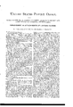
T. BROWN, Jr.
Lantern.
Patented May 24, 1864.
177115112 Mm} 7 w Wflmm JNITED STATES PATENT OFFICE.
THOMAS BROWN, JR, OF ALLEGHENY COUNTY, ASSIGNOR TO HIMSELF AND JAMES MCLAIN, OF PITTSBUR-G, PENNSYLVANIA.
IMPROVEMENT IN ATTACHMENTS OF LANTERN-GUARDS.
Specification forming part of Letters Patent No. 12,906, dated May 24, 1864.
To all whom it may concern:
Be it known that I, THOMAS BROWN, Jr., in the county of Allegheny and State of Pennsylvania, have invented a new and useful Improvement in Lanterns and I do hereby declare the following to be a full, clear, and
ence denote similar parts of the lantern.
The ordinary mode of attaching the glass or globe to lanterns is to insert the lower part of the glass into the lower portion or lamppiece of the lantern and cementthem together with plaster-of-paris, and to place the cap or top piece of the lantern on the top of the glass and unite them with cement in like manner. The wire guard or frame which surrounds the glass is soldered to the frame above and below. Notwithstanding the protection afforded by the wire guard, the glass often getsbroken, and cannot be replaced without sending the remaining parts to themanufacturer.
As large quantities of this description of lanterns are used, especially by railroad companies, it would be a great convenience, as well as a saving of expense, if the wire guard could be removed and the globe replaced without unsoldering and resoldering the guard or the use of cement for attaching the frame of the lantern to the glass.
To accomplish these objects is the purpose of my invention.
To enable others skilled in the art to construct and use my improved lantern, I will proceed to describe the construction and operation of my improvements.
In the drawings, a is the bottom part or lamp-piece of the lantern-frame, and b is the cap or top piece. 0 is the glass or globe, which maybe made of any desired shape. On the outer surface of the glass 0, at ashort distance (say one-fourth of an inch) above its lower edge, is a bead, d, surrounding the glass and projecting so far from its surface that the head will not enter the lamp-piece d, but rest upon its upper edge, as seen in Fig. 1. A similar head, 6, surrounds and projects from the outer surface of the glass near its upper edge, on which bead rests the lower edge of the cappiece I). No cement is used to fasten these parts together, as they are held in place by the wires f f of the guard. The guard consists of a number of wires, f f, which are looped at z to a flange, g, projecting from the cap. These guard-wires are curved outward in the usual shape, and have a kink at is, so as to receive and hold the wire hoop h, which surrounds the glass at a little distance from it, where the diameter of the glass is greatest. The wire hoop h is not fastened to the guardwires ff, as is ordinarily the case, but is held in place by the tension of the wires ff, which are drawn down outside of the hoop h and enter into kinks k at equal distances apart in the hoop h and fastened by a loop, 0, in the end of the wire and a pin at l to the bottom piece of the lantern. At the top of the lamppiece a is an apron, m, which surrounds itand extends outward, curving down so as to cover a circular slide, a. (Shown in Fig. 2.) Under the apron in, and attached to the upper part of the lamp-piece a, are two braces, 19, one on each side of the lantern. The circular slide a surrounds the brace 12 and slides upon or around it, so that thebraces p p and the outer edge of the apron m, which is turned under the outer edge of the circular slide a, sustain and hold in place the circular slide a, to which the lower extremity of the guard-wiresffis attached. The apron on has a number of notches, q q, cut in its outer edge at equal intervals apart, each of which re ceives the loop 0 of one of the guardwires ff. The circular slide extending to the edge of the apron covers these notches r r, &c., as seen in Fig. 2. The circular slide has also a SJIiCS of notches, r r, &c., to assist the loops 0 of the guard-wires f,- but these notches r r, &c., are not equidistant, but are so placed as that when one notch, q, in the apron coincides with a notch, r, in the slide the next notch, 1- in the slide will be just beyond the notch g in the apron, and the third notch r in the slide will be still further from the third notch g in the apron, and so on, each notch in the slide being farther from the notch in the apron, the degree of difference being the width of one of the notches, q or r, as seen in Fig. 2. From each notch r r, &c., in the slide a slot extends parallel to the circumference of the slide, thus forming a pin, 8, at each notch. These slots vary in length, the end of each slot farthest from its notch in the slide being equidistant from the similar point in the slot on each side of it. The object and effect of this construction of the slide and apron and the arrangement of the slots in both is to enable the guard-wiresff to be fastened to the apron m one after the other, because if they had all to be fastened at one time it would be impos sible for one person to attach the guard; but as one wire only can be fastened at a time they can be all taken in succession and be fastened with the greatest ease. The circular slide n has a button, t, projecting from its periphery at a point where the edge of the apron is cut away to allow of the slide being turned sufficiently to loosen or fasten all the wires. The button may, if preferred, be turned down so as to ai'oid liability to accidental movement.
The mode of attaching the guard-wires is as follows: The first notch 1' to the right of the button at in the slide being made to coincide with the first notch q in the apron, the loop 0 at the lower end of one of the guard wires f is inserted and the slide is moved slightly to the left, which causes the point of the pin 8 in the slide to enter the loop 0, thus securing it in place. This motion of the slide n to engage the loop 0 of the wiref brings the next notch, 1", in the slide to coincide with the notch q in the apron. (This is the position of the parts shown in Fig. 2.) The loop 0 of the next wire, f, is then inserted in the open notches q r, and the slide is turned a little farther to the left, which causes the pin 8 to enter the loop 0. This motion of the slide causes a correspondence between the next notches, g and T The next-wire is inserted, and so on, in succession, until all are fastened. The guard will then be drawn tightly down, and will thereby securely fasten the glass in place between the lam p-piecc a and cap I). The friction of the pins 8 s, 850., of the slide in the loops 0 of the guard-wires will prevent any tendency'of the slide to move or liability to accidental displacement. In case the glass should be broken it is only necessary in order to remove it to draw back the slide a by the button t, when each of the wires ff, &c., in succession will be released from the pins 8 s. &c., and the top piece I), with the wires ff, 85c, attached will be separated from the bottom piece I), and the hoop It will also be detached.
If preferred the'apron and slide may be attached to the top piece of the lantern, and the wires f f may be looped to the bottom piece; but the arrangement above described will be found the more convenient.
Having thus described my improvement in lanterns, what I claim as my invention, and desire to secure by Letters Patent, is-
1. The mode of attaching the globe or glass to the top and bottom pieces of the lantern without cement by means of the guard, substantially as hereinbefore described.
2. The use of a guard for lanterns composed of a detached hoop and wires looped either to the top or bottom part of the lantern and secured to the other part by means of a series of pins on a slide, or other equivalent device, constructed and arranged substantially as described.
3. The arrangement and combination of the notches in the lantern-frame and notches and pins in the slide in such a manner as to fasten the wires in succession.
In testimony whereof the said THOMAS BROWN, Jr., hath hereunto set his hand in presence of us.
THUMAS BROWN, JR. WVitnesscs:
A. S. NICHOLSON, J. WARD NICHOLSON.
Publications (1)
| Publication Number | Publication Date |
|---|---|
| US42906A true US42906A (en) | 1864-05-24 |
Family
ID=2112472
Family Applications (1)
| Application Number | Title | Priority Date | Filing Date |
|---|---|---|---|
| US42906D Expired - Lifetime US42906A (en) | Improvement in attachments of lantern-guards |
Country Status (1)
| Country | Link |
|---|---|
| US (1) | US42906A (en) |
-
0
- US US42906D patent/US42906A/en not_active Expired - Lifetime
Similar Documents
| Publication | Publication Date | Title |
|---|---|---|
| US42906A (en) | Improvement in attachments of lantern-guards | |
| US450510A (en) | Loop-button | |
| US1085857A (en) | Crown-guard for bracelet-watches. | |
| US1141494A (en) | Umbrella. | |
| US1435642A (en) | Mainspring arbor for timepieces | |
| US13286A (en) | Lantern | |
| US652245A (en) | Holder or guard for pocket-books. | |
| US190862A (en) | Improvement in neck-tie retainers | |
| US549099A (en) | Charles bergener | |
| US56604A (en) | Improvement in hand-lanterns | |
| US516332A (en) | Spool or bobbin holder | |
| US413981A (en) | Ring or bail for suspending or lifting vessels | |
| US400763A (en) | John s | |
| US841648A (en) | Lantern. | |
| US1199527A (en) | Combination lamp burner, chimney, and clamping device. | |
| US50653A (en) | Improvement in lantern-guards | |
| US1008836A (en) | Globe-holder for lamps. | |
| US959635A (en) | Lantern. | |
| US1055582A (en) | Hat-pin guard. | |
| US1058282A (en) | Lamp-chimney holder. | |
| US202684A (en) | Improvement in buttons | |
| US162090A (en) | Improvement in lanterns | |
| US570442A (en) | Key-ring or the like | |
| US418037A (en) | Tubular lantern | |
| US375020A (en) | stone |