US4290586A - Furnace and method with sensor - Google Patents
Furnace and method with sensor Download PDFInfo
- Publication number
- US4290586A US4290586A US06/118,479 US11847980A US4290586A US 4290586 A US4290586 A US 4290586A US 11847980 A US11847980 A US 11847980A US 4290586 A US4290586 A US 4290586A
- Authority
- US
- United States
- Prior art keywords
- atmosphere
- casing
- furnace
- platinum group
- group metal
- Prior art date
- Legal status (The legal status is an assumption and is not a legal conclusion. Google has not performed a legal analysis and makes no representation as to the accuracy of the status listed.)
- Expired - Lifetime
Links
- 238000000034 method Methods 0.000 title description 11
- BASFCYQUMIYNBI-UHFFFAOYSA-N platinum Chemical group [Pt] BASFCYQUMIYNBI-UHFFFAOYSA-N 0.000 claims abstract description 109
- 229910052751 metal Inorganic materials 0.000 claims abstract description 43
- 239000002184 metal Substances 0.000 claims abstract description 43
- 229910052760 oxygen Inorganic materials 0.000 claims abstract description 34
- 239000001301 oxygen Substances 0.000 claims abstract description 34
- QVGXLLKOCUKJST-UHFFFAOYSA-N atomic oxygen Chemical compound [O] QVGXLLKOCUKJST-UHFFFAOYSA-N 0.000 claims abstract description 33
- 239000007789 gas Substances 0.000 claims abstract description 32
- 239000003792 electrolyte Substances 0.000 claims abstract description 25
- 239000000356 contaminant Substances 0.000 claims abstract description 19
- 239000007787 solid Substances 0.000 claims abstract description 6
- 238000010438 heat treatment Methods 0.000 claims abstract description 5
- MCMNRKCIXSYSNV-UHFFFAOYSA-N Zirconium dioxide Chemical compound O=[Zr]=O MCMNRKCIXSYSNV-UHFFFAOYSA-N 0.000 claims description 13
- 239000000919 ceramic Substances 0.000 claims description 9
- 230000000694 effects Effects 0.000 claims description 7
- 238000005247 gettering Methods 0.000 claims description 5
- -1 magnesium aluminate Chemical class 0.000 claims description 4
- 229910052596 spinel Inorganic materials 0.000 claims description 3
- 239000011029 spinel Substances 0.000 claims description 3
- 229910002076 stabilized zirconia Inorganic materials 0.000 claims description 3
- 239000013078 crystal Substances 0.000 claims description 2
- 229910052749 magnesium Inorganic materials 0.000 claims description 2
- 239000011777 magnesium Substances 0.000 claims description 2
- 239000011214 refractory ceramic Substances 0.000 claims 1
- 238000005255 carburizing Methods 0.000 abstract description 7
- 229910052697 platinum Inorganic materials 0.000 description 42
- 238000000576 coating method Methods 0.000 description 13
- 239000011248 coating agent Substances 0.000 description 10
- 238000002485 combustion reaction Methods 0.000 description 9
- PNEYBMLMFCGWSK-UHFFFAOYSA-N aluminium oxide Inorganic materials [O-2].[O-2].[O-2].[Al+3].[Al+3] PNEYBMLMFCGWSK-UHFFFAOYSA-N 0.000 description 7
- 230000003197 catalytic effect Effects 0.000 description 7
- 239000004568 cement Substances 0.000 description 7
- 239000000203 mixture Substances 0.000 description 6
- 238000012544 monitoring process Methods 0.000 description 6
- 239000002574 poison Substances 0.000 description 6
- 231100000614 poison Toxicity 0.000 description 6
- 239000003054 catalyst Substances 0.000 description 5
- 230000006872 improvement Effects 0.000 description 5
- XEEYBQQBJWHFJM-UHFFFAOYSA-N Iron Chemical compound [Fe] XEEYBQQBJWHFJM-UHFFFAOYSA-N 0.000 description 4
- PXHVJJICTQNCMI-UHFFFAOYSA-N Nickel Chemical compound [Ni] PXHVJJICTQNCMI-UHFFFAOYSA-N 0.000 description 4
- HCHKCACWOHOZIP-UHFFFAOYSA-N Zinc Chemical compound [Zn] HCHKCACWOHOZIP-UHFFFAOYSA-N 0.000 description 4
- 238000005275 alloying Methods 0.000 description 4
- 239000010410 layer Substances 0.000 description 4
- 229910052725 zinc Inorganic materials 0.000 description 4
- 239000011701 zinc Substances 0.000 description 4
- 239000002253 acid Substances 0.000 description 3
- 239000011133 lead Substances 0.000 description 3
- WABPQHHGFIMREM-UHFFFAOYSA-N lead(0) Chemical compound [Pb] WABPQHHGFIMREM-UHFFFAOYSA-N 0.000 description 3
- 239000002245 particle Substances 0.000 description 3
- 230000001681 protective effect Effects 0.000 description 3
- 239000007784 solid electrolyte Substances 0.000 description 3
- 229910001233 yttria-stabilized zirconia Inorganic materials 0.000 description 3
- RYGMFSIKBFXOCR-UHFFFAOYSA-N Copper Chemical compound [Cu] RYGMFSIKBFXOCR-UHFFFAOYSA-N 0.000 description 2
- KDLHZDBZIXYQEI-UHFFFAOYSA-N Palladium Chemical compound [Pd] KDLHZDBZIXYQEI-UHFFFAOYSA-N 0.000 description 2
- VYPSYNLAJGMNEJ-UHFFFAOYSA-N Silicium dioxide Chemical compound O=[Si]=O VYPSYNLAJGMNEJ-UHFFFAOYSA-N 0.000 description 2
- 229910000831 Steel Inorganic materials 0.000 description 2
- 230000002411 adverse Effects 0.000 description 2
- 229910045601 alloy Inorganic materials 0.000 description 2
- 239000000956 alloy Substances 0.000 description 2
- 230000008859 change Effects 0.000 description 2
- 238000006243 chemical reaction Methods 0.000 description 2
- 229910052802 copper Inorganic materials 0.000 description 2
- 239000010949 copper Substances 0.000 description 2
- 239000000835 fiber Substances 0.000 description 2
- 210000004905 finger nail Anatomy 0.000 description 2
- 238000010304 firing Methods 0.000 description 2
- 229910052742 iron Inorganic materials 0.000 description 2
- 150000002739 metals Chemical class 0.000 description 2
- 229910052759 nickel Inorganic materials 0.000 description 2
- 239000000843 powder Substances 0.000 description 2
- 230000008569 process Effects 0.000 description 2
- 239000010935 stainless steel Substances 0.000 description 2
- 229910001220 stainless steel Inorganic materials 0.000 description 2
- 239000010959 steel Substances 0.000 description 2
- 238000011144 upstream manufacturing Methods 0.000 description 2
- ZOXJGFHDIHLPTG-UHFFFAOYSA-N Boron Chemical compound [B] ZOXJGFHDIHLPTG-UHFFFAOYSA-N 0.000 description 1
- VYZAMTAEIAYCRO-UHFFFAOYSA-N Chromium Chemical compound [Cr] VYZAMTAEIAYCRO-UHFFFAOYSA-N 0.000 description 1
- MYMOFIZGZYHOMD-UHFFFAOYSA-N Dioxygen Chemical compound O=O MYMOFIZGZYHOMD-UHFFFAOYSA-N 0.000 description 1
- DGAQECJNVWCQMB-PUAWFVPOSA-M Ilexoside XXIX Chemical compound C[C@@H]1CC[C@@]2(CC[C@@]3(C(=CC[C@H]4[C@]3(CC[C@@H]5[C@@]4(CC[C@@H](C5(C)C)OS(=O)(=O)[O-])C)C)[C@@H]2[C@]1(C)O)C)C(=O)O[C@H]6[C@@H]([C@H]([C@@H]([C@H](O6)CO)O)O)O.[Na+] DGAQECJNVWCQMB-PUAWFVPOSA-M 0.000 description 1
- PWHULOQIROXLJO-UHFFFAOYSA-N Manganese Chemical compound [Mn] PWHULOQIROXLJO-UHFFFAOYSA-N 0.000 description 1
- OAICVXFJPJFONN-UHFFFAOYSA-N Phosphorus Chemical compound [P] OAICVXFJPJFONN-UHFFFAOYSA-N 0.000 description 1
- KJTLSVCANCCWHF-UHFFFAOYSA-N Ruthenium Chemical compound [Ru] KJTLSVCANCCWHF-UHFFFAOYSA-N 0.000 description 1
- XUIMIQQOPSSXEZ-UHFFFAOYSA-N Silicon Chemical compound [Si] XUIMIQQOPSSXEZ-UHFFFAOYSA-N 0.000 description 1
- BQCADISMDOOEFD-UHFFFAOYSA-N Silver Chemical compound [Ag] BQCADISMDOOEFD-UHFFFAOYSA-N 0.000 description 1
- NINIDFKCEFEMDL-UHFFFAOYSA-N Sulfur Chemical compound [S] NINIDFKCEFEMDL-UHFFFAOYSA-N 0.000 description 1
- RTAQQCXQSZGOHL-UHFFFAOYSA-N Titanium Chemical compound [Ti] RTAQQCXQSZGOHL-UHFFFAOYSA-N 0.000 description 1
- 238000005299 abrasion Methods 0.000 description 1
- 230000009471 action Effects 0.000 description 1
- 229910052787 antimony Inorganic materials 0.000 description 1
- WATWJIUSRGPENY-UHFFFAOYSA-N antimony atom Chemical compound [Sb] WATWJIUSRGPENY-UHFFFAOYSA-N 0.000 description 1
- 239000007864 aqueous solution Substances 0.000 description 1
- 229910052785 arsenic Inorganic materials 0.000 description 1
- RQNWIZPPADIBDY-UHFFFAOYSA-N arsenic atom Chemical compound [As] RQNWIZPPADIBDY-UHFFFAOYSA-N 0.000 description 1
- 230000015572 biosynthetic process Effects 0.000 description 1
- 229910052797 bismuth Inorganic materials 0.000 description 1
- JCXGWMGPZLAOME-UHFFFAOYSA-N bismuth atom Chemical compound [Bi] JCXGWMGPZLAOME-UHFFFAOYSA-N 0.000 description 1
- 229910052796 boron Inorganic materials 0.000 description 1
- 229910052804 chromium Inorganic materials 0.000 description 1
- 239000011651 chromium Substances 0.000 description 1
- 230000001427 coherent effect Effects 0.000 description 1
- 230000000052 comparative effect Effects 0.000 description 1
- 230000000295 complement effect Effects 0.000 description 1
- 239000000470 constituent Substances 0.000 description 1
- 238000007796 conventional method Methods 0.000 description 1
- 238000005336 cracking Methods 0.000 description 1
- 238000002242 deionisation method Methods 0.000 description 1
- 229910001882 dioxygen Inorganic materials 0.000 description 1
- 238000007598 dipping method Methods 0.000 description 1
- 239000000428 dust Substances 0.000 description 1
- 239000010408 film Substances 0.000 description 1
- 239000003546 flue gas Substances 0.000 description 1
- 239000000446 fuel Substances 0.000 description 1
- PCHJSUWPFVWCPO-UHFFFAOYSA-N gold Chemical compound [Au] PCHJSUWPFVWCPO-UHFFFAOYSA-N 0.000 description 1
- 229910052737 gold Inorganic materials 0.000 description 1
- 239000010931 gold Substances 0.000 description 1
- 150000002366 halogen compounds Chemical class 0.000 description 1
- 229910001385 heavy metal Inorganic materials 0.000 description 1
- 229910001026 inconel Inorganic materials 0.000 description 1
- 230000002452 interceptive effect Effects 0.000 description 1
- 238000005304 joining Methods 0.000 description 1
- 239000000171 lavandula angustifolia l. flower oil Substances 0.000 description 1
- 238000011068 loading method Methods 0.000 description 1
- 229910052748 manganese Inorganic materials 0.000 description 1
- 239000011572 manganese Substances 0.000 description 1
- 238000000465 moulding Methods 0.000 description 1
- 229910000480 nickel oxide Inorganic materials 0.000 description 1
- 229910052755 nonmetal Inorganic materials 0.000 description 1
- 150000002843 nonmetals Chemical class 0.000 description 1
- 230000003647 oxidation Effects 0.000 description 1
- 238000007254 oxidation reaction Methods 0.000 description 1
- GNRSAWUEBMWBQH-UHFFFAOYSA-N oxonickel Chemical compound [Ni]=O GNRSAWUEBMWBQH-UHFFFAOYSA-N 0.000 description 1
- 239000003973 paint Substances 0.000 description 1
- 229910052763 palladium Inorganic materials 0.000 description 1
- 239000008188 pellet Substances 0.000 description 1
- 229910052698 phosphorus Inorganic materials 0.000 description 1
- 239000011574 phosphorus Substances 0.000 description 1
- 239000011148 porous material Substances 0.000 description 1
- 239000011253 protective coating Substances 0.000 description 1
- 239000011241 protective layer Substances 0.000 description 1
- 239000011819 refractory material Substances 0.000 description 1
- 238000003303 reheating Methods 0.000 description 1
- 229910052707 ruthenium Inorganic materials 0.000 description 1
- 238000007790 scraping Methods 0.000 description 1
- 230000035939 shock Effects 0.000 description 1
- 229910052710 silicon Inorganic materials 0.000 description 1
- 239000010703 silicon Substances 0.000 description 1
- 235000012239 silicon dioxide Nutrition 0.000 description 1
- 239000000377 silicon dioxide Substances 0.000 description 1
- 229910052709 silver Inorganic materials 0.000 description 1
- 239000004332 silver Substances 0.000 description 1
- 238000005245 sintering Methods 0.000 description 1
- 239000000779 smoke Substances 0.000 description 1
- 229910052708 sodium Inorganic materials 0.000 description 1
- 239000011734 sodium Substances 0.000 description 1
- 239000000243 solution Substances 0.000 description 1
- 239000003381 stabilizer Substances 0.000 description 1
- 239000000126 substance Substances 0.000 description 1
- 229910052717 sulfur Inorganic materials 0.000 description 1
- 239000011593 sulfur Substances 0.000 description 1
- 230000001502 supplementing effect Effects 0.000 description 1
- 230000004083 survival effect Effects 0.000 description 1
- 239000010936 titanium Substances 0.000 description 1
- 229910052719 titanium Inorganic materials 0.000 description 1
- RUDFQVOCFDJEEF-UHFFFAOYSA-N yttrium(III) oxide Inorganic materials [O-2].[O-2].[O-2].[Y+3].[Y+3] RUDFQVOCFDJEEF-UHFFFAOYSA-N 0.000 description 1
Images
Classifications
-
- F—MECHANICAL ENGINEERING; LIGHTING; HEATING; WEAPONS; BLASTING
- F27—FURNACES; KILNS; OVENS; RETORTS
- F27D—DETAILS OR ACCESSORIES OF FURNACES, KILNS, OVENS, OR RETORTS, IN SO FAR AS THEY ARE OF KINDS OCCURRING IN MORE THAN ONE KIND OF FURNACE
- F27D21/00—Arrangements of monitoring devices; Arrangements of safety devices
-
- F—MECHANICAL ENGINEERING; LIGHTING; HEATING; WEAPONS; BLASTING
- F27—FURNACES; KILNS; OVENS; RETORTS
- F27B—FURNACES, KILNS, OVENS, OR RETORTS IN GENERAL; OPEN SINTERING OR LIKE APPARATUS
- F27B17/00—Furnaces of a kind not covered by any preceding group
- F27B17/0016—Chamber type furnaces
-
- F—MECHANICAL ENGINEERING; LIGHTING; HEATING; WEAPONS; BLASTING
- F27—FURNACES; KILNS; OVENS; RETORTS
- F27D—DETAILS OR ACCESSORIES OF FURNACES, KILNS, OVENS, OR RETORTS, IN SO FAR AS THEY ARE OF KINDS OCCURRING IN MORE THAN ONE KIND OF FURNACE
- F27D19/00—Arrangements of controlling devices
- F27D2019/0006—Monitoring the characteristics (composition, quantities, temperature, pressure) of at least one of the gases of the kiln atmosphere and using it as a controlling value
- F27D2019/0012—Monitoring the composition of the atmosphere or of one of their components
Definitions
- This invention relates to an improvement in the use of the known type of oxygen sensor comprising a solid oxygen-ion-conducting electrolyte with porous, thin layer or film, metal (e.g. platinum) electrodes attached on substantially opposite surfaces of the electrolyte.
- metal e.g. platinum
- This type of sensor has been known for use in monitoring: (1) exhaust gases of internal combustion engines in thermodynamic nonequilibrium for control of the air-fuel ratio in the combustion process, (2) stack or flue gases of industrial combustion furnaces for control of the combustion process to eliminate smoke and other undesirable emissions, and (3) furnace atmospheres of metal heat treating and other furnaces in substantial thermodynamic equilibrium for control of their oxygen potential, e.g. in nonoxidizing and reducing gas atmospheres.
- U.S. Pat. No. 4,021,326 notes the problem of catalytic poisons which interfere with the catalytic activity of the catalytic (e.g. platinum) film electrode. Such activity is needed to catalyze the formation of thermodynamically stable gases (i.e. gases in thermodynamic equilibrium) from the nonequilibrium exhaust gases prior to contacting the electrolyte with such stable gases.
- the remedy suggested by this patent for such poison problem is the application of a getter for the catalytic poisons in or on top of the thin, porous, protective layer covering the catalytic film electrode.
- Identified poisons are heavy metals such as lead, copper, zinc, and nonmetals such as sulfur and halogen compounds.
- Suitable getters for these poisons are noted to be gold, silver, nickel and/or nickel oxide and silicon dioxide. It is to be noted, however, that catalyst poisons are not conceptually nor quantitatively the same as embrittling alloy contaminants of an electrode as noted in U.S. Pat. No. 3,645,875.
- U.S. Pat. No. 4,121,989 shows a specially tailored oxygen sensor device for greater efficiency, accuracy and reproducible operation in monitoring stack gases from industrial combustion furnaces to control the degree of combustion and combustion efficiency with excess air.
- Such device has felted ceramic fiber discs partly embedded into fired, thin-layer, paste-derived, platinum electrodes and thermally reduced, high surface area, platinum particles dispersed over the electrode surfaces and within the felted discs as a result of applying chloroplatinic acid through the felted discs to the electrode surfaces. Such particles augment the capacity of the platinum electrodes to effect the ionization-deionization reactions of oxygen in the device.
- platinum group metal e.g. platinum
- platinum group metal can and should be employed as a getter of contaminants of such metal (especially zinc contaminant) in nonoxidizing and reducing gas atmospheres of metal heat treating furnaces, when positioned upstream from an oxygen sensor, to protect the film electrode of the sensor made of the same platinum group metal as in the getter and that is to contact such atmosphere for determining and monitoring the oxygen potential of that atmosphere.
- Our platinum group metal getter significantly extends the life of the oxygen sensor by reacting and alloying with the platinum group metal contaminants and thus removing them from the gas atmosphere stream before those contaminants can damage the film electrode of the same platinum group metal contacted by such stream.
- our invention is a furnace for heat treatment of metal workpieces in nonoxidizing (or reducing) gas atmosphere containing platinum group metal contaminants.
- the furnace comprises:
- an enclosure defining a chamber adapted to contain the workpieces and the atmosphere, the enclosure including at least one wall portion having an oxygen sensor device extending therethrough to monitor the oxygen potential of the atmosphere,
- the sensor device comprising a casing with one portion thereof mounted in an opening in the wall portion and a second portion of the casing protruding into the chamber,
- the casing having an inlet in the second portion for the atmosphere to continuously enter and flow within the casing from the chamber,
- an oxygen sensor mounted within the casing with an electroded portion of the sensor intermediate of the inlet and the one portion of the casing,
- the electroded portion comprising a solid oxygen-ion-conducting electrolyte and a film electrode of platinum group metal attached on a surface of the electrolyte arranged to contact the atmosphere flowing within the casing, and
- a platinum group metal contaminant getter consisting essentially of the same platinum group metal as in the electrode and arranged in the casing between the inlet and the electroded portion so that the atmosphere passes into contact therewith to effect gettering of the platinum group metal contaminants from the atmosphere.
- our invention is a method of heat treating metal workpieces in a nonoxidizing (or reducing) gas atmosphere containing platinum group metal contaminants.
- the method comprises:
- an oxygen sensor comprising a solid oxygen-ion-conducting electrolyte with a film electrode of the same platinum group metal as in the getter and attached on a surface of the electrolyte and exposed to those portions whereby the oxygen potential of the atmosphere is monitored for undesirable change in that potential.
- the invention also includes our recognition and discovery of a particularly advantageous form for employing platinum group metal as the getter in such heat treating furnace and its operation. That form provides reasonably extended durability and gettering efficiency for the getter without interfering with the capability of the oxygen sensor device to properly monitor the furnace atmosphere for its oxygen potential.
- the form comprises a thin-walled, multipassaged honeycomb body (preferably of porous ceramic) through whose plurality of passages the furnace atmosphere flows to the oxygen sensor and on (and preferably also within) whose walls the platinum getter is contained and exposed to the atmosphere.
- FIG. 1 is a partially sectioned view of a portion of a heat treating furnace enclosure or wall through which is mounted an oxygen sensor device of the present invention
- FIG. 2 is a sectional view taken along a line 2--2 in FIG. 1.
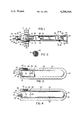
- FIG. 3 is an enlarged sectional view of one variation of an oxygen sensor useful in the present invention.
- FIG. 4 is an enlarged sectional view of another variation of an oxygen sensor useful in the present invention.
- furnace wall 7 defines (in part) the furnace chamber space to the right of such wall.
- a collar member 9 mounted in an opening in the wall 7, as by welded joint 8, is a collar member 9, whose inner annular surface is threaded in a complementary manner to receive the threads 17 on the larger end portion 16 of the fitting 14 for mounting the oxygen sensor device in and through the wall 7.
- the oxygen sensor device comprises an oxygen-ion-conducting solid electrolyte tube 10 positioned inside a protective casing 12.
- the solid electrolyte is a yttria-stabilized zirconia containing about 8% Y 2 O 3 by weight
- casing 12 is made of Inconel alloy.
- any solid oxygen-ion-conducting electrolyte and any suitable heat-resistance metal of the casing can be used.
- One end of casing 12 is positioned inside the larger bore of fitting 14 so as to fully extend into that bore passing through larger end portion 16 and partly into the hexagonal-shaped middle portion 15 of fitting 14.
- Screws 13 and fitting 14 are preferably made of stainless steel.
- Fitting 14 includes a smaller end portion 18 with threads 19 for connection to a terminal structure such as a conventional thermocouple head (not shown). Smaller end portion 18 also has a bore centrally within which the open end of electrolyte tube 10 is fastened by means of a suitable cement 20, such as sauereisen cement.
- the closed end of electrolyte tube 10 has an outer platinum film electrode 22 extending over the entire hemispherical end of the tube and on up the tube a short distance to the edge 23 of electrode 22.
- An inner platinum film electrode (not shown) extends over the portion of the inner bore surface of the tube 10 opposite to that of the outer surface covered by electrode 22 (as is conventional).
- the platinum film electrodes can be formed by any suitable method, but it is preferred to use a platinum paste which is painted on the desired surfaces and then fired thereon to partially sinter the resulting platinum coating.
- a particularly desired paste mixture comprises equal parts by weight of platinum resinate paste containing 65.5 wt. % Pt and platinum dust or powder of -325 mesh U.S.
- Standard Screen and to 85 parts by weight of which is added 15 parts by weight of lavender oil for providing a paint consistency to the paste mixture.
- This mixture is applied to a cleaned electrolyte tube surface, dried at about 120° C. for 15 minutes and then fired at about 1150° C. for one hour. This procedure is used for each coating application and usually three coating applications, one on top of the other, are necessary for an adequate thickness of platinum to form the film electrodes.
- the second and subsequent coatings are usually fired at about 1000° C. for one hour.
- an outer platinum electrical lead wire 24 is connected to outer electrode 22 and an inner platinum electrical lead wire 26 is connected to the inner electrode (not shown).
- wires can be of 12-17 mil diameter sizes.
- Wire 24 is carried within a single-bore alumina tube 28 extending through casing 12 and fitting 14 to the left end of portion 18.
- Such tube 28 is also fastened within the bore of portion 18 by means of the cement 20.
- alumina sleeves 30, 31 are cemented to tube 10 as shown in FIGS. 1-3 and the tube 28 is slidably held within the bore of sleeves 30, 31.
- tube 28 electrically insulates and physically protects wire 24 without causing any differential thermal expansion stresses in the sensor device.
- a platinum connector wire 32 (see FIGS. 2 and 3) is fixed to electrode 22 and spot welded to wire 24 at their overlap junction 33.
- Wire 32 is preferably thicker than wire 24, e.g. 17-40 mil diameter. In connecting wire 32 to electrode 22, only one fired paste mixture coating is made prior to placing wire 32 on that coating.
- Wire 32 can be placed on the initial electrode coating in any desired manner, e.g. by coiling a portion 34 around the electrode coating 22 as in FIG. 3 or by molding a portion 34' to extend longitudinally along electrode coating 22 and around its hemispherical end with curved portion 35 of wire 32 as in FIG. 4.
- Inner lead wire 26 is carried in a single-bore alumina tube 36 from adjacent the inside hemispherical closed end surface of tube 10 (where a small protruding portion of wire 26 is fastened to the inner electrode by any suitable or conventional means) on through the bore of tube 10 to the opposite end thereof.
- thermocouple wires 38, 39 carried in a double-bore alumina tube 40 and a tube 42 for a reference oxygen gas (e.g. air). These components extend into the bore of tube 10 to a point shortly beyond electrode edge 23 (i.e. between edge 23 and the hemispherical closed end of tube 10). It is in the vicinity of that point at which the thermocouple wires protrude out of tube 40 and are joined in a thermocouple junction and also the reference gas is introduced to the inner electrode from the open end of tube 42.
- a reference oxygen gas e.g. air
- these components also extend oppositely to the other end of tube 10, where further extensions of wires 38, 39 and tube 42 as well as of wires 24, 26 are available for respective appropriate connections to a thermocouple temperature measuring circuit, a gas supply and a voltage measuring circuit, all as is conventional.
- a thermocouple temperature measuring circuit e.g., a thermocouple temperature measuring circuit
- a gas supply and a voltage measuring circuit e.g., a thermocouple temperature measuring circuit
- the main improvement element 50 of the present invention is preferably embodied in an assembly having a porous ceramic boot 44, as claimed in the aforesaid copending application Ser. No. 118,480. It is advantageous to slidably and frictionally engage the compressible, porous, ceramic boot or cover 44 and its hemispherically closed end 45 onto and over electrode 22 and wire 32 to physically hold the electrode 22 and wire 32 in contact with electrolyte 10 even if the platinum of electrode 22 and wire 32 becomes embrittled after an extended period of service and would otherwise tend to separate from contact with the electrolyte tube 10.
- Boot 44 is made of a sintered, porous, oxide that is thermodynamically stable in the nonoxidizing or reducing atmosphere of the heat treating furnace and is nonreactive with platinum.
- such oxide is zirconia which is advantageously in a stabilized form with a stabilizer that is also nonreactive with platinum.
- it is yttria-stabilized zirconia with 8 wt. % Y 2 O 3 .
- the boot 44 should have an open porosity of greater than 50 volume % (preferably greater than 80 volume %) for adequate rapid passage of monitored atmosphere to the electrode 22.
- boot 44 is composed of a sintered mass of short 8 wt. % yttria-stabilized zirconia fibers (e.g. 1/16 inch mean length and 4-6 microns diameter) mixed with a minor portion (about 1 wt.
- Such mixture is shaped as a boot 44 and fired sufficiently to render the sintered boot to be a coherent, substantially firm structure with over 80 vol. % open porosity and yet capable of being grooved or compressed with the manual pressure of a person's fingernail.
- boot 44 can be slidably and firmly pressfit onto tube 10 over electrode 22 and wire 32 whereby the sliding engagement with wire 32 easily grooves or compresses an inner portion of boot 44 just sufficient to accomodate wire 32 therein without otherwise damaging boot 44. It is also advantageous for the boot 44 to extend over the tip of sleeve 31 so as to protect the portion of wire 32 entering sleeve 31.
- sleeve 31 is easily accomodated by sleeve 31 further grooving or compressing the inside of portion 46 of boot 44 just sufficient to accomodate sleeve 31, again without otherwise damaging boot 44.
- wire coil 34 FIG. 3
- it compresses the inner diameter 47 of boot 44 to an enlarged size just sufficient to accomodate coil 34.
- a getter 50 upstream from the electroded portion of tube 10. we include a honeycomb getter 50 positioned within the portion of casing 12 having a bore 48 of enlarged diameter relative to the remainder of casing 12 whereby the getter 50 is further positioned by shoulder 49 joining the two bore diameters of casing 12.
- Getter 50 comprises a thinwalled honeycomb body with a plurality of passages therethrough for passage of furnace atmosphere to the electroded portion of the oxygen sensor within boot 44.
- honeycomb body is known to cause relatively little back-pressure effect against incoming gases thereto, and that minor effect is easily overcome by the positive (i.e. greater than atmospheric) pressure and/or velocities of gas atmosphere flowing in a furnace chamber and entering the getter 50.
- the honeycomb getter 50 comprises a ceramic honeycomb body with porous walls containing platinum thereon and desirably within the open pores in the walls.
- Such honeycomb body can be made by any suitable or known method, such as those described in U.S. Pat. Nos.
- the preferred zirconia/spinel weight % ratios range from 65/35 to 30/70, with 60/40 being most preferred.
- the platinum can be applied to the walls of the honeycomb body in any suitable or known manner. Generally one can employ the conventional technique of impregnating the porous honeycomb body by dipping it in chloroplatinic acid (usually in an aqueous solution of 25 wt. % H 2 PtCl 6 ), draining excess solution from gas atmosphere to thermally decompose and reduce the acid to platinum metal residue on the honeycomb body. This dip/fire procedure is repeated about three to four times or so as to obtain a platinum loading of at least about 5 wt. % (and preferably about 10 wt. %) of the platinized honeycomb body. Such platinized honeycomb body with a 2 inch length and a 7/8 inch diameter has been found quite adequate to provide getter protection for an electroded portion of an electrolyte having a 2 inch length and a 3/8" outside diameter.
- the honeycomb getter 50 is a consumable element easily replaced as needed to provide adequate gettering for continued or extended life of the sensor device.
- casing 12 may include a protective extension 52 having a cap 53 threaded onto and closing its end opening, but also having side ports 54 for entrance of furnace atmosphere into casing 12.
- the extension 52 is omitted and end the casing 12 at the entrance (right) end of getter 50 with such casing end being open to the furnace atmosphere as an inlet therein.
- An optional outlet in the casing can be suitably provided and arranged at any point to the left of boot 44 (i.e. the electroded portion of tube 10) for exiting monitored atmosphere either within or outside of the furnace enclosure 7, e.g. by leaving an opening or passage through cement 20 within fitting portion 18 whereby the monitored furnace atmosphere passes completely through the casing 12 and fitting 14 to be suitably exited outside the furnace enclosure 7.
- the strong swirling action of the carburizing furnace atmosphere apparently causes turbulent flow in portions of such atmosphere in casing 12 so as to push them into contact with the electroded portion and then flush them back out of the inlet in order to allow new sequential portions to be pushed into casing 10 for contact with the electroded portion.
- the method of using the above-described sensor involves the heat treatment of metal workpieces in the chamber to the right of wall 7, into which the sensor device protrudes.
- Sequential portions of nonoxidizing or reducing furnace atmosphere enter the inlet at the right end of casing 12, e.g. the ports 54, and pass through getter 50.
- the portions After removal of platinum contaminants from those portions of atmosphere by getter 50, the portions continue to flow to and through boot 44 into contact with the electroded portion of electrolyte tube 10 containing electrode 22, wherein the oxygen potential of such atmosphere portions are detected and monitored by the oxygen sensor. Thereafter, such atmosphere portions are flushed out of the casing 12.
- air as a preferred reference gas is flowed into the left end of tube 42, through that tube and into the closed end of the bore within tube 10 where the inner platinum film electrode is located. Thereafter, the air reference gas passes through the bore of tube 10 to exit from its partially open left end.
Abstract
Description
Claims (5)
Priority Applications (2)
| Application Number | Priority Date | Filing Date | Title |
|---|---|---|---|
| US06/118,479 US4290586A (en) | 1980-02-04 | 1980-02-04 | Furnace and method with sensor |
| US06/251,535 US4362580A (en) | 1980-02-04 | 1981-04-06 | Furnace and method with sensor |
Applications Claiming Priority (1)
| Application Number | Priority Date | Filing Date | Title |
|---|---|---|---|
| US06/118,479 US4290586A (en) | 1980-02-04 | 1980-02-04 | Furnace and method with sensor |
Related Child Applications (1)
| Application Number | Title | Priority Date | Filing Date |
|---|---|---|---|
| US06/251,535 Division US4362580A (en) | 1980-02-04 | 1981-04-06 | Furnace and method with sensor |
Publications (1)
| Publication Number | Publication Date |
|---|---|
| US4290586A true US4290586A (en) | 1981-09-22 |
Family
ID=22378859
Family Applications (1)
| Application Number | Title | Priority Date | Filing Date |
|---|---|---|---|
| US06/118,479 Expired - Lifetime US4290586A (en) | 1980-02-04 | 1980-02-04 | Furnace and method with sensor |
Country Status (1)
| Country | Link |
|---|---|
| US (1) | US4290586A (en) |
Cited By (12)
| Publication number | Priority date | Publication date | Assignee | Title |
|---|---|---|---|---|
| US4479866A (en) * | 1980-10-17 | 1984-10-30 | Nissan Motor Company, Limited | Gas sensor with sensitive element enclosed in perforated hood |
| US4588493A (en) * | 1984-09-17 | 1986-05-13 | Blumenthal Robert N | Hot gas measuring probe |
| US4814061A (en) * | 1987-12-03 | 1989-03-21 | Blumenthal Robert N | Hot gas measuring probe |
| US4931851A (en) * | 1986-03-12 | 1990-06-05 | Thorn Emi Plc | Gas sensitive device |
| US4966348A (en) * | 1989-06-30 | 1990-10-30 | Lindberg Corp. | Method and apparatus for monitoring atmosphere in furnaces |
| US5324415A (en) * | 1989-06-09 | 1994-06-28 | Blumenthal Robert N | Apparatus and systems for analyzing a sample of treatment atmosphere having a carbon potential |
| US5851369A (en) * | 1996-09-20 | 1998-12-22 | Marathon Monitors, Inc. | Electrolytic sensor providing controlled burn-off of deposits on the electrodes |
| US20030084728A1 (en) * | 2001-11-06 | 2003-05-08 | Boltz Eric S. | Modular electrolytic sensor |
| US20030084706A1 (en) * | 2001-06-11 | 2003-05-08 | Boltz Eric S. | Sensor |
| US20080118393A1 (en) * | 2006-10-13 | 2008-05-22 | Anders Oskarsson | High strength and sagging resistant fin material |
| US7603793B2 (en) * | 2006-02-24 | 2009-10-20 | Ibeden Co., Ltd. | End-face heating apparatus, end-face drying method for honeycomb aggregated body, and method for manufacturing honeycomb structured body |
| US20090320888A1 (en) * | 2008-06-25 | 2009-12-31 | Boltz Eric S | Multi-port probe purge systems and techniques |
Citations (10)
| Publication number | Priority date | Publication date | Assignee | Title |
|---|---|---|---|---|
| US3645875A (en) * | 1967-11-23 | 1972-02-29 | Kent Ltd G | Electrode assembly |
| US3935089A (en) * | 1973-07-24 | 1976-01-27 | Nissan Motor Company Limited | Oxygen sensor coated with catalytic material |
| US3978006A (en) * | 1972-02-10 | 1976-08-31 | Robert Bosch G.M.B.H. | Methods for producing oxygen-sensing element, particularly for use with internal combustion engine exhaust emission analysis |
| US4021326A (en) * | 1972-06-02 | 1977-05-03 | Robert Bosch G.M.B.H. | Electro-chemical sensor |
| US4097353A (en) * | 1975-06-10 | 1978-06-27 | Nissan Motor Company, Limited | Article and method of forming porous coating on electrode layer of concentration cell type oxygen sensor |
| US4121989A (en) * | 1977-03-07 | 1978-10-24 | Uop Inc. | Method of making oxygen sensor |
| US4132615A (en) * | 1974-04-05 | 1979-01-02 | Robert Bosch Gmbh | Internal combustion engine exhaust gas oxygen sensor and catalyzer combination |
| US4140611A (en) * | 1977-07-25 | 1979-02-20 | Toyota Jidosha Kogyo Kabushiki Kaisha | Oxygen sensor |
| US4164462A (en) * | 1976-11-29 | 1979-08-14 | Hitachi, Ltd. | Oxygen sensor |
| US4240890A (en) * | 1976-10-29 | 1980-12-23 | Ngk Insulators, Ltd. | Oxygen partial pressure measuring device suitably adapted for internal combustion engine exhaust gases |
-
1980
- 1980-02-04 US US06/118,479 patent/US4290586A/en not_active Expired - Lifetime
Patent Citations (10)
| Publication number | Priority date | Publication date | Assignee | Title |
|---|---|---|---|---|
| US3645875A (en) * | 1967-11-23 | 1972-02-29 | Kent Ltd G | Electrode assembly |
| US3978006A (en) * | 1972-02-10 | 1976-08-31 | Robert Bosch G.M.B.H. | Methods for producing oxygen-sensing element, particularly for use with internal combustion engine exhaust emission analysis |
| US4021326A (en) * | 1972-06-02 | 1977-05-03 | Robert Bosch G.M.B.H. | Electro-chemical sensor |
| US3935089A (en) * | 1973-07-24 | 1976-01-27 | Nissan Motor Company Limited | Oxygen sensor coated with catalytic material |
| US4132615A (en) * | 1974-04-05 | 1979-01-02 | Robert Bosch Gmbh | Internal combustion engine exhaust gas oxygen sensor and catalyzer combination |
| US4097353A (en) * | 1975-06-10 | 1978-06-27 | Nissan Motor Company, Limited | Article and method of forming porous coating on electrode layer of concentration cell type oxygen sensor |
| US4240890A (en) * | 1976-10-29 | 1980-12-23 | Ngk Insulators, Ltd. | Oxygen partial pressure measuring device suitably adapted for internal combustion engine exhaust gases |
| US4164462A (en) * | 1976-11-29 | 1979-08-14 | Hitachi, Ltd. | Oxygen sensor |
| US4121989A (en) * | 1977-03-07 | 1978-10-24 | Uop Inc. | Method of making oxygen sensor |
| US4140611A (en) * | 1977-07-25 | 1979-02-20 | Toyota Jidosha Kogyo Kabushiki Kaisha | Oxygen sensor |
Non-Patent Citations (3)
| Title |
|---|
| Metals Handbook, 8th Edition, vol. 1, pp. 1178-1190 published 1961 by American Society for Metals. * |
| R. G. H. Record, reprint from Instrument Practice, Mar. 1970, published in Great Britian. * |
| R. G. H. Record, reprint from Metallurgia and Metal Forming, Dec. 1972/Jan. 1973, published in Great Britian. * |
Cited By (18)
| Publication number | Priority date | Publication date | Assignee | Title |
|---|---|---|---|---|
| US4479866A (en) * | 1980-10-17 | 1984-10-30 | Nissan Motor Company, Limited | Gas sensor with sensitive element enclosed in perforated hood |
| US4588493A (en) * | 1984-09-17 | 1986-05-13 | Blumenthal Robert N | Hot gas measuring probe |
| US4931851A (en) * | 1986-03-12 | 1990-06-05 | Thorn Emi Plc | Gas sensitive device |
| US4814061A (en) * | 1987-12-03 | 1989-03-21 | Blumenthal Robert N | Hot gas measuring probe |
| US5324415A (en) * | 1989-06-09 | 1994-06-28 | Blumenthal Robert N | Apparatus and systems for analyzing a sample of treatment atmosphere having a carbon potential |
| US5556556A (en) * | 1989-06-09 | 1996-09-17 | Blumenthal; Robert N. | Method for producing endothermic atmospheres and non-catalytic probe therefor |
| US4966348A (en) * | 1989-06-30 | 1990-10-30 | Lindberg Corp. | Method and apparatus for monitoring atmosphere in furnaces |
| US5851369A (en) * | 1996-09-20 | 1998-12-22 | Marathon Monitors, Inc. | Electrolytic sensor providing controlled burn-off of deposits on the electrodes |
| US6752002B2 (en) | 2001-06-11 | 2004-06-22 | Marathon Sensors, Inc. | Sensor |
| US20030084706A1 (en) * | 2001-06-11 | 2003-05-08 | Boltz Eric S. | Sensor |
| US20030084728A1 (en) * | 2001-11-06 | 2003-05-08 | Boltz Eric S. | Modular electrolytic sensor |
| US7603793B2 (en) * | 2006-02-24 | 2009-10-20 | Ibeden Co., Ltd. | End-face heating apparatus, end-face drying method for honeycomb aggregated body, and method for manufacturing honeycomb structured body |
| US20080118393A1 (en) * | 2006-10-13 | 2008-05-22 | Anders Oskarsson | High strength and sagging resistant fin material |
| US20100012229A1 (en) * | 2006-10-13 | 2010-01-21 | Sapa Heat Transfer Ab | High strength and sagging resistant fin material |
| US9493861B2 (en) | 2006-10-13 | 2016-11-15 | Gränges Sweden Ab | High strength and sagging resistant fin material |
| US10131970B2 (en) | 2006-10-13 | 2018-11-20 | Gränges Sweden Ab | High strength and sagging resistant fin material |
| US20090320888A1 (en) * | 2008-06-25 | 2009-12-31 | Boltz Eric S | Multi-port probe purge systems and techniques |
| US8844094B2 (en) * | 2008-06-25 | 2014-09-30 | United Process Control Inc. | Multi-port probe purge systems and techniques |
Similar Documents
| Publication | Publication Date | Title |
|---|---|---|
| US4362580A (en) | Furnace and method with sensor | |
| US4290586A (en) | Furnace and method with sensor | |
| JP6824828B2 (en) | Ammonia concentration measuring device, ammonia concentration measuring system, exhaust gas treatment system, and ammonia concentration measuring method | |
| US4297192A (en) | Catalyst supported oxygen sensor element and a method of manufacturing same | |
| US6200445B1 (en) | Sulfur dioxide gas sensor | |
| US6361821B1 (en) | Method of treating an exhaust sensor and a product thereof | |
| US20070095662A1 (en) | Structure of gas element ensuring high catalytic activity and conductivity and production method thereof | |
| US6555159B2 (en) | Coating for gas sensors | |
| EP1195601A2 (en) | Oxygen sensor element and manufacturing method thereof | |
| KR940702608A (en) | Waste gas sensor and process for producing the same | |
| JPH10239276A (en) | Carbon monoxide gas sensor and measuring device using it | |
| US5472591A (en) | Oxygen concentration detector having heat-treated support layer providing high responsivity endurance | |
| US4277322A (en) | Oxygen sensor | |
| JP6867921B2 (en) | Ammonia concentration measuring device, ammonia concentration measuring system, exhaust gas treatment system, and ammonia concentration measuring method | |
| US6210552B1 (en) | Oxygen sensor | |
| US20070235332A1 (en) | Structure of gas sensor ensuring adhesion of electric lead | |
| JP5033017B2 (en) | Ammonia gas sensor | |
| JP3368758B2 (en) | Thermal history detection method and thermal history detection sensor | |
| EP0220067B1 (en) | Sensor incorporating a heater | |
| JP2002031618A (en) | Gas sensor | |
| JPS6133132B2 (en) | ||
| JP3847338B2 (en) | Sensor element | |
| JPH09113480A (en) | Oxygen sensor element | |
| JP2847979B2 (en) | Oxide semiconductor gas sensor | |
| JPH01232252A (en) | Oxygen sensor element |
Legal Events
| Date | Code | Title | Description |
|---|---|---|---|
| AS | Assignment |
Owner name: CORNING GLASS WORKS, CORNING, NY., A CORP. OF NY. Free format text: ASSIGNMENT OF ASSIGNORS INTEREST.;ASSIGNORS:KANE WILLIAM T.;WHITNEY WILLIAM P. II;REEL/FRAME:003840/0961 Effective date: 19800131 |
|
| STCF | Information on status: patent grant |
Free format text: PATENTED CASE |
|
| AS | Assignment |
Owner name: DIDIER-WERKE A.G., LESSINGSTRASSE 16-18, 6200 WIES Free format text: ASSIGNMENT OF ASSIGNORS INTEREST.;ASSIGNOR:CORNING GLASS WORKS;REEL/FRAME:004887/0723 Effective date: 19880226 Owner name: DIDIER-WERKE A.G., A CORP. OF THE FED. REP. OF GER Free format text: ASSIGNMENT OF ASSIGNORS INTEREST;ASSIGNOR:CORNING GLASS WORKS;REEL/FRAME:004887/0723 Effective date: 19880226 |
|
| AS | Assignment |
Owner name: MARATHON MONITORS, INC., OHIO Free format text: ASSIGNMENT OF ASSIGNORS INTEREST;ASSIGNOR:DIDIER-WERKE A.G.;REEL/FRAME:007434/0141 Effective date: 19950302 |
|
| AS | Assignment |
Owner name: UNITED PROCESS CONTROL INC., DELAWARE Free format text: MERGER;ASSIGNORS:MARATHON MONITORS INC.;FURNACE CONTROL CORPORATION;REEL/FRAME:027513/0038 Effective date: 20110829 |