US4288917A - Method of forming connector-cable with crimped electrical terminations - Google Patents
Method of forming connector-cable with crimped electrical terminations Download PDFInfo
- Publication number
- US4288917A US4288917A US06/017,368 US1736879A US4288917A US 4288917 A US4288917 A US 4288917A US 1736879 A US1736879 A US 1736879A US 4288917 A US4288917 A US 4288917A
- Authority
- US
- United States
- Prior art keywords
- wire
- cable
- wires
- slot
- connector
- Prior art date
- Legal status (The legal status is an assumption and is not a legal conclusion. Google has not performed a legal analysis and makes no representation as to the accuracy of the status listed.)
- Expired - Lifetime
Links
Images


Classifications
-
- H—ELECTRICITY
- H01—ELECTRIC ELEMENTS
- H01R—ELECTRICALLY-CONDUCTIVE CONNECTIONS; STRUCTURAL ASSOCIATIONS OF A PLURALITY OF MUTUALLY-INSULATED ELECTRICAL CONNECTING ELEMENTS; COUPLING DEVICES; CURRENT COLLECTORS
- H01R43/00—Apparatus or processes specially adapted for manufacturing, assembling, maintaining, or repairing of line connectors or current collectors or for joining electric conductors
- H01R43/02—Apparatus or processes specially adapted for manufacturing, assembling, maintaining, or repairing of line connectors or current collectors or for joining electric conductors for soldered or welded connections
- H01R43/0249—Apparatus or processes specially adapted for manufacturing, assembling, maintaining, or repairing of line connectors or current collectors or for joining electric conductors for soldered or welded connections for simultaneous welding or soldering of a plurality of wires to contact elements
-
- H—ELECTRICITY
- H01—ELECTRIC ELEMENTS
- H01R—ELECTRICALLY-CONDUCTIVE CONNECTIONS; STRUCTURAL ASSOCIATIONS OF A PLURALITY OF MUTUALLY-INSULATED ELECTRICAL CONNECTING ELEMENTS; COUPLING DEVICES; CURRENT COLLECTORS
- H01R4/00—Electrically-conductive connections between two or more conductive members in direct contact, i.e. touching one another; Means for effecting or maintaining such contact; Electrically-conductive connections having two or more spaced connecting locations for conductors and using contact members penetrating insulation
- H01R4/10—Electrically-conductive connections between two or more conductive members in direct contact, i.e. touching one another; Means for effecting or maintaining such contact; Electrically-conductive connections having two or more spaced connecting locations for conductors and using contact members penetrating insulation effected solely by twisting, wrapping, bending, crimping, or other permanent deformation
- H01R4/18—Electrically-conductive connections between two or more conductive members in direct contact, i.e. touching one another; Means for effecting or maintaining such contact; Electrically-conductive connections having two or more spaced connecting locations for conductors and using contact members penetrating insulation effected solely by twisting, wrapping, bending, crimping, or other permanent deformation by crimping
- H01R4/182—Electrically-conductive connections between two or more conductive members in direct contact, i.e. touching one another; Means for effecting or maintaining such contact; Electrically-conductive connections having two or more spaced connecting locations for conductors and using contact members penetrating insulation effected solely by twisting, wrapping, bending, crimping, or other permanent deformation by crimping for flat conductive elements, e.g. flat cables
-
- H—ELECTRICITY
- H01—ELECTRIC ELEMENTS
- H01R—ELECTRICALLY-CONDUCTIVE CONNECTIONS; STRUCTURAL ASSOCIATIONS OF A PLURALITY OF MUTUALLY-INSULATED ELECTRICAL CONNECTING ELEMENTS; COUPLING DEVICES; CURRENT COLLECTORS
- H01R43/00—Apparatus or processes specially adapted for manufacturing, assembling, maintaining, or repairing of line connectors or current collectors or for joining electric conductors
- H01R43/04—Apparatus or processes specially adapted for manufacturing, assembling, maintaining, or repairing of line connectors or current collectors or for joining electric conductors for forming connections by deformation, e.g. crimping tool
-
- Y—GENERAL TAGGING OF NEW TECHNOLOGICAL DEVELOPMENTS; GENERAL TAGGING OF CROSS-SECTIONAL TECHNOLOGIES SPANNING OVER SEVERAL SECTIONS OF THE IPC; TECHNICAL SUBJECTS COVERED BY FORMER USPC CROSS-REFERENCE ART COLLECTIONS [XRACs] AND DIGESTS
- Y10—TECHNICAL SUBJECTS COVERED BY FORMER USPC
- Y10T—TECHNICAL SUBJECTS COVERED BY FORMER US CLASSIFICATION
- Y10T29/00—Metal working
- Y10T29/49—Method of mechanical manufacture
- Y10T29/49002—Electrical device making
- Y10T29/49117—Conductor or circuit manufacturing
- Y10T29/49174—Assembling terminal to elongated conductor
- Y10T29/49179—Assembling terminal to elongated conductor by metal fusion bonding
Definitions
- This invention relates generally to electrical connector-cable assemblies and more particularly concerns a form of crimped termination embodied in such assemblies.
- Signal carrying cable for such applications as telephone switching units and computer hardware jumpers are typically formed as triplets, a signal carrying wire being flanked by a pair of ground wires to insure signal isolation. Since small amounts of power are involved, such wire is typically quite fine and often multiple signal wires, each with shielding ground wires, are formed in one cable.
- One version of such cable provides, in a flat cable only about 3/4 of an inch wide and 1/32 of an inch thick, eight signal wires each flanked by a pair of ground wires for a total of twenty-four wires spaced on approximate 1/32 inch centers.
- Connectors for such multiple strand cable must, basically, electrically terminate the signal and ground wires, and provide a transition to connector sockets on 1/10 or 1/8inch centers which are typical pin spacings on circuit boards.
- connectors were formed with cast transition elements to which the wires of the cable were hand soldered but, as will be apparent from the sizes involved, this is a difficult, expensive assembly technique.
- a further requirement of a cable-connector of this type is adequate strain relief which, in this context, is not so much a matter of locking the cable against being pulled linearly out of the connector as it is of preventing even small amounts of relative movement of the cable in the connector. That is, allowing even a slight twisting in the plane of a flat cable could easily "work” and snap the thin wires in the connector.
- a related object is to provide a termination of the foregoing type which results in the cutting away of portions of the wire, right through surface discontinuities or even magnet wire insulation, to get "new" copper into intimate electrical contact with the termination strip.
- a further object is to provide a crimped termination of the above kind in which the terminal element but not necessarily the wire is plated with the result that plating material lubricates the crimping action and wipes into the interface so that a quick heating step produces intermetallic diffusion with the plating virtually alloying into the copper of the wire.
- Another object is to provide a termination as characterized above that avoids overcrimping problems by being virtually insensitive to excess pressure.
- a collateral object is to provide a termination of this kind that can be made using simple, inexpensive and portable tooling since no critical gauging or control is required.
- a further related object is to provide a procedure for making gang terminations of the above character as conveniently as making a single such connection, with a partial stripping technique facilitating quick and convenient handling of multiple closely spaced wires.
- a collateral object is to provide a cable-connector of the foregoing type having a rib-type of strain relief that initially holds the cable for controlled stripping, thereafter indexes the cable properly relative to the tooling and the connector, and finally reliably locks the cable to the connector against both linear force as well as planar twisting.
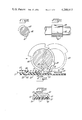
- FIGS. 1 and 2 are top and side elevations, respectively, of a cable-connector assembly embodying the invention
- FIG. 3 is an enlarged end elevation taken approximately along the line 3--3 in FIG. 2;
- FIG. 4 is an enlarged section taken approximately along the line 4--4 in FIG. 1;
- FIG. 5 is a side elevation of a cable end and a stripping tool used in the practice of the invention.
- FIG. 6 is an enlarged elevation similar to FIG. 1 with portions of the connector casing broken open;
- FIGS. 7 and 8 are sections taken approximately along the lines 7--7 and 8--8 in FIG. 6;
- FIG. 9 is a fragmentary section taken approximately along the line 9--9 in FIG. 6;
- FIGS. 10 and 11 are fragmentary side and front elevations of tooling used in the practice of the invention.
- FIG. 12 is an enlarged somewhat diagrammatic section showing the use of the tooling of FIGS. 10, 11;
- FIG. 13 is a fragmentary section taken approximately along the line 13--13 in FIG. 12;
- FIG. 14 is an enlarged fragmentary plan of a terminal strip embodied in the connector of FIG. 6;
- FIG. 15 is similar to FIG. 14 but shows the effect of a further forming step.
- FIG. 16 is a perspective view of a crimped termination following the crimping step.
- an assembly 10 embodying the invention that includes a cable 11 and a connector 12 that, in the illustrated form, couple twenty-four wires 13 and 14 in the cable 10 to ten pin sockets 15 in the end of the connector 12.
- the illustrated cable 11 is a multiple triplex type in which there are eight signal wires 13 each flanked by two ground wires 14.
- the sixteen ground wires 14 are terminated to a common bus plate member 20 that is electrically coupled to the two opposite end sockets 15 of the ten socket array.
- the eight signal wires 13 are electrically coupled respectively to the eight intermediate sockets 15 in the array.
- the illustrated connector 12 includes a base plate 21 having a locking groove 22, a wire guide 23, a series of grooves 24 in one plane for the signal wires 13, and a second planar support for the ground bus plate member 20.
- a plurality of individual plate members 25 are fitted in the grooves 24, one for each signal wire 13.
- the sockets 15 are of the conventional spring type and are nested in the outer end of the connector base plate 21 on the desired centers, typically 1/8 inch apart, so as to plug into a circuit board pin array.
- Thin metal transition strips 26 electrically connect the end sockets 15 to the plate member 20 and the middle sockets 15 to respective ones of the signal wire plate members 25.
- the connector 12 also includes a lock plate 27 having a rib 28 fitting into the groove 22, and a cover plate 29 fitting over and complementing the remaining portions of the base plate 21.
- the signal plate members 25 and the ground bus plate 20 are in spaced but parallel planes, and are relatively spaced longitudinally of the wires 13, 14. This allows sufficient room for the members 25 to be formed for adequate strength, and also allows the termination regions of both the signal and ground wires to be worked from the "top" of the connector base plate 21.
- Each of the wire termination regions involves essentially the same structure which will be explained in terms of a portion of the ground bus plate member 20.
- the member 20 In the case of the member 20, it is slotted to widths somewhat narrower than the wire to be received, with each of the slots 31 being opened in an outwardly tapering throat 32 to one edge of the member 20.
- the member 20 is slotted so that the slot walls longitudinally of the slot are parallel or even somewhat outwardly tapered so as to facilitate the cutting operation.
- large notches 33 are also formed between pairs of the open throated slots 31 and, using the notches 33 to get gripping access, the sides of the slots 31 are slightly pressed together (see FIG. 15) so that the slots 31 become somewhat necked down before opening into the throats 32.
- the plate members 25 are similarly formed and slotted, although single rather than double slots are involved.
- the terminating wire such as one of the wires 14 is laid into the throat 32 and forced down into the slot 31 so as to provide intimate contact between the materials of the wire and the plate member 20 along a short longitudinal length of the wire.
- the wire end portion the material typically being copper, has its sides sheared and coined or mashed into the slot 31. Because the slot is necked down before widening at the throat 32, and the wire is mashed into the slot behind the necked down area, the wire becomes wedged against the linear pull-out.
- all of the plate members 20, 25 have their slots and throats facing the same direction so that all of the wires 13, 14 of the cable 11 can be laid into the throats simultaneously, and then gang terminated by applying force to the wires progressively from the open throats 32 toward the slots 31 so as to first wedge guide the wire end portions over the slots 31 and then force the wire material into the slots by cutting and deforming the wire ends.
- One form of tooling for this purpose is a roller 40 having feet 41 adapted to roll the signal wires 13 into the plate members 25, and a bar type of continuous foot 42 adapted to roll all of the ground wires 14 into the slots 31 in the bus plate member 20.
- the plate members 20, 25 are plated for corrosion resistance using, typically, an indium alloy. As a result, portions of the plating are wiped down into the interfaces between the metal of the wires and that of the plate members.
- a quick heating step using, for example, a quartz infra red lamp to impulse the parts to approximately 400° F. causes intermetallic fusion or melting of the plating and the wire and plate member metals, thus creating a gas tight joint as fused as a brazed or soldered connection.
- the cable-connector assembly 10 is made using additional simple tooling and easily visualized steps starting with a forming and stripping tool having dies 51 (see FIG. 5) for clamping the cable 11 and bending a sharply angled rib 52 in the cable. With the cable so gripped, stripping knives 53 cut into the cable insulation and pull the cut insulation toward but not completely free of the ends of the wires. The cut insulation thus serves to prevent the fine wires of the cable from becoming tangled or dislocated during subsequent handling.
- the stripped cable end is placed in a simple forming and cutting tool (not shown), the cable rib 52 serving as a positive indexing member, for cutting the signal and ground wires 13, 14 to their proper respective lengths and jog bending the signal wires 13 to the shape shown in FIG. 7.
- the so prepared cable end is then placed in the connector base plate 21, the rib 52 fitting in the slot 22 for proper indexing of the parts, and the wires are terminated as described above.
- a quick heating step achieves fusion, and the remaining parts 27 and 29 of the connector 12 are assembled to complete the cable termination.
- the crimping technique there are a number of important advantages of the crimping technique disclosed that may not be immediately apparent.
- One important feature is that it is virtually impossible to overcrimp.
- the crimping force is virtually a pure compression force on the material of the plate member with there being little likelihood of such a force damaging the parts or otherwise jeopardizing the integrity of the termination. It follows from this that no exact gauging or precise tooling is required, so that the terminating technique is well suited for rough and ready, in-the-field use.
- the termination technique disclosed produces a large area, running longitudinally of the wire, gas tight, residual force, connection between the wire and the terminating plate member which, particularly if the plating and heat treating step is utilized, provides a truly diffused electrical connection.
- the large area insures that the joint itself does not constitute an electrical resistance greater than that of the wire itself.
- the gas tight nature keeps out moisture as well as air and other corrosion or oxidation encouraging substances.
Landscapes
- Engineering & Computer Science (AREA)
- Manufacturing & Machinery (AREA)
- Multi-Conductor Connections (AREA)
Abstract
Description
Claims (5)
Priority Applications (1)
| Application Number | Priority Date | Filing Date | Title |
|---|---|---|---|
| US06/017,368 US4288917A (en) | 1978-06-26 | 1979-03-05 | Method of forming connector-cable with crimped electrical terminations |
Applications Claiming Priority (2)
| Application Number | Priority Date | Filing Date | Title |
|---|---|---|---|
| US05/918,813 US4173388A (en) | 1977-02-23 | 1978-06-26 | Connector-cable with crimped electrical terminations |
| US06/017,368 US4288917A (en) | 1978-06-26 | 1979-03-05 | Method of forming connector-cable with crimped electrical terminations |
Related Parent Applications (1)
| Application Number | Title | Priority Date | Filing Date |
|---|---|---|---|
| US05/918,813 Division US4173388A (en) | 1977-02-23 | 1978-06-26 | Connector-cable with crimped electrical terminations |
Publications (1)
| Publication Number | Publication Date |
|---|---|
| US4288917A true US4288917A (en) | 1981-09-15 |
Family
ID=26689780
Family Applications (1)
| Application Number | Title | Priority Date | Filing Date |
|---|---|---|---|
| US06/017,368 Expired - Lifetime US4288917A (en) | 1978-06-26 | 1979-03-05 | Method of forming connector-cable with crimped electrical terminations |
Country Status (1)
| Country | Link |
|---|---|
| US (1) | US4288917A (en) |
Cited By (7)
| Publication number | Priority date | Publication date | Assignee | Title |
|---|---|---|---|---|
| US4382302A (en) * | 1981-03-30 | 1983-05-10 | Watson Douglas E | Weighted training vest having constant weight distribution |
| US4750266A (en) * | 1984-07-24 | 1988-06-14 | Brandeau Edward P | Flat cable connector assembly |
| US4829668A (en) * | 1984-07-24 | 1989-05-16 | Electronic Interconnections Corp. | Flat cable connector having improved contact system |
| US5044999A (en) * | 1984-07-24 | 1991-09-03 | Edward P. Brandeau | Flat cable-connector having improved contact system |
| EP0468512A3 (en) * | 1990-07-26 | 1992-04-22 | Amp Incorporated | Method and apparatus for coupling a connector to a cable |
| EP0485963A1 (en) * | 1990-11-13 | 1992-05-20 | Sumitomo Wiring Systems, Ltd. | Cable wire bending method and cable wire bending device |
| WO2011134873A1 (en) * | 2010-04-27 | 2011-11-03 | Continental Automotive Gmbh | Method for connecting a solid metal piece to a flexible metal strip |
Citations (5)
| Publication number | Priority date | Publication date | Assignee | Title |
|---|---|---|---|---|
| US3573719A (en) * | 1968-09-19 | 1971-04-06 | Amp Inc | Connector for multiple-conductor cable |
| US3864011A (en) * | 1973-08-27 | 1975-02-04 | Amp Inc | Coaxial ribbon cable connector |
| US3909935A (en) * | 1973-01-08 | 1975-10-07 | Amp Inc | Pre-loaded electrical connectors, assembly apparatus and method |
| US3920301A (en) * | 1972-11-28 | 1975-11-18 | Amp Inc | Electrical connectors for flat cable and methods of making same |
| US4086697A (en) * | 1977-06-20 | 1978-05-02 | Akzona Incorporated | Apparatus for making wire termination assemblies |
-
1979
- 1979-03-05 US US06/017,368 patent/US4288917A/en not_active Expired - Lifetime
Patent Citations (5)
| Publication number | Priority date | Publication date | Assignee | Title |
|---|---|---|---|---|
| US3573719A (en) * | 1968-09-19 | 1971-04-06 | Amp Inc | Connector for multiple-conductor cable |
| US3920301A (en) * | 1972-11-28 | 1975-11-18 | Amp Inc | Electrical connectors for flat cable and methods of making same |
| US3909935A (en) * | 1973-01-08 | 1975-10-07 | Amp Inc | Pre-loaded electrical connectors, assembly apparatus and method |
| US3864011A (en) * | 1973-08-27 | 1975-02-04 | Amp Inc | Coaxial ribbon cable connector |
| US4086697A (en) * | 1977-06-20 | 1978-05-02 | Akzona Incorporated | Apparatus for making wire termination assemblies |
Cited By (8)
| Publication number | Priority date | Publication date | Assignee | Title |
|---|---|---|---|---|
| US4382302A (en) * | 1981-03-30 | 1983-05-10 | Watson Douglas E | Weighted training vest having constant weight distribution |
| US4750266A (en) * | 1984-07-24 | 1988-06-14 | Brandeau Edward P | Flat cable connector assembly |
| US4829668A (en) * | 1984-07-24 | 1989-05-16 | Electronic Interconnections Corp. | Flat cable connector having improved contact system |
| WO1989007841A1 (en) * | 1984-07-24 | 1989-08-24 | Brandeau Edward P | Flat cable-connector having improved contact system |
| US5044999A (en) * | 1984-07-24 | 1991-09-03 | Edward P. Brandeau | Flat cable-connector having improved contact system |
| EP0468512A3 (en) * | 1990-07-26 | 1992-04-22 | Amp Incorporated | Method and apparatus for coupling a connector to a cable |
| EP0485963A1 (en) * | 1990-11-13 | 1992-05-20 | Sumitomo Wiring Systems, Ltd. | Cable wire bending method and cable wire bending device |
| WO2011134873A1 (en) * | 2010-04-27 | 2011-11-03 | Continental Automotive Gmbh | Method for connecting a solid metal piece to a flexible metal strip |
Similar Documents
| Publication | Publication Date | Title |
|---|---|---|
| US4173388A (en) | Connector-cable with crimped electrical terminations | |
| US3395381A (en) | Crimpable connecting device for flat conductor cable | |
| US4261632A (en) | Coaxial cable connector | |
| US3521221A (en) | Insulation slicing connector | |
| US3953103A (en) | Plug-in terminal | |
| US3688247A (en) | Cable connectors | |
| US4066319A (en) | Method and apparatus for flat conductor cable termination | |
| US4046446A (en) | Electrical terminal for joining two wires | |
| EP0239422A1 (en) | Electrical connector for flexible flat cable | |
| JP2004528692A (en) | Method and apparatus for using flat flexible cable connector | |
| EP0312550B1 (en) | Insulation displacement terminal | |
| US3920301A (en) | Electrical connectors for flat cable and methods of making same | |
| US5078617A (en) | Piercing insulation displacement board terminal | |
| US4050760A (en) | Solderless electrical contact | |
| US4133596A (en) | Electrical connector | |
| JPH05275129A (en) | Cable clamp device | |
| JPH07122306A (en) | Pressure contact joint connector | |
| US3243757A (en) | Electrical connections | |
| EP0718913B1 (en) | Electric cable for use with a cramping terminal and electric connection means | |
| US4312556A (en) | Electrical connector | |
| DE10140752B4 (en) | Connecting arrangement for holding electrical lines in a junction box | |
| US4288917A (en) | Method of forming connector-cable with crimped electrical terminations | |
| US4650269A (en) | Modular plug connector | |
| US4441779A (en) | Contact device for a multiconductor cable | |
| US5520549A (en) | Connector apparatus, housing, and connecting element |
Legal Events
| Date | Code | Title | Description |
|---|---|---|---|
| STCF | Information on status: patent grant |
Free format text: PATENTED CASE |
|
| AS | Assignment |
Owner name: BRAND-REX WILLIMATIC CT. A CORP OF DE Free format text: ASSIGNMENT OF ASSIGNORS INTEREST.;ASSIGNOR:AKZONA INCORPORATED;REEL/FRAME:004283/0913 Effective date: 19831130 |
|
| AS | Assignment |
Owner name: MANUFACTURERS HANOVER COMMERIAL CORPORATION, A NY Free format text: SECURITY INTEREST;ASSIGNOR:BRAND-REX COMPANY;REEL/FRAME:004289/0418 Effective date: 19831121 Owner name: MANUFACTURERS HANOVER COMMERIAL CORPORATION Free format text: SECURITY INTEREST;ASSIGNOR:BRAND-REX COMPANY;REEL/FRAME:004289/0418 Effective date: 19831121 |
|
| AS | Assignment |
Owner name: BRINTEC SYSTEMS CORPORATION, A CORP OF DE. Free format text: RELEASE BY SECURED PARTY;ASSIGNOR:MANUFACTURER HANOVER COMMERCIAL CORPORATION;REEL/FRAME:004689/0462 Effective date: 19860411 |
|
| AS | Assignment |
Owner name: HUBBELL PREMISE PRODUCTS, INC., A CORP. OF DE, CO Free format text: ASSIGNMENT OF ASSIGNORS INTEREST.;ASSIGNOR:BEINTEC SYSTEMS CORPORATION, A CORP. OF DE;REEL/FRAME:005600/0744 Effective date: 19900712 |
|
| AS | Assignment |
Owner name: HUBBELL INCORPORATED, 584 DERBY MILFORD ROAD, ORAN Free format text: ASSIGNMENT OF ASSIGNORS INTEREST.;ASSIGNOR:HUBBELL PREMISE PRODUCTS, INC., A CORP. OF DE;REEL/FRAME:005673/0169 Effective date: 19900405 |