US4280340A - Universal joint, notably for automobile vehicle transmissions - Google Patents
Universal joint, notably for automobile vehicle transmissions Download PDFInfo
- Publication number
- US4280340A US4280340A US06/076,219 US7621979A US4280340A US 4280340 A US4280340 A US 4280340A US 7621979 A US7621979 A US 7621979A US 4280340 A US4280340 A US 4280340A
- Authority
- US
- United States
- Prior art keywords
- drive element
- insert
- universal joint
- open end
- joint according
- Prior art date
- Legal status (The legal status is an assumption and is not a legal conclusion. Google has not performed a legal analysis and makes no representation as to the accuracy of the status listed.)
- Expired - Lifetime
Links
Images
Classifications
-
- F—MECHANICAL ENGINEERING; LIGHTING; HEATING; WEAPONS; BLASTING
- F16—ENGINEERING ELEMENTS AND UNITS; GENERAL MEASURES FOR PRODUCING AND MAINTAINING EFFECTIVE FUNCTIONING OF MACHINES OR INSTALLATIONS; THERMAL INSULATION IN GENERAL
- F16D—COUPLINGS FOR TRANSMITTING ROTATION; CLUTCHES; BRAKES
- F16D3/00—Yielding couplings, i.e. with means permitting movement between the connected parts during the drive
- F16D3/16—Universal joints in which flexibility is produced by means of pivots or sliding or rolling connecting parts
- F16D3/20—Universal joints in which flexibility is produced by means of pivots or sliding or rolling connecting parts one coupling part entering a sleeve of the other coupling part and connected thereto by sliding or rolling members
- F16D3/22—Universal joints in which flexibility is produced by means of pivots or sliding or rolling connecting parts one coupling part entering a sleeve of the other coupling part and connected thereto by sliding or rolling members the rolling members being balls, rollers, or the like, guided in grooves or sockets in both coupling parts
-
- F—MECHANICAL ENGINEERING; LIGHTING; HEATING; WEAPONS; BLASTING
- F16—ENGINEERING ELEMENTS AND UNITS; GENERAL MEASURES FOR PRODUCING AND MAINTAINING EFFECTIVE FUNCTIONING OF MACHINES OR INSTALLATIONS; THERMAL INSULATION IN GENERAL
- F16D—COUPLINGS FOR TRANSMITTING ROTATION; CLUTCHES; BRAKES
- F16D3/00—Yielding couplings, i.e. with means permitting movement between the connected parts during the drive
- F16D3/16—Universal joints in which flexibility is produced by means of pivots or sliding or rolling connecting parts
- F16D3/20—Universal joints in which flexibility is produced by means of pivots or sliding or rolling connecting parts one coupling part entering a sleeve of the other coupling part and connected thereto by sliding or rolling members
- F16D3/202—Universal joints in which flexibility is produced by means of pivots or sliding or rolling connecting parts one coupling part entering a sleeve of the other coupling part and connected thereto by sliding or rolling members one coupling part having radially projecting pins, e.g. tripod joints
- F16D3/205—Universal joints in which flexibility is produced by means of pivots or sliding or rolling connecting parts one coupling part entering a sleeve of the other coupling part and connected thereto by sliding or rolling members one coupling part having radially projecting pins, e.g. tripod joints the pins extending radially outwardly from the coupling part
- F16D3/2055—Universal joints in which flexibility is produced by means of pivots or sliding or rolling connecting parts one coupling part entering a sleeve of the other coupling part and connected thereto by sliding or rolling members one coupling part having radially projecting pins, e.g. tripod joints the pins extending radially outwardly from the coupling part having three pins, i.e. true tripod joints
-
- F—MECHANICAL ENGINEERING; LIGHTING; HEATING; WEAPONS; BLASTING
- F16—ENGINEERING ELEMENTS AND UNITS; GENERAL MEASURES FOR PRODUCING AND MAINTAINING EFFECTIVE FUNCTIONING OF MACHINES OR INSTALLATIONS; THERMAL INSULATION IN GENERAL
- F16D—COUPLINGS FOR TRANSMITTING ROTATION; CLUTCHES; BRAKES
- F16D3/00—Yielding couplings, i.e. with means permitting movement between the connected parts during the drive
- F16D3/84—Shrouds, e.g. casings, covers; Sealing means specially adapted therefor
- F16D3/843—Shrouds, e.g. casings, covers; Sealing means specially adapted therefor enclosed covers
- F16D3/845—Shrouds, e.g. casings, covers; Sealing means specially adapted therefor enclosed covers allowing relative movement of joint parts due to the flexing of the cover
-
- Y—GENERAL TAGGING OF NEW TECHNOLOGICAL DEVELOPMENTS; GENERAL TAGGING OF CROSS-SECTIONAL TECHNOLOGIES SPANNING OVER SEVERAL SECTIONS OF THE IPC; TECHNICAL SUBJECTS COVERED BY FORMER USPC CROSS-REFERENCE ART COLLECTIONS [XRACs] AND DIGESTS
- Y10—TECHNICAL SUBJECTS COVERED BY FORMER USPC
- Y10S—TECHNICAL SUBJECTS COVERED BY FORMER USPC CROSS-REFERENCE ART COLLECTIONS [XRACs] AND DIGESTS
- Y10S464/00—Rotary shafts, gudgeons, housings, and flexible couplings for rotary shafts
- Y10S464/904—Homokinetic coupling
- Y10S464/905—Torque transmitted via radially extending pin
Definitions
- the present invention relates to universal joints, notably for automobile vehicle transmissions. It relates particularly to the type of universal joint which comprises a drive element, coupled to a drive shaft, substantially bowl-shaped, and provided with at least two ball-races cooperating with rollers borne by a hub fast to a driven shaft, the outer surface of the drive element being substantially parallel with the inner surface of this element so that its outer surface includes concave areas situated, angularly, between the ball-races, a sealing sheath being arranged around the bowl and the driven shaft.
- a universal joint of the previously defined type, is characterized by the fact that it comprises an insert around the open end of the drive element, this insert having an inner surface which mates the outer surface of said element, whilst the outer surface of this insert has a cross-section whose contour is entirely convex, this outer surface being notably a surface of revolution and more particularly cylindrical, so as to serve as a support for the sealing sheath held by clamping on said insert, which ensures filling of the above-said concave areas of the outer surface of the drive element.
- this insert is of plastics material, and is over-molded on to said drive element.
- the outer surface of the insert has, at its end situated at the edge of the drive element, a peripheral bead, notably of semi-circular cross-section, adapted to cooperate with the sealing sheath.
- the parts of the insert ensuring the filling of the concave areas of the outer surface of the drive element comprise, preferably, alveoles or cavities.
- the invention relates also to a part designed to be inserted on a drive element of a universal joint of the previously defined type, which insert has an inner surface adapted to mate the outer surface of the drive element whilst the outer surface of this insert has a cross-section whose contour is entirely convex, this outer surface being notably a surface of revolution and more particularly cylindrical, so as to serve as a support for the sealing sheath, this part ensuring filling of the concave areas of the outer surface of the drive element.
- FIG. 1, of these drawings is an axial section of the drive element and of the insert of a universal joint according to the invention, one of the rollers and the hub fast to the driven shaft being shown diagrammatically.
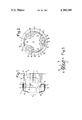
- FIG. 2 is a view from the left, with respect to FIG. 1, of the drive element.
- FIG. 3 lastly, is a detail of the embodiment of FIG. 1 shown on a larger scale.
- a universal joint 1 of the tripod type for an automobile vehicle transmission comprises a drive element 2, coupled to a driving shaft (not shown).
- This element 2 is substantially bowl-shaped and is provided, in the case of a tripod joint, with three rectilinear ball-races 3, parallel to the axis of the bowl 2 and spaced regularly by 120°, as can be clearly seen in FIG. 2.
- rollers g of which one is shown diagrammatically in FIG. 1, borne by a hub m fast to a driven shaft.
- the outer surface 4 (FIG. 2) of the drive element 2 is substantially parallel with the inner surface 5 of the element.
- This outer surface 4 includes, through this fact, concave areas 6 situated, angularly, between the ball-races 3.
- the areas 7 of the outer surface having the same angular position as the ball-races 3 are convex and form protuberances or projections with respect to the concave areas 6.
- the drive element is thus formed with a minimum of relatively expensive material.
- a part 8 is inserted around the open end 2a of the drive element 2.
- This part 8 has an inner surface 9 which mates the outer surface 4 of the element 2; the outer surface 10 of the insert 8 is a cylindrical surface of revolution and coaxial with the element 2, with axis A.
- This cylindrical outer surface 10 serves as a support for sealing sheath 11 which surrounds the open end of the element 2; the other end (not shown) of the sealing sheath 11 is clamped around the driven shaft.
- the insert 8 ensures filling of the concave area 6 by parts such as 12, of the insert 8, having greater thickness.
- the insert 8 is advantageously formed of plastics material; it only extends, axially, from the open end of the element 2, over a reduced length l with respect to the total length L of the element 2.
- the ratio L/l is greater than three.
- the insert 8 is advantageously over-molded on to the end of the element 2.
- the outer surface 10 of the part 8 is provided, at its end situated at the level of the open end of the element 2, with a peripheral bead 13 of semi-circular cross-section which cooperates with the sheath 11.
- the latter extends around the surface 10, beyond the beading 13.
- the sheath 11 can be clamped against the surface 10 by any suitable means, such as a collar or clamp.
- Blind alveoles or cavities 14, opening on the side of the sealing sheath 11, can be provided in the thicker parts 12 of the insert 8 to economize in the plastics material and facilitate molding.
- the blocking, axially, of the insert 8 relative to the element 2 can be ensured by cooperation of notches 15 (FIG. 3), parallel with one another and oriented circumferentially, provided in the convex area 7 of the element 2, with ribs 16 of the insert 8 formed during over-molding.
- This system of notches and ribs could be replaced by ribs provided on the convex area 7 and notches formed by over-molding in the insert 8.
- the insert 8 may be made from polyacetal.
- the solution of the invention enables the economic production of the drive element 2 of a universal joint, with a minimum of material whilst ensuring a "rounding out", that is to say a support surface with a convex contour, at the open end of this element to cooperate with the sealing sheath. In this way good fluid-tightness is produced at the level of the end of the sheath clamped on the element 2.
- this outer surface 10 it suffices however for this outer surface 10 to have a cross-section (in a plane perpendicular to the axis A) whose contour is entirely convex. A slightly elliptical contour could if necessary be suitable. In the case where the outer surface 10 is a surface of revolution, it is not indispensable for it to be cylindrical; it could, for example, be slightly frustoconic.
- roller used in the description and in the claims must be understood in a general sense as denoting any bearing member.
Abstract
The universal joint according to the invention comprises a drive element provided with at least two ball-races cooperating with rollers borne by a hub fast to a driven shaft, the outer surface of the drive element being substantially parallel with the inner surface of this element and including concave areas. It includes an insert having an inner surface which mates the outer surface of the drive element, while the outer surface of this insert has a convex contour to serve as a support for a sealing sheath, the insert ensuring filling of the concave areas. This insert is notably of plastics material over-molded on the drive element.
Description
1. Field of the Invention
The present invention relates to universal joints, notably for automobile vehicle transmissions. It relates particularly to the type of universal joint which comprises a drive element, coupled to a drive shaft, substantially bowl-shaped, and provided with at least two ball-races cooperating with rollers borne by a hub fast to a driven shaft, the outer surface of the drive element being substantially parallel with the inner surface of this element so that its outer surface includes concave areas situated, angularly, between the ball-races, a sealing sheath being arranged around the bowl and the driven shaft.
2. Description of the Prior Art
In such universal joints, the fixing of the sealing sheath on the end of the drive element poses problems. In fact, this sealing sheath covers the outer surface of the end of the drive element. Now, the presence of concave areas in this outer surface constitutes an impediment to the realization of the good fluid-tightness by the clamping of the sealing sheath around the drive element.
Various solutions to this problem have already been proposed. These solutions require, however, improvement, notably from the point of view of simplicity of construction and reduction of cost price, as well as from the point of view of fluid-tightness achieved between the drive element and the sheath.
It is a particular object of the invention to render universal joints of the type concerned such that they respond to the various requirements of practice better than hitherto and notably such that the above-mentioned drawbacks are eliminated or at least reduced.
According to the invention, a universal joint, of the previously defined type, is characterized by the fact that it comprises an insert around the open end of the drive element, this insert having an inner surface which mates the outer surface of said element, whilst the outer surface of this insert has a cross-section whose contour is entirely convex, this outer surface being notably a surface of revolution and more particularly cylindrical, so as to serve as a support for the sealing sheath held by clamping on said insert, which ensures filling of the above-said concave areas of the outer surface of the drive element.
Preferably, this insert is of plastics material, and is over-molded on to said drive element.
The axial arrest of this insert, with respect to the drive element, is advantageously ensured by notches extending circumferentially, in the convex parts of the drive element, situated angularly between the concave areas, these notches cooperating with ribs of the insert.
The outer surface of the insert has, at its end situated at the edge of the drive element, a peripheral bead, notably of semi-circular cross-section, adapted to cooperate with the sealing sheath.
The parts of the insert ensuring the filling of the concave areas of the outer surface of the drive element comprise, preferably, alveoles or cavities.
The invention relates also to a part designed to be inserted on a drive element of a universal joint of the previously defined type, which insert has an inner surface adapted to mate the outer surface of the drive element whilst the outer surface of this insert has a cross-section whose contour is entirely convex, this outer surface being notably a surface of revolution and more particularly cylindrical, so as to serve as a support for the sealing sheath, this part ensuring filling of the concave areas of the outer surface of the drive element.
The invention consists, apart from the above explained features, certain other features which will be more explicitly considered below with regard to a particular embodiment described with reference to the accompanying drawings, but which is in no way limiting.
FIG. 1, of these drawings, is an axial section of the drive element and of the insert of a universal joint according to the invention, one of the rollers and the hub fast to the driven shaft being shown diagrammatically.
FIG. 2 is a view from the left, with respect to FIG. 1, of the drive element.
FIG. 3, lastly, is a detail of the embodiment of FIG. 1 shown on a larger scale.
Referring to the drawings, and more particularly to FIG. 1, there can be seen a universal joint 1 of the tripod type for an automobile vehicle transmission. This joint comprises a drive element 2, coupled to a driving shaft (not shown). This element 2 is substantially bowl-shaped and is provided, in the case of a tripod joint, with three rectilinear ball-races 3, parallel to the axis of the bowl 2 and spaced regularly by 120°, as can be clearly seen in FIG. 2.
These ball-races 3 are adapted to cooperate with rollers g, of which one is shown diagrammatically in FIG. 1, borne by a hub m fast to a driven shaft.
The outer surface 4 (FIG. 2) of the drive element 2 is substantially parallel with the inner surface 5 of the element. This outer surface 4 includes, through this fact, concave areas 6 situated, angularly, between the ball-races 3. The areas 7 of the outer surface having the same angular position as the ball-races 3 are convex and form protuberances or projections with respect to the concave areas 6. The drive element is thus formed with a minimum of relatively expensive material.
It is seen, in FIG. 2, that the outer contour C of the drive element 2 has a shape suggesting that of a star with three arms whose tops have been flattened.
A part 8 is inserted around the open end 2a of the drive element 2. This part 8 has an inner surface 9 which mates the outer surface 4 of the element 2; the outer surface 10 of the insert 8 is a cylindrical surface of revolution and coaxial with the element 2, with axis A.
This cylindrical outer surface 10 serves as a support for sealing sheath 11 which surrounds the open end of the element 2; the other end (not shown) of the sealing sheath 11 is clamped around the driven shaft.
As is clearly seen in FIG. 2, the insert 8 ensures filling of the concave area 6 by parts such as 12, of the insert 8, having greater thickness.
The insert 8 is advantageously formed of plastics material; it only extends, axially, from the open end of the element 2, over a reduced length l with respect to the total length L of the element 2. For example, the ratio L/l is greater than three.
The insert 8 is advantageously over-molded on to the end of the element 2.
As seen in FIGS. 1 and 3, the outer surface 10 of the part 8 is provided, at its end situated at the level of the open end of the element 2, with a peripheral bead 13 of semi-circular cross-section which cooperates with the sheath 11. The latter extends around the surface 10, beyond the beading 13. The sheath 11 can be clamped against the surface 10 by any suitable means, such as a collar or clamp.
Blind alveoles or cavities 14, opening on the side of the sealing sheath 11, can be provided in the thicker parts 12 of the insert 8 to economize in the plastics material and facilitate molding.
The blocking, axially, of the insert 8 relative to the element 2 can be ensured by cooperation of notches 15 (FIG. 3), parallel with one another and oriented circumferentially, provided in the convex area 7 of the element 2, with ribs 16 of the insert 8 formed during over-molding. This system of notches and ribs could be replaced by ribs provided on the convex area 7 and notches formed by over-molding in the insert 8.
By way of example, the insert 8 may be made from polyacetal.
The solution of the invention enables the economic production of the drive element 2 of a universal joint, with a minimum of material whilst ensuring a "rounding out", that is to say a support surface with a convex contour, at the open end of this element to cooperate with the sealing sheath. In this way good fluid-tightness is produced at the level of the end of the sheath clamped on the element 2.
It is clear that the simplest solution consists of providing an outer, and cylindrical, surface of revolution 10, as shown in the drawings.
It suffices however for this outer surface 10 to have a cross-section (in a plane perpendicular to the axis A) whose contour is entirely convex. A slightly elliptical contour could if necessary be suitable. In the case where the outer surface 10 is a surface of revolution, it is not indispensable for it to be cylindrical; it could, for example, be slightly frustoconic.
It should be noted that the term "roller" used in the description and in the claims must be understood in a general sense as denoting any bearing member.
Claims (10)
1. A universal joint for a transmission, comprising:
(a) a substantially bowl-shaped drive element coupled to a drive shaft for transferring torque to a driven shaft, said element having an open end, a length L with respect to its axis of rotation, and at least two ball races for receiving rollers borne by a hub connected fast to said driven shaft, said drive element further having an outer surface substantially parallel with its inner surface so that the outer surface of the drive element includes concave areas angularly situated between the ball-races;
(b) a sealing sheath having an open end circumferentially mounted around the open end of the bowl of said drive element, and
(c) an insert circumferentially mounted around the open end of the bowl of the drive element for mounting said open end of said sealing sheath around said drive element, said insert having a length of less than L along its axis of rotation, and an inner surface which is complementary to the outer surface of said drive element for filling said concave areas of said outer surface of said drive element, and an outer surface which is entirely convex for sealingly engaging said open end of said sealing sheath.
2. The universal joint of claim 1, wherein the length L of said drive element is three or more times greater than the length of said insert.
3. The universal joint of claim 1 wherein said bowl-shaped drive element further includes a coupling located opposite its open end for transferring substantially all the torque transferred between said drive shaft and said drive element.
4. The universal joint according to claim 1, wherein said outer surface of said insert is a surface of revolution.
5. The universal joint according to claim 1, wherein said outer surface of said insert is cylindrical.
6. The universal joint according to claim 1, wherein said insert is made from plastics material.
7. The universal joint according to claim 1, wherein said insert in over-molded on the drive element.
8. The universal joint according to claim 1 wherein movement of said insert relative to said drive element is arrested by a plurality of complementary notches and ribs extending circumferentially around the inner surface of said insert and said outer surface of the drive element.
9. The universal joint according to claim 8, wherein the outer surface of said insert has, at its end situated around the open end of said drive element, a peripheral bead of semi-circular cross-section which is complementary to an annular groove situated around the interior of the edge of the open end of said sealing sheath.
10. The universal joint according to claim 1, wherein the parts of the insert filling said concave areas of the outer surface of the drive element include cavities.
Applications Claiming Priority (2)
| Application Number | Priority Date | Filing Date | Title |
|---|---|---|---|
| FR7830553 | 1978-10-27 | ||
| FR7830553A FR2439905A1 (en) | 1978-10-27 | 1978-10-27 | IMPROVEMENTS ON UNIVERSAL JOINTS, ESPECIALLY FOR TRANSMISSIONS OF MOTOR VEHICLES |
Publications (1)
| Publication Number | Publication Date |
|---|---|
| US4280340A true US4280340A (en) | 1981-07-28 |
Family
ID=9214212
Family Applications (1)
| Application Number | Title | Priority Date | Filing Date |
|---|---|---|---|
| US06/076,219 Expired - Lifetime US4280340A (en) | 1978-10-27 | 1979-09-17 | Universal joint, notably for automobile vehicle transmissions |
Country Status (5)
| Country | Link |
|---|---|
| US (1) | US4280340A (en) |
| EP (1) | EP0010999A1 (en) |
| JP (1) | JPS5560726A (en) |
| ES (1) | ES483268A1 (en) |
| FR (1) | FR2439905A1 (en) |
Cited By (19)
| Publication number | Priority date | Publication date | Assignee | Title |
|---|---|---|---|---|
| US4417880A (en) * | 1981-09-17 | 1983-11-29 | Toyota Jidosha Kogyo Kabushiki Kaisha | Joint assembly |
| JPS60188626A (en) * | 1984-03-14 | 1985-09-26 | ジ−ケ−エヌ・オ−トモ−テイブ・コンポ−ネンツ・インコ−ポレ−テツド | Self-aligning tulip type cover |
| DE3726166A1 (en) * | 1986-08-07 | 1988-02-11 | Gkn Automotive Components Inc | TULIP LID ARRANGEMENT FOR A JOINT TRIPODE JOINT |
| US4936811A (en) * | 1989-03-20 | 1990-06-26 | Wynn's-Precision, Inc. | Boot assembly for constant velocity joint |
| US5851151A (en) * | 1995-03-23 | 1998-12-22 | Stanley Mechanics Tools | Pinless impact universal joint |
| EP0915264A2 (en) † | 1997-11-04 | 1999-05-12 | Draftex Industries Limited | Protective bellows |
| US6471595B1 (en) * | 1999-07-19 | 2002-10-29 | Gkn Automotive Ag | Rotary joint |
| FR2833665A1 (en) * | 2001-12-17 | 2003-06-20 | Gkn Glaenzer Spicer | Corrugated boot for transmission joint has heel at each end to ensure sealed contact with shaft or component fixed to shaft |
| US20030134076A1 (en) * | 2001-12-17 | 2003-07-17 | Joachim Wette | Tripod joint assembly |
| US20040056434A1 (en) * | 2002-07-26 | 2004-03-25 | Carl Freudenberg Kg | Axle boot |
| DE10322902A1 (en) * | 2003-05-21 | 2004-12-16 | Gkn Driveline International Gmbh | bellows |
| US20050288106A1 (en) * | 2004-06-23 | 2005-12-29 | Gehrke Glenn F | Universal joint assembly |
| US20060079337A1 (en) * | 2004-03-31 | 2006-04-13 | Toyo Tire & Rubber Co., Ltd. | Joint boot |
| US20060107615A1 (en) * | 2004-10-19 | 2006-05-25 | Toyo Tire & Rubber Co., Ltd. | Joint boot |
| US20070026953A1 (en) * | 2004-11-24 | 2007-02-01 | Takenori Ohshita | Joint boot |
| US20080157484A1 (en) * | 2004-12-15 | 2008-07-03 | Trelleborg Prodyn | Multilobed Socket For Protection of a Vehicle Transmission |
| US20090036223A1 (en) * | 2007-08-02 | 2009-02-05 | American Axle & Manufacturing, Inc. | Universal joint with bearing cup retention mechanism and method |
| US7611415B1 (en) * | 2005-01-19 | 2009-11-03 | Gkn Driveline North America, Inc. | Shaft assembly with integrated constant velocity joint |
| US20220049743A1 (en) * | 2020-08-13 | 2022-02-17 | Steering Solutions Ip Holding Corporation | Tripot joint with assembly and disassembly ring |
Families Citing this family (8)
| Publication number | Priority date | Publication date | Assignee | Title |
|---|---|---|---|---|
| JPS58142455U (en) * | 1982-03-19 | 1983-09-26 | キ−パ−株式会社 | flexible boots |
| US5676599A (en) * | 1993-05-03 | 1997-10-14 | Lohr & Bromkamp Gmbh | Outer joint part for a tripod joint |
| DE4314503C1 (en) * | 1993-05-03 | 1994-12-01 | Loehr & Bromkamp Gmbh | Outer part for a tripot joint |
| US6089574A (en) * | 1998-03-11 | 2000-07-18 | Salflex Polymers Ltd. | Boot with insertable bushing |
| FR2796686B1 (en) * | 1999-07-19 | 2001-12-07 | Gkn Glaenzer Spicer | BELLOWS AND CORRESPONDING TRANSMISSION JOINT |
| JP4520946B2 (en) * | 2003-07-25 | 2010-08-11 | 東洋ゴム工業株式会社 | Joint boots |
| WO2005010388A1 (en) * | 2003-07-25 | 2005-02-03 | Toyo Tire & Rubber Co., Ltd. | Joint boot |
| EP1803955B1 (en) * | 2004-10-19 | 2011-01-12 | Toyo Tire & Rubber Co., Ltd . | Joint boot |
Citations (6)
| Publication number | Priority date | Publication date | Assignee | Title |
|---|---|---|---|---|
| FR1268917A (en) * | 1960-10-03 | 1961-08-04 | Brd Co Ltd | Improvements to ball joints |
| US3318108A (en) * | 1964-07-23 | 1967-05-09 | Citroen Sa Andre | Elastic universal sliding joint for driving half-shafts of motor vehicle driving wheels |
| US3792596A (en) * | 1972-01-25 | 1974-02-19 | Glaenzer Spicer Sa | High-capacity homokinetic coupling |
| US3817057A (en) * | 1972-02-18 | 1974-06-18 | Glaenzer Spicer Sa | Protective arrangement for a rotary power transmission coupling |
| US3906747A (en) * | 1972-06-01 | 1975-09-23 | Glaenzer Spicer Sa | Double tripod homokinetic joint |
| US4175407A (en) * | 1977-03-04 | 1979-11-27 | Glaenzer Spicer | Homokinetic joint allowing a large angular displacement |
Family Cites Families (3)
| Publication number | Priority date | Publication date | Assignee | Title |
|---|---|---|---|---|
| JPS5138136B2 (en) * | 1971-09-17 | 1976-10-20 | ||
| FR2230895A2 (en) * | 1973-05-22 | 1974-12-20 | Glaenzer Spicer Sa | Constant velocity joint with three-arm roller supports - uses flexible bellows seal to achieve compact dimensions |
| JPS54132046A (en) * | 1978-04-05 | 1979-10-13 | Honda Motor Co Ltd | Slide type uniform velocity universal joint |
-
1978
- 1978-10-27 FR FR7830553A patent/FR2439905A1/en active Granted
-
1979
- 1979-08-09 ES ES483268A patent/ES483268A1/en not_active Expired
- 1979-09-17 US US06/076,219 patent/US4280340A/en not_active Expired - Lifetime
- 1979-09-21 EP EP79400675A patent/EP0010999A1/en not_active Withdrawn
- 1979-10-16 JP JP13347879A patent/JPS5560726A/en active Pending
Patent Citations (6)
| Publication number | Priority date | Publication date | Assignee | Title |
|---|---|---|---|---|
| FR1268917A (en) * | 1960-10-03 | 1961-08-04 | Brd Co Ltd | Improvements to ball joints |
| US3318108A (en) * | 1964-07-23 | 1967-05-09 | Citroen Sa Andre | Elastic universal sliding joint for driving half-shafts of motor vehicle driving wheels |
| US3792596A (en) * | 1972-01-25 | 1974-02-19 | Glaenzer Spicer Sa | High-capacity homokinetic coupling |
| US3817057A (en) * | 1972-02-18 | 1974-06-18 | Glaenzer Spicer Sa | Protective arrangement for a rotary power transmission coupling |
| US3906747A (en) * | 1972-06-01 | 1975-09-23 | Glaenzer Spicer Sa | Double tripod homokinetic joint |
| US4175407A (en) * | 1977-03-04 | 1979-11-27 | Glaenzer Spicer | Homokinetic joint allowing a large angular displacement |
Cited By (36)
| Publication number | Priority date | Publication date | Assignee | Title |
|---|---|---|---|---|
| US4417880A (en) * | 1981-09-17 | 1983-11-29 | Toyota Jidosha Kogyo Kabushiki Kaisha | Joint assembly |
| JPS60188626A (en) * | 1984-03-14 | 1985-09-26 | ジ−ケ−エヌ・オ−トモ−テイブ・コンポ−ネンツ・インコ−ポレ−テツド | Self-aligning tulip type cover |
| US4605384A (en) * | 1984-03-14 | 1986-08-12 | Gkn Automotive Components Incorporated | Self-aligning tripod joint tulip cover and constant velocity joint incorporating same |
| US4795404A (en) * | 1984-03-14 | 1989-01-03 | Gkn Automotive Components Inc. | Tripod constant velocity joint and sealing retainer therefor |
| JPH0440567B2 (en) * | 1984-03-14 | 1992-07-03 | Jii Kee Enu Ootomooteibu Konhoonentsu Inc | |
| DE3726166A1 (en) * | 1986-08-07 | 1988-02-11 | Gkn Automotive Components Inc | TULIP LID ARRANGEMENT FOR A JOINT TRIPODE JOINT |
| US4936811A (en) * | 1989-03-20 | 1990-06-26 | Wynn's-Precision, Inc. | Boot assembly for constant velocity joint |
| US5851151A (en) * | 1995-03-23 | 1998-12-22 | Stanley Mechanics Tools | Pinless impact universal joint |
| EP0915264A2 (en) † | 1997-11-04 | 1999-05-12 | Draftex Industries Limited | Protective bellows |
| EP0915264B2 (en) † | 1997-11-04 | 2010-02-10 | Trelleborg Ab | Protective bellows |
| US6471595B1 (en) * | 1999-07-19 | 2002-10-29 | Gkn Automotive Ag | Rotary joint |
| FR2833665A1 (en) * | 2001-12-17 | 2003-06-20 | Gkn Glaenzer Spicer | Corrugated boot for transmission joint has heel at each end to ensure sealed contact with shaft or component fixed to shaft |
| DE10161987A1 (en) * | 2001-12-17 | 2003-07-24 | Gkn Automotive Gmbh | Tripodegelenkanordnung |
| DE10161987C2 (en) * | 2001-12-17 | 2003-11-13 | Gkn Automotive Gmbh | Tripodegelenkanordnung |
| US6902486B2 (en) | 2001-12-17 | 2005-06-07 | Gkn Automotive Gmbh | Tripod joint assembly |
| US20030134076A1 (en) * | 2001-12-17 | 2003-07-17 | Joachim Wette | Tripod joint assembly |
| US20040056434A1 (en) * | 2002-07-26 | 2004-03-25 | Carl Freudenberg Kg | Axle boot |
| US8028999B2 (en) | 2002-07-26 | 2011-10-04 | Carl Freudenberg Kg | Axle boot |
| DE10322902A1 (en) * | 2003-05-21 | 2004-12-16 | Gkn Driveline International Gmbh | bellows |
| DE10322902B4 (en) * | 2003-05-21 | 2010-09-09 | Gkn Driveline International Gmbh | bellows |
| US20070042827A1 (en) * | 2003-05-21 | 2007-02-22 | Markus Deisinger | Convoluted boot assembly |
| US7607986B2 (en) | 2003-05-21 | 2009-10-27 | Gkn Driveline International Gmbh | Convoluted boot assembly |
| US20060079337A1 (en) * | 2004-03-31 | 2006-04-13 | Toyo Tire & Rubber Co., Ltd. | Joint boot |
| US7264549B2 (en) | 2004-03-31 | 2007-09-04 | Toyo Tire & Rubber Co., Ltd. | Joint boot |
| US20050288106A1 (en) * | 2004-06-23 | 2005-12-29 | Gehrke Glenn F | Universal joint assembly |
| US7147564B2 (en) | 2004-06-23 | 2006-12-12 | American Axle & Manufacturing, Inc. | Universal joint assembly |
| US7585227B2 (en) * | 2004-10-19 | 2009-09-08 | Toyo Tire & Rubber Co., Ltd. | Joint boot |
| US20060107615A1 (en) * | 2004-10-19 | 2006-05-25 | Toyo Tire & Rubber Co., Ltd. | Joint boot |
| US7347787B2 (en) | 2004-11-24 | 2008-03-25 | Toyo Tire & Rubber Co., Ltd. | Joint boot |
| US20070026953A1 (en) * | 2004-11-24 | 2007-02-01 | Takenori Ohshita | Joint boot |
| US20080157484A1 (en) * | 2004-12-15 | 2008-07-03 | Trelleborg Prodyn | Multilobed Socket For Protection of a Vehicle Transmission |
| US7611415B1 (en) * | 2005-01-19 | 2009-11-03 | Gkn Driveline North America, Inc. | Shaft assembly with integrated constant velocity joint |
| US20090036223A1 (en) * | 2007-08-02 | 2009-02-05 | American Axle & Manufacturing, Inc. | Universal joint with bearing cup retention mechanism and method |
| US7887422B2 (en) | 2007-08-02 | 2011-02-15 | American Axle & Manufacturing, Inc. | Universal joint with bearing cup retention mechanism |
| US20220049743A1 (en) * | 2020-08-13 | 2022-02-17 | Steering Solutions Ip Holding Corporation | Tripot joint with assembly and disassembly ring |
| US11698108B2 (en) * | 2020-08-13 | 2023-07-11 | Steering Solutions Ip Holding Corporation | Tripot joint with assembly and disassembly ring |
Also Published As
| Publication number | Publication date |
|---|---|
| EP0010999A1 (en) | 1980-05-14 |
| ES483268A1 (en) | 1980-04-16 |
| FR2439905B1 (en) | 1982-03-12 |
| FR2439905A1 (en) | 1980-05-23 |
| JPS5560726A (en) | 1980-05-08 |
Similar Documents
| Publication | Publication Date | Title |
|---|---|---|
| US4280340A (en) | Universal joint, notably for automobile vehicle transmissions | |
| US4320632A (en) | Sliding universal joints notably for automobile vehicle transmissions | |
| CA1062928A (en) | Stroking universal joint housing | |
| US4403781A (en) | Sealing assembly for universal joint | |
| JP5594926B2 (en) | Fitting device | |
| US5591085A (en) | Tripod constant velocity universal joint incorporating a retention system for the roller assemblies | |
| GB2107412A (en) | Sealing boot for a universal joint | |
| US5067198A (en) | Wiper pivot | |
| US6361444B1 (en) | Flexible boot assembly for a constant velocity joint | |
| EP0915264A2 (en) | Protective bellows | |
| JPS6211235B2 (en) | ||
| US6464233B1 (en) | Bellows-type cover member | |
| JPH0562649B2 (en) | ||
| GB2070737A (en) | Drive coupling | |
| US6077166A (en) | Dust guard and cross assembly for a universal joint | |
| JP3559444B2 (en) | Bellows device and power transmission coupling | |
| HU212893B (en) | Drive unit in particular for vehicle windscreen wipers | |
| US5588915A (en) | Seal and seal guard assembly for universal joint | |
| EP0021734A1 (en) | Bearing sealing assembly | |
| JPS6219609B2 (en) | ||
| US4904227A (en) | Stopper apparatus for inner member in sliding universal joints | |
| US6406373B1 (en) | Dust guard and cross assembly for a universal joint | |
| US11261906B2 (en) | Ball joint for a two-point link and two-point-link with such ball joint | |
| CN109153401B (en) | Sealing device | |
| US6095925A (en) | Seal assembly and seal guard for a universal joint |
Legal Events
| Date | Code | Title | Description |
|---|---|---|---|
| STCF | Information on status: patent grant |
Free format text: PATENTED CASE |