US426880A - Steam-separator - Google Patents
Steam-separator Download PDFInfo
- Publication number
- US426880A US426880A US426880DA US426880A US 426880 A US426880 A US 426880A US 426880D A US426880D A US 426880DA US 426880 A US426880 A US 426880A
- Authority
- US
- United States
- Prior art keywords
- steam
- drum
- plates
- chamber
- valve
- Prior art date
- Legal status (The legal status is an assumption and is not a legal conclusion. Google has not performed a legal analysis and makes no representation as to the accuracy of the status listed.)
- Expired - Lifetime
Links
- 238000010276 construction Methods 0.000 description 12
- 239000012530 fluid Substances 0.000 description 6
- XLYOFNOQVPJJNP-UHFFFAOYSA-N water Substances O XLYOFNOQVPJJNP-UHFFFAOYSA-N 0.000 description 6
- NTHWMYGWWRZVTN-UHFFFAOYSA-N Sodium silicate Chemical compound [Na+].[Na+].[O-][Si]([O-])=O NTHWMYGWWRZVTN-UHFFFAOYSA-N 0.000 description 4
- 230000005494 condensation Effects 0.000 description 4
- 239000004519 grease Substances 0.000 description 4
- 239000002245 particle Substances 0.000 description 4
- 238000005192 partition Methods 0.000 description 4
- 235000019353 potassium silicate Nutrition 0.000 description 4
- 230000002459 sustained Effects 0.000 description 4
- 102100017923 ACOT12 Human genes 0.000 description 2
- 101710008266 ACOT12 Proteins 0.000 description 2
- 241000282326 Felis catus Species 0.000 description 2
- 238000009833 condensation Methods 0.000 description 2
- 239000012535 impurity Substances 0.000 description 2
- 239000000203 mixture Substances 0.000 description 2
Images

Classifications
-
- B—PERFORMING OPERATIONS; TRANSPORTING
- B01—PHYSICAL OR CHEMICAL PROCESSES OR APPARATUS IN GENERAL
- B01D—SEPARATION
- B01D46/00—Filters or filtering processes specially modified for separating dispersed particles from gases or vapours
- B01D46/0027—Filters or filtering processes specially modified for separating dispersed particles from gases or vapours with additional separating or treating functions
- B01D46/003—Filters or filtering processes specially modified for separating dispersed particles from gases or vapours with additional separating or treating functions including coalescing means for the separation of liquid
- B01D46/0031—Filters or filtering processes specially modified for separating dispersed particles from gases or vapours with additional separating or treating functions including coalescing means for the separation of liquid with collecting, draining means
-
- Y—GENERAL TAGGING OF NEW TECHNOLOGICAL DEVELOPMENTS; GENERAL TAGGING OF CROSS-SECTIONAL TECHNOLOGIES SPANNING OVER SEVERAL SECTIONS OF THE IPC; TECHNICAL SUBJECTS COVERED BY FORMER USPC CROSS-REFERENCE ART COLLECTIONS [XRACs] AND DIGESTS
- Y10—TECHNICAL SUBJECTS COVERED BY FORMER USPC
- Y10T—TECHNICAL SUBJECTS COVERED BY FORMER US CLASSIFICATION
- Y10T137/00—Fluid handling
- Y10T137/7287—Liquid level responsive or maintaining systems
- Y10T137/7297—With second diverse control
- Y10T137/73—Manual control
Definitions
- the object of my invention is to provide a novel apparatus for separating the water of condensation from live steam and eliminating therefrom the particles of grease, oil, or other impurities taken up by the steam in passing from the boiler to the steam-chests of the cylinders.
- my invention involves the peculiar features of construction and the combination or arrangement of devices hereinafter described,andr
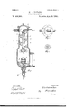
- Figure 1 is a central vertical section of a trap embodying my invention.
- Fig. 2 is a plan view of the same with the cap or cover removed.
- Fig. 3 is a top View of the valvechamber.
- yFig. 4 is a vertical central section showing a modified construction.
- Figo is a plan view of Fig. 4, the cover being removed.
- the reference-numeral 1 denotes a drum or vessel, preferably of cylindrical form, and of small diameter compared with its considerable depth. This drum is closed at its top by a cover 2, bolted to a flange 3, the joint being steam-tight.
- the numeral 3 denotes the steam-pipe, which enters the drum at or near the top.
- baffle-plates 4 having preferably a downward inclination, and projecting from opposite walls of the drum alternately, their edges approaching the wall opposite that on which they are mounted, but not meeting, in order that narrow passages may be left for the steam.
- the pipe 5 leads to the steamchest or other point to which the live steam 1s to be conveyed.
- valve-chamber 10 Tapped into or otherwise attached to the bottom of this chamber is a valve-chamber 10, of any suitable construction, in which is arranged a balanced valve 12, carried by a stem 13, which rises into the chamber 8.
- a float 14 Upon the valve-stem is mounted a float 14, of suitable size and form, by which the balanced valve may be unseated as the iiuid rises in the chamber 8.
- the lower part of the valve-chamber 10 opens into a pipe 15, which may, if desired, be provided with a suitable cock.
- I may substitute the modified construction shown in Fig. 4 in place of that described.
- the interior of the drum is provided with a partition or plate 16,which is arranged a little to one side of the center, as shown inFig. 5, where it forms the vertical conveyer 17 for the steam.
- the battle-plates 4 extend alternately from the plate or partition 16 and the opposite wall of thedrum. It will be seen that this construction is in principle and operation the same as that already described.
- a balanced valve 18 mounted on a pivot 19
- a steam-purifier consisting of a vertically-arranged closed drum having at its uppcr end a steam-inlet and a steam-outlet and at its lower end a valvcd water-discharge, a series of inclined baiiie-platcs alternately projecting past each other from opposite side portions of the drum and forming a zigzag steam-passage, a vertical steamconveyer opening at its bottom beneath the lowermost bafle-plate and at its upper end connected with the steam-outlet, and a float sustained by the water in the base of the drum and connected with the valve in the water-discharge, substantially as described.
- a steam-purifier consisting of a vertically-arranged tight drum having at its upper end a steam-inlet and a stea1n-outlet, a series of inclined baffle-plates alternately projecting past each other from opposite sides of the drum and each having an orifice, and a steamconveyer tube extending vertically through the orifices in the bathe-plates, opening at its lower end beneath the lowermost plate and having its upper end connected with the steam-outlet, substantially as described.
- a steam-purifier consisting of. an. upright drum having at its top a steam-inlet and a steam-outlet and at its bottom a valved water-discharge and blow-off, a series of baffle plates alternately projecting past cach other from opposite sides of the drum and each having an orifice, a vertical steam-conveyor tube extending' through the orifices in the bathe-plates and connected with the steamoutlet, and a float sustained by the water in the base of the drum and connected with the valve, substantially as described.
Description
(No Model.) 2 Sheets-Sheet 1'.
W. A. TAYLOR. STEAM SBPARATOR.
No. 428,880. P8tentedApr.29,189o.
Y (No ModexQ) 2 SheetS-Sheet 2.
W. A. TAYLOR. STEAM SBPARATQR.
No. 428,880. B88811888 Apr. 29, 1890.V
me mams ven-.ns co8. muro-wma., msmnm'nu, n. c.
UNITED STATES PATENT OFFICE.
WALTER ANDERSON TAYLOR, OF NEW ORLEANS, LOUISIANA.
STEAM-SEPARATO R.
SPECIFICATION forming part 0f Letters Patent N0. 426,880, dated. April 29, 1890.
Application filed November 13, 1889. Serial No. 330,148. (No model.)
To all whom it may concern:
Be it known that I, WALTER ANDERSONv TAYLOR@ citizen of the United States, residing at New Orleans', in the parish of Orleans and State of Louisiana, have invented certain new and useful Improvements in Steam-Separators; and l do hereby declare that the following is a full, clear, and exact description of the same, reference being had to the annexed drawings, making a part of this specification, and to the figures of reference marked thereon.
The object of my invention is to provide a novel apparatus for separating the water of condensation from live steam and eliminating therefrom the particles of grease, oil, or other impurities taken up by the steam in passing from the boiler to the steam-chests of the cylinders. To accomplish this object my invention involves the peculiar features of construction and the combination or arrangement of devices hereinafter described,andr
specifically set forth in the claims, reference Abeing made to the accompanying drawings,
in which- Figure 1 is a central vertical section of a trap embodying my invention. Fig. 2 is a plan view of the same with the cap or cover removed. Fig. 3 is a top View of the valvechamber. yFig. 4 is a vertical central section showing a modified construction. Figo is a plan view of Fig. 4, the cover being removed.
In the said drawings the reference-numeral 1 denotes a drum or vessel, preferably of cylindrical form, and of small diameter compared with its considerable depth. This drum is closed at its top by a cover 2, bolted to a flange 3, the joint being steam-tight.
The numeral 3 denotes the steam-pipe, which enters the drum at or near the top. Formed or mounted upon the interior face of the drum are baffle-plates 4, having preferably a downward inclination, and projecting from opposite walls of the drum alternately, their edges approaching the wall opposite that on which they are mounted, but not meeting, in order that narrow passages may be left for the steam. Any required number of cates with a conveyer-tube 6, passing through or by the several plates 4 until its flaring or expanded mouth 7 drops somewhat below the lower plate. The pipe 5 leads to the steamchest or other point to which the live steam 1s to be conveyed.
In the lower portion of the drum 1, which may be slightly expanded for the purpose, 1s the fluid and sediment chamber 8, which is supplied with a water-glass or gage-tube 9. Tapped into or otherwise attached to the bottom of this chamber is a valve-chamber 10, of any suitable construction, in which is arranged a balanced valve 12, carried by a stem 13, which rises into the chamber 8. Upon the valve-stem is mounted a float 14, of suitable size and form, by which the balanced valve may be unseated as the iiuid rises in the chamber 8. The lower part of the valve-chamber 10 opens into a pipe 15, which may, if desired, be provided with a suitable cock. As the live steam enters by way of the pipe 3, it is compelled to iiow downward over the surfaces of the baiile-plates 4, whereby any condensations of vapor or particles of oil or grease carried by it are deposited and caused to adhere to said plates, whence the fluid trickles downward and falls into the chamber 8,While the dry and pure steam enters the mouth of the conveyer 6 and passes to the engine. As the fluid accumulates in the chamber 8, the fioat is raised and a portion is discharged until the float falls sufficiently to seat the valve. It sediment accumulates in the chamber, the steam-pressure will ordinarily blow it out through the discharge-pipe.
I may substitute the modified construction shown in Fig. 4 in place of that described. In this form of trap the interior of the drum is provided with a partition or plate 16,which is arranged a little to one side of the center, as shown inFig. 5, where it forms the vertical conveyer 17 for the steam. The battle-plates 4 extend alternately from the plate or partition 16 and the opposite wall of thedrum. It will be seen that this construction is in principle and operation the same as that already described.
In the bottom of the drum is arranged a balanced valve 18, mounted on a pivot 19,
IOO
and having a stem 13 extending from the outlet 2l, in which the valve is pivoted, into the lower part of the drum. On the stem is mounted the iioat 14. A separate blow-ofi' pipe 23 is arranged in the bottom of the drum and provided with a cock of any suitable form. A water-glass is attached to the drum in the same manner as in the construction described. In this modified form the steam enters, as before, through the inlet-pipe 3 and fiows downward over the baftle-plates until it reaches the mouth of the conveyer or passage 17. Passing up through the latter it enters the pipe 5 and is conveyed to the engme.
That l claim ifsl. A steam-purifier consisting of a vertically-arranged closed drum having at its uppcr end a steam-inlet and a steam-outlet and at its lower end a valvcd water-discharge, a series of inclined baiiie-platcs alternately projecting past each other from opposite side portions of the drum and forming a zigzag steam-passage, a vertical steamconveyer opening at its bottom beneath the lowermost bafle-plate and at its upper end connected with the steam-outlet, and a float sustained by the water in the base of the drum and connected with the valve in the water-discharge, substantially as described.
2. A steam-purifier consisting of a vertically-arranged tight drum having at its upper end a steam-inlet and a stea1n-outlet,a series of inclined baffle-plates alternately projecting past each other from opposite sides of the drum and each having an orifice, and a steamconveyer tube extending vertically through the orifices in the bathe-plates, opening at its lower end beneath the lowermost plate and having its upper end connected with the steam-outlet, substantially as described.
3. A steam-purifier consisting of. an. upright drum having at its top a steam-inlet and a steam-outlet and at its bottom a valved water-discharge and blow-off, a series of baffle plates alternately projecting past cach other from opposite sides of the drum and each having an orifice, a vertical steam-conveyor tube extending' through the orifices in the bathe-plates and connected with the steamoutlet, and a float sustained by the water in the base of the drum and connected with the valve, substantially as described.
In testimony whereof I have hereunto subscribed my name in the presence of two wittnesses.
WALTER ANDERSON TAYLOR.
lVitnesses:
FREDERIC CooK, JAMES DAVIS.
Publications (1)
| Publication Number | Publication Date |
|---|---|
| US426880A true US426880A (en) | 1890-04-29 |
Family
ID=2495790
Family Applications (1)
| Application Number | Title | Priority Date | Filing Date |
|---|---|---|---|
| US426880D Expired - Lifetime US426880A (en) | Steam-separator |
Country Status (1)
| Country | Link |
|---|---|
| US (1) | US426880A (en) |
Cited By (6)
| Publication number | Priority date | Publication date | Assignee | Title |
|---|---|---|---|---|
| US2462220A (en) * | 1946-02-23 | 1949-02-22 | Royce L Parker | Steam treating apparatus |
| US2648347A (en) * | 1953-08-11 | Automatic high-pressure valve | ||
| US4468962A (en) * | 1982-03-05 | 1984-09-04 | Armstrong International, Inc. | Energy loss detection system |
| US4867767A (en) * | 1985-09-17 | 1989-09-19 | Tlv Co., Ltd. | Condensate separating and discharging device with a specially dimensioned trap section |
| US5030262A (en) * | 1987-11-02 | 1991-07-09 | La-Man Corporation | Air vapor trap and drain therefore |
| US5114443A (en) * | 1987-11-02 | 1992-05-19 | La-Man Corporation | Air line vapor trap |
-
0
- US US426880D patent/US426880A/en not_active Expired - Lifetime
Cited By (6)
| Publication number | Priority date | Publication date | Assignee | Title |
|---|---|---|---|---|
| US2648347A (en) * | 1953-08-11 | Automatic high-pressure valve | ||
| US2462220A (en) * | 1946-02-23 | 1949-02-22 | Royce L Parker | Steam treating apparatus |
| US4468962A (en) * | 1982-03-05 | 1984-09-04 | Armstrong International, Inc. | Energy loss detection system |
| US4867767A (en) * | 1985-09-17 | 1989-09-19 | Tlv Co., Ltd. | Condensate separating and discharging device with a specially dimensioned trap section |
| US5030262A (en) * | 1987-11-02 | 1991-07-09 | La-Man Corporation | Air vapor trap and drain therefore |
| US5114443A (en) * | 1987-11-02 | 1992-05-19 | La-Man Corporation | Air line vapor trap |
Similar Documents
| Publication | Publication Date | Title |
|---|---|---|
| US630023A (en) | Water and steam separator. | |
| US426880A (en) | Steam-separator | |
| US796429A (en) | Steam-separator. | |
| US403704A (en) | Separator | |
| US416889A (en) | barnard | |
| US612207A (en) | klfjcaid | |
| US1163437A (en) | Apparatus for cleansing steam and heating water. | |
| US675276A (en) | Separator. | |
| US652070A (en) | Steam-separator. | |
| US587560A (en) | Steam-separator | |
| US354730A (en) | Eobeet newton | |
| US575207A (en) | Charles j | |
| US840492A (en) | Separator. | |
| US607004A (en) | Third to crosby m | |
| US431923A (en) | Heating and filtering apparatus | |
| US555553A (en) | Eugene austin | |
| US514440A (en) | Apparatus for eliminating lubricant from exhaust-steam | |
| US847762A (en) | Feed-water regulator. | |
| US655611A (en) | Steam-separating trap. | |
| US211519A (en) | Improvement in feed-water heaters | |
| US617480A (en) | Jules john joseph de rycke | |
| US600921A (en) | Steam-eliminator | |
| US367851A (en) | John james boyle | |
| US423653A (en) | abrams | |
| US781453A (en) | Feed-water heater and purifier. |