US4263095A - Device and method for imploding a microsphere with a fast liner - Google Patents
Device and method for imploding a microsphere with a fast liner Download PDFInfo
- Publication number
- US4263095A US4263095A US06/009,702 US970279A US4263095A US 4263095 A US4263095 A US 4263095A US 970279 A US970279 A US 970279A US 4263095 A US4263095 A US 4263095A
- Authority
- US
- United States
- Prior art keywords
- plasma
- liner
- density
- microsphere
- fast
- Prior art date
- Legal status (The legal status is an assumption and is not a legal conclusion. Google has not performed a legal analysis and makes no representation as to the accuracy of the status listed.)
- Expired - Lifetime
Links
Images


Classifications
-
- G—PHYSICS
- G21—NUCLEAR PHYSICS; NUCLEAR ENGINEERING
- G21B—FUSION REACTORS
- G21B1/00—Thermonuclear fusion reactors
- G21B1/11—Details
- G21B1/23—Optical systems, e.g. for irradiating targets, for heating plasma or for plasma diagnostics
-
- G—PHYSICS
- G21—NUCLEAR PHYSICS; NUCLEAR ENGINEERING
- G21B—FUSION REACTORS
- G21B1/00—Thermonuclear fusion reactors
- G21B1/11—Details
- G21B1/19—Targets for producing thermonuclear fusion reactions, e.g. pellets for irradiation by laser or charged particle beams
-
- H—ELECTRICITY
- H05—ELECTRIC TECHNIQUES NOT OTHERWISE PROVIDED FOR
- H05H—PLASMA TECHNIQUE; PRODUCTION OF ACCELERATED ELECTRICALLY-CHARGED PARTICLES OR OF NEUTRONS; PRODUCTION OR ACCELERATION OF NEUTRAL MOLECULAR OR ATOMIC BEAMS
- H05H1/00—Generating plasma; Handling plasma
- H05H1/02—Arrangements for confining plasma by electric or magnetic fields; Arrangements for heating plasma
- H05H1/22—Arrangements for confining plasma by electric or magnetic fields; Arrangements for heating plasma for injection heating
-
- Y—GENERAL TAGGING OF NEW TECHNOLOGICAL DEVELOPMENTS; GENERAL TAGGING OF CROSS-SECTIONAL TECHNOLOGIES SPANNING OVER SEVERAL SECTIONS OF THE IPC; TECHNICAL SUBJECTS COVERED BY FORMER USPC CROSS-REFERENCE ART COLLECTIONS [XRACs] AND DIGESTS
- Y02—TECHNOLOGIES OR APPLICATIONS FOR MITIGATION OR ADAPTATION AGAINST CLIMATE CHANGE
- Y02E—REDUCTION OF GREENHOUSE GAS [GHG] EMISSIONS, RELATED TO ENERGY GENERATION, TRANSMISSION OR DISTRIBUTION
- Y02E30/00—Energy generation of nuclear origin
- Y02E30/10—Nuclear fusion reactors
-
- Y—GENERAL TAGGING OF NEW TECHNOLOGICAL DEVELOPMENTS; GENERAL TAGGING OF CROSS-SECTIONAL TECHNOLOGIES SPANNING OVER SEVERAL SECTIONS OF THE IPC; TECHNICAL SUBJECTS COVERED BY FORMER USPC CROSS-REFERENCE ART COLLECTIONS [XRACs] AND DIGESTS
- Y10—TECHNICAL SUBJECTS COVERED BY FORMER USPC
- Y10S—TECHNICAL SUBJECTS COVERED BY FORMER USPC CROSS-REFERENCE ART COLLECTIONS [XRACs] AND DIGESTS
- Y10S376/00—Induced nuclear reactions: processes, systems, and elements
- Y10S376/914—Nuclear explosives
-
- Y—GENERAL TAGGING OF NEW TECHNOLOGICAL DEVELOPMENTS; GENERAL TAGGING OF CROSS-SECTIONAL TECHNOLOGIES SPANNING OVER SEVERAL SECTIONS OF THE IPC; TECHNICAL SUBJECTS COVERED BY FORMER USPC CROSS-REFERENCE ART COLLECTIONS [XRACs] AND DIGESTS
- Y10—TECHNICAL SUBJECTS COVERED BY FORMER USPC
- Y10S—TECHNICAL SUBJECTS COVERED BY FORMER USPC CROSS-REFERENCE ART COLLECTIONS [XRACs] AND DIGESTS
- Y10S376/00—Induced nuclear reactions: processes, systems, and elements
- Y10S376/915—Fusion reactor fuels
Definitions
- the present invention pertains generally to dense plasma heating and more particularly to plasma heating by way of a relativistic electron beam.
- Plasma heating has, for some time, been of great interest to the scientific community, since heated plasmas can be utilized for a wide variety of functions.
- a typical use of hot plasmas is the generation of energy in the form of radiation, neutrons, and alpha particles.
- Such an energy source can be useful in basic high-energy density plasma physics research, with practical application in scientific areas such as controlled thermonuclear fusion, material studies, and radiography.
- Low-impedance electron and light-ion beams also face expensive technological advancement to enable these beams to be focused to millimeter diameters, and to obtain power levels necessary to achieve the desired compression of the structured pellet.
- Low-impedance electron and light-ion sources are additionally limited in the manner of propagation of the beam to the pellet.
- Heavy-ion sources also require significant technological advancement to produce the desired compression of the structured pellet.
- development of heavy-ion sources using conventional accelerator concepts appears to be considerably more expensive than the cost associated with the development of lasers. Beam propagation is also a limitation when employing heavy-ion sources.
- High-density, kilovolt plasmas can also be produced by fast liners. Such devices can be driven by either magnetic forces or high expolsives, both of which lead to compression and heating of a confined plasma. Although both of these fast liner techniques have produced energy in the form of radiation, neutrons, and alpha particles, each technique has its own inherent disadvantage.
- the primary disadvantage of the high explosive driven liner is that the high explosives have a maximum power density of approximately 10 10 watts/cm 3 and a maximum detonation velocity of 8.8 ⁇ 10 5 cm/sec, which limits achievable liner implosion velocity. Althrough useful in obtaining scientific data, such a system would be difficult to develop into a reuseable apparatus.
- Magnetically driven liners are fabricated such that the liner forms part of the electrical discharge circuit in which current flowing through the liner creates a large magnetic field causing the liner to compress. Since the liner forms part of the electrical circuit, the external circuit resistance and finite liner resistivity lead to ohmic losses which lower the efficiency of converting electrical energy into liner kinetic energy. Also, since the liner must make electrical contact with the circuit, damage to the electrode connection between the moving liner and the electrode limits operability.
- ohmic heating and magnetic field diffusion limits implosion velocities to approximately 1 cm/ ⁇ sec.
- the plasma within the liner must be preionized and complex methods of overcoming heat conduction losses must be incorporated into the system.
- Lasers have also been used to directly heat a magnetically confined plasma.
- a laser is used to heat a large volume of plasma confined by an elaborate magnetic field system to thermonuclear temperatures.
- the characteristic deposition length increases approximately as T 3/2 for plasma electron temperatures T22 10 eV.
- a similar system incorporates a light- or heavy-ion beam to deposit its energy in a magnetically confined plasma. Since such beams are nonrelativistic, they exhibit a very low coupling efficiency and lack versatility obtainable by the relativistic interaction.
- FIG. 1 A typical configuration of a prior art experimental apparatus is shown in FIG. 1.
- a cathode 10 is positioned within a vacuum chamber 12 which is separated from the plasma chamber 14 by an anode foil 16.
- a series of dielectric spacers 18 are separated by a series of metal plates 20, which function together to prevent breakdown between the cathode 10 and the diode support structure 22.
- a solenoidal or mirror magnetic field configuration 24 is produced by an external source.
- a relativistic electron beam 26 is formed by charging the cathode 10 with a fast risetime high-voltage pulse, causing electrons to be field emitted from the cathode 10 penetrating the anode foil 16 so as to enter the plasma chamber 14 as a relativistic electron beam 26.
- the relativistic beam propagates through the plasma along the externally applied axial magnetic field 24, the plasma is heated by the following methods:
- thermonuclear plasma Typically, devices such as klystrons, magnetrons, vacuum tubes, etc., which are based upon electron bunching according to method (a) have been considered very efficient devices with respect to energy utilization. Therefore, the process of heating a plasma by electron bunching, i.e., by generating the two-stream and upper-hybrid instabilities according to method (a), was initially expected to be an efficient technique for producing a thermonuclear plasma.
- resistive heating mechanism of method (b) is its ability to place a substantial fraction of the beam energy into plasma ions. This differs from the streaming instabilities which primarily heat the plasma electrons. Since the ions must eventually be heated in a magnetically contained plasma, according to conventional magnetic confinement systems, direct heating of the ions eliminates an energy conversion step. Furthermore, when energy is initially deposited into plasma electrons rather than the ions, heat conduction is enhanced due to the initially elevated electron temperature, so that achievable plasma confinement time is shortened. Consequently, increased magnetic field strengths are required to produce comparable confinement.
- resistive heating mechanism Another property of the resistive heating mechanism is its ability to heat a large volume of plasma in a uniform manner, rather than depositing energy in a small localized region, as is characteristic of the optimized streaming instability mechanism.
- the ability to directly heat a large volume of plasma in a uniform manner by resistive heating thus avoids problems of heat redistribution within the plasma.
- the potential for developing a plasma heating system which could also be used in conjunction with devices requiring preheated plasmas, such as tokamaks which has received substantial funding, renders the resistive heating mechanism even more attractive. For these reasons, experimental attention was directed from the onset of plasma heating experiments using relativistic electron beams towards producing resistive heating in plasmas according to method (b).
- resistive heating has several other disadvantages.
- the present invention overcomes the disadvantages and limitations of the prior art by providing a device and method for electron beam heating of a high-density plasma to drive a fast liner to implode a structured microsphere.
- the present invention utilizes an annular relativistic electron beam to heat an annular plasma to kilovolt temperatures through streaming instabilities in the plasma. Energy deposited in the annular plasma then converges on a fast liner to explosively or ablatively drive the liner to convergence to implode the structured microsphere.
- Another object of the present invention is to provide a device and method for power density multiplication.
- Another object of the present invention is to provide a device and method for generating a hot plasma.
- Another object of the present invention is to provide a device and method for generating energy in the form of radiation, neutrons, and/or alpha particles.
- Another object of the present invention is to provide a device and method for generating energy which requires relatively low-capital investment.
- Another object of the present invention is to provide a device and method for generating high-intensity radiation, neutrons, and/or alpha particles utilizing currently available technology.
- FIG. 1 is a schematic illustration of a typical prior art relativistic electron beam plasma heating device.
- FIG. 2 is a graph of maximum experimental relativistic electron beam voltages utilized from 1970 to 1975.
- FIG. 3 is a graph of maximum experimental ⁇ / ⁇ of relativistic electron beams utilized from 1970 to 1975.
- FIG. 4 is a graph illustrating the characteristic relationship between the relativistic electron beam and plasma ions and electrons for resistive heating according to method (b).
- the graph illustrates the component of velocity along the direction of beam propagation V.sub. ⁇ (axis) versus the distribution function f a (V.sub. ⁇ ) (ordinate).
- FIG. 5 is a graph illustrating the characteristic relationship between the relativistic electron beam and plasma ions and electrons for relaxation heating according to method (a) of the present invention.
- the graph illustrates the component velocity along the direction of beam propagation V.sub. ⁇ (axis) versus the distribution function f a (V.sub. ⁇ ) (ordinate).
- FIG. 6 is a graph illustrating the characteristic nonuniform energy deposition (ordinate) along the direction of beam propagation (axis) associated with the streaming instabilities of method (a).
- a one-dimensional interaction is represented by the solid line while the dashed line represents a two-dimensional interaction.
- FIG. 7 is a graph of the experimental scaling of plasma heating in joules (ordinate) versus the plasma particle density n p in electrons/cm 3 for three different anode foil thicknesses. Theoretical predications are indicated by solid curves.
- FIG. 8 is a graph illustrating experimental results of beam energy transmitted to a calorimeter (ordinate) versus anode foil thickness for three different anode-cathode gap spacings.
- FIG. 9 is a table of the foil scattering function F for seven different materials having various thicknesses measured in microns.
- FIG. 10 is a graph of the dimensionless parameter ⁇ (ordinate) versus the relativistic factor ⁇ (axis) for given values of plasma electron density in electrons/cm 3 .
- FIG. 11 is a schematic diagram illustrating the primary components of a system utilizing high-energy density plasma as a direct source for radiation, neutrons, and/or alpha particles.
- FIG. 12 is a schematic diagram illustrating the primary components of a system which utilizes a high-energy density plasma to drive a fast liner according to the preferred embodiment of the invention.
- FIG. 13 is a schematic illustration of a two annular beam system providing cylindrical symmetry.
- FIG. 14 is a schematic illustration of a two annular beam system providing spherical symmetry.
- FIG. 15 is a schematic illustration of a four annular beam system which also provides spherical symmetry in a multi-megajoule system.
- FIG. 16 is a schematic diagram illustrating the relative sizes of various relativistic electron beam generators relative to a 1.83 meter individual.
- FIG. 17 is a graph illustrating the approximate cost per joule delivered (ordinate) as a function of total generator cost in thousands of dollars (axis).
- FIG. 18 is a schematic illustration of the base components of a high-impedence relativistic electron beam generator.
- FIG. 19 is a schematic illustration of the electrical equivalent of a Marx stage.
- FIG. 20 is a schematic illustration of the electrical equivalent of a Blumlein and diode.
- FIG. 21 is a schematic illustration of a multigap accelerator.
- FIG. 22 is a graph of the characteristic growth rate and velocity change (ordinate) as a function of wave number for the streaming instabilities (axis).
- FIG. 23 is a schematic illustration of an anomalous pinch.
- FIG. 24 is a schematic illustration of a device for producing an anomalous pinch utilizing a single laser preionizer.
- FIG. 25 is a schematic illustration of a device for producing an anomalous pinch utilizing two laser preionizers.
- FIG. 26 is a schematic illustration of the end view of a device for producing an anomalous pinch utilizing three laser preionizers.
- FIG. 27 is a schematic illustration of the basic geometry of a device for driving a fast spherical liner with an annular relativistic beam.
- FIG. 28 is a schematic illustration of the basic geometry for driving a fast cylindrical liner with an annular relativistic electron beam.
- FIG. 29 is a schematic cross-sectional view of a spherical liner configuration with dual ionization beams.
- FIG. 30 is a schematic illustration of a cross-sectional view of cylindrical liner configuration with dual ionization beams.
- FIG. 31 is a schematic illustration of a cross-sectional view of a fast spherical liner.
- FIG. 32 is a schematic illustration of a cross-sectional view of a fast cylindrical liner.
- FIG. 33 is a schematic illustration of a cross-sectional view of an alternative fast liner device.
- FIG. 34 is a schematic illustration of the target geometry utilizing two annular relativistic electron beams to drive a spherical liner, in the manner indicated in FIG. 14.
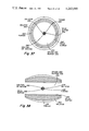
- FIG. 35 is a schematic illustration of the baisc geometry for fast spherical liner implosion of a structured microsphere.
- FIG. 36 is a schematic illustration of the basic geometry for fast cylindrical liner implosion of a structured microsphere.
- FIG. 37 is a schematic illustration of a cross-sectional view of a fast spherical liner and a structured microsphere.
- FIG. 38 is a schematic illustration of a cross-sectional view of a fast cylindrical liner and a structured microsphere.
- the anomalous transfer of relativistic electron beam energy and momentum into thermal and directed plasma energy, respectively, is nonclassical and, therefore, the strength of the nonlinear state of the microinstabilities depends upon a large number of factors.
- the characteristic nonuniform energy deposition of the collective interaction is utilized to concentrate the energy in the plasma.
- the optimized relativistic electron beam-plasma interaction is a power density multiplication process. Since energy is being transferred from relativistic beam electrons to nonrelativistic electrons in the plasma, conservation of energy and momentum require that the interaction both heat and drive a localized axial current in the plasma. The driven axial current, in turn, generates an azimuthal magnetic field.
- the physical configuration is similar to a nonuniform denze Z pinch in which the azimuthal magnetic field provides confinement.
- the heating and confinement are anomalous in character.
- the azimuthal magnetic field leads to a directed heat flow towards the axis of the device.
- the kilovolt plasma is used to drive a hierarchy of inertial confinement devices according to the present invention.
- anomalous resistive heating The basic idea behind anomalous resistive heating is that a ⁇ / ⁇ >1 beam cannot propagate since its self-magnetic field energy exceeds its particle energy. But, when such a beam is injected into a plasma, it neutralizes this characteristically large self-magnetic field energy by inducing a plasma return current.
- the relationship between the plasma and beam species in velocity space for a magnetically neutralized beam is shown in FIG. 4. Due to the relative drift between the plasma electron and ion species, ion-acoustic and/or ion-cyclotron waves are generated, as illustrated in FIG. 4 by the dashed lines. Such microturbulence is known to manifest itself as anomalous resistance. Thus, the plasma is heated at a rate
- W p is the plasma energy density
- ⁇ * is the anomalous resistivity
- J p is the plasma return current density
- relaxation heating according to method (a) results from the relative drift between the relativistic beam electrons and plasma electrons. Optimally, these instabilities take the form of electron bunching at a wavelength of
- n e is the plasma electron density.
- the characteristic relationship between the plasma and beam species for optimized relaxation heating is illustrated in FIG. 5. Locally, the net current I net within the beam channel can exceed the beam current I b , in contrast to the magnetically neutralized beam where I net ⁇ 0 within the beam channel. As stated, this current multiplication is a consequence of momentum conservation, and is a very localized phenomenon. The location of the unstable spectrum for these instabilities is indicated by dashed lines in FIG. 5.
- the present invention in contrast to prior art plasma heating techniques takes advantage of the natural characteristics of two extremely powerful microinstabilities, i.e., the two-stream and upper-hybrid instabilities illustrated in FIG. 5, to locally heat a small volume of plasma in the form of an annulus to kilovolt temperatures.
- the instabilities are created by the relative drift between the relativistic beam electrons and target plasma electrons.
- the dominant factors in determining the strength of the instabilities are (1) beam temperature along a streamline, and (2) the wavelength of the instabilities relative to the radial dimension of the target plasma.
- beam temperature along a streamline occurs primarily from the passage of the relativistic electrons of the beam through the foil dividing the low-density plasma and diode vacuum.
- the effect of the foil can be made negligible by (1) increasing the electron energy, (2) reducing the thickness of foil, or (3) reducing the effective Z of the foil material.
- a high-voltage, i.e., exceeding 3 MeV electron beam can, in fact, penetrate a number of foils and still deposit its energy efficiently in the high-density plasma.
- the wavelength of the instabilities are small compared to the radial dimensions of the plasma.
- the instantaneous deposition rate can vary, the nonlinear evolution of the instability functions to relax the beam distribution in both angle and energy, resulting in an efficient coupling of beam energy to the plasma.
- S ⁇ 2 ⁇ (n b /2n e ) 1/3 is the strength parameter
- F is a function depending upon the foil thickness and material
- n b is the beam density
- n e is the plasma electron density
- FIG. 8 illustrates results of an additional experiment showing propagation distance in a high-density plasma with various foil thicknesses and anode-cathode gap spacing.
- a 7 MeV beam was injected into a 43 cm long, 0.4 torr H 2 gas target. No external magnetic field was present.
- the beam energy transmitted to a calorimeter located 43 cm from the anode foil was measured as a function of the anode-cathode gap spacing and anode foil thickness.
- Anode foils of 25.4 ⁇ m kapton and 25.4 ⁇ m, 76.2 ⁇ m, 127.0 ⁇ m, and 304.8 ⁇ m titanium were used.
- a more detailed one-dimensional analysis indicates that not all the beam electrons act coherently during the bunching process, since their individual responses vary with energy. Basically, this is due to phase mixing. Denoting ⁇ as the coupling coefficient, the one-dimensional analysis yields
- a possibly more serious source of random motion is electron emission from the cathode shank and lack of beam equilibrium at the emission surface.
- this source of random motion can also be reduced to a negligible level.
- Tyical values for the foil scattering function (F) are given in the table of FIG. 9. It follows that increasing ⁇ and decreasing the foil's effective thickness results in the factor exp(- ⁇ S/F) approaching zero. Thus, the beam can penetrate a closed container and retain a high coupling efficiency to the enclosed target plasma.
- the transverse motion associated with the beam self-fields comprises an effective temperature. If no external magnetic field is present and the beam is injected into a plasma in order to obtain equilibrium, such ordered motion can evolve into random motion. However, for the optimized interaction, the coherence length of the beam is long relative to the deposition length. Thus, high-voltage, low ⁇ / ⁇ beams in a focused flow configuration can interact strongly with a plasma, provided the plasma begins at the anode foil and ⁇ n/n b ⁇ 1.
- the wavelength associated with the streaming instabilities is very short compared to the radial dimensions of the beam and plasma, Eq. (2).
- the optimal nonlinear evolution of the instability is highly two-dimensional, and once initiated is extremely difficult to degrade.
- the formation of plasma hydrodynamic gradients and beam pinching due to current multiplication results in the instantaneous deposition rate varying in time. Such a time variation is not monotonic, however.
- ⁇ p is the target plasma frequency and c is the speed of light. This is orders of magnitude shorter than the classical range of megavolt electrons in a 10 17 -10 20 cm -3 density plasma.
- n b ( ⁇ ) is determined from one-dimensional, relativistic foil diode result, such as disclosed by H. R. Jory and A. W. Trivelpiece, J. Appl. Phys. 40, 3924 (1969),
- the diode gap spacing is d and the adiabatic compression ratio is M.
- the dimensionless parameter ⁇ ( ⁇ ) is shown for given values of the plasma electron density n e in FIG. 10. Because wave e-fold from noise, most of the beam energy is actually deposited over a length shorter than L N by a factor of 2 to 3.
- the characteristic nonuniform energy deposition of the collective mechanisms, two-stream and upper-hybrid instabilities, is shown in FIG. 6, for both the one- and two-dimensional interactions. According to the present invention, this nonuniform deposition property is utilized to concentrate energy deposited into the plasma from the relativistic electron beam, as opposed to prior art experimentation wherein energy is allowed to dissipate its explosive character by expansion into a much larger volume of plasma.
- the first approach is a direct use of the plasma as the source by confining its energy for a sufficient length of time as disclosed in copending applicaton Ser. No. 882,024 entitled "Device and Method for Electron Beam Heating of a High Density Plasma” filed Feb. 28, 1978 by Lester E. Thode.
- a solid relativistic electron beam penetrates a 3 cm 3 to 50 cm 3 gas filled container, and transfers a fraction of its energy and momentum to the enclosed gas. Conservation of energy and momentum requires that the beam both heat the plasma and drive a large axial plasma current. The presence of the large axial current, in turn, initiates additional plasma ion heating and confinement. This configuration is similar to a dense Z-pinch.
- FIG. 11 discloses a schematic diagram of the major components of a device which uses the high-energy density plasma as a source.
- an annular relativistic electron beam is utilized to penetrate a 3 cm 3 to 50 cm 3 gas filled container, and to transfer a fraction of its energy and momentum to the enclosed gas.
- conservation of energy and momentum causes the beam to both heat the plasma and drive a large axial plasma current.
- the heated plasma is annular, the large axial current leads to directed heat flow towards the interior of the annular region, where a fast liner is disposed which is engulfed and driven inwardly by hot electrons to implode a structured microsphere.
- the fast liner functions as a power multiplier, which is cylindrical, spherical, or ellipsoidal in shape.
- the liner By adjusting the electron heating rate and plasma density, the liner can be driven by either ablation or exploding pusher to implode the structured microsphere. Also, control of the driving electron temperature and distribution is accomplished by varying the plasma density and magnitude of the external magnetic field.
- FIG. 12 A conceptual diagram of the major components of a system to utilize a high-energy density plasma to drive power multiplication conversion devices is shown in FIG. 12.
- FIGS. 11 and 12 Many modifications and variations of the configurations shown in FIGS. 11 and 12 are possible. For example, various applications of the concept do not require the use of a low-density gas chambers 52 and 94, modulators 38 and 80, drift tubes and adiabatic compressors 36 and 78, or multigap accelerators 32 and 74. With advances in relativistic electron beam technology, external magnetic field sources 70 and 110, preionizers 62 and 64, 104 and 106, and windows 54 to 60, and 96 to 102 can be eliminated. With annular beams, multiple beam systems are possible, as depicted in FIGS. 13 through 15. For multiple beam systems, the energy deposition regions do not overlap, allowing such systems to drive larger power multiplication devices.
- a high-voltage, high-current density relativistic electron beam is required for the reasons set forth above.
- a number of high-impedance generators are in use, such as the PI23-100, PI15-90, PI14-80, and PI950 which are schematically illustrated in FIG. 16.
- PI refers to the Physics International Company
- the first number is the diameter of the Blumlein in feet
- the second number is the number of stages in the Marx generator.
- the generators are relatively compact in size for the energy delivered.
- the time to design and build such generators is relatively short.
- the PI14-80 was recently designed and built in eight months.
- the cost of the technology is relatively inexpensive.
- high-impedance generators are composed of five basic components.
- a dc charging system 116 is used to charge the Marx generator 118, which is the primary energy storage component.
- the Marx generator 118 consists of a large number of stages which are charged in parallel and discharged in series using spark gap switches.
- FIG. 19 schematically illustrates the electrical equivalent of a Marx stage which consists of two capacitances 126 and 128 connected in series with a center ground to allow positive and negative dc charging.
- a Blumlein 120 is essentially two coaxial transmission lines 130 and 131 connected in series with the diode impedance 134 Z D . Physically, the Blumlein appears as three concentric, annular conductors. This folded configuration is used to reduce the spatial dimension of the Blumlein.
- the center conductor 132 is charged through an inductor 138 having an inductance L c which appears as a short. Once charged, the switch 136 is closed and the transmission line 131 begins to discharge with a pulse propagating toward the diode 134.
- the final component is the diode 124, which can be either foil or foilless. Foil diodes suffer rapid impedance collapse when the current density exceeds 20 kA/cm 2 . The physics of this problem has not, however, been considered in a systematic fashion and current densities up to 100 kA/cm 2 should be obtainable with improved vacuum systems.
- Foilless diodes are naturally suited for the device of the present invention since annular beams are readily produced at high current densities. However, the operation and flow characteristics of such diodes could be significantly advanced. A detailed discussion of the potential of the foilless diode is disclosed in Los Alamos Scientific Report LA-7169-P by Lester E. Thode entitled "A Proposal for Study of Vacuum Adiabatic Compression of a Relativistic Electron Beam Generated by a Foilless Diode.”
- Pulsed high-current electron beams with particle energy exceeding 20 MeV can be produced with a multigap accelerator, as schematically illustrated in FIG. 21.
- the multigap accelerator is basically a linear accelerator with radial transmission lines or Blumleins providing energy to the accelerating gaps 146.
- Radial lines 140 are composed of coaxial disk or cone conductors which are stacked in series.
- the accelerator is amenable to mass production, probably at a cost of less than $5/joule delivered.
- the development time of a 200 to 800 kJ, 5 to 20 TW, 10 to 100 cycle per second prototype accelerator is less than five years.
- the injector 144 for such an accelerator can be the high-current electron beam generator disclosed infra, or the first accelerating stage of the accelerator. Fabrication of such accelerators is disclosed by A. I. Pavlovskii et al., Sov. Phys. - Dokl. 20, 441 (1975), in an article entitled "Multielement Accelerators Based on Radial Lines.”
- the relativistic electron beams 34 and 76 propagate along the vacuum drift tube and adiabatic compressors 36 and 78 to the modulators 38 and 80.
- External solenoidal magnetic field sources 40 and 82 generate a magnetic field in the generator diode, accelerator, drift tube, and modulator regions to ensure a laminar flow beam equilibrium.
- the strength of the external magnetic field can be increased along the direction of beam propagation to produce adiabatic beam compression.
- Modest compression ratios can reduce the beam radius a factor of 2 to 3, while preserving a laminar flow equilibrium, provided the compression is carried out in vacuum.
- Vacuum systems 42 and 84 maintain the required vacuum.
- Modulators 38 and 80 constitute an inner portion of the vacuum drift tubes 36 and 78 and are formed by a periodic structure or dielectric layer along the direction of beam propagation. Alternatively, a rippled magnetic field could be utilized to weakly bunch the beam.
- the purpose of modulators 38 and 80 is to provide an enhanced narrow band noise level (very weak modulation) at a wavelength and phase velocity slightly below the natural wavelength and phase velocity of the instability in the target plasma.
- the beam energy loss is determined by ⁇ (modulated) shown in FIG. 22.
- the coupling efficiency is then increased to ##EQU2## where ⁇ 1.0 to 1.3 based upon analysis of the modulated interaction. Physically, the modulation leads to an enhanced strength parameter( ⁇ S). The modulation also reduces the effect of foil scattering and collisions on the interaction.
- the low-density gas chambers 52 and 94 provide isolation between the replaceable target plasma containers 66 and 108 and modulators 38 and 80, drift tube and adiabatic compressors 36 and 78, accelerators 32 and 74, and generators 30 and 72 of FIGS. 11 and 12, respectively.
- the electron density in the ionized low-density plasma channels 46 and 88 is typically close to the relativistic electron beam density, whereas in the target plasmas 68 and 112 the electron density is 4 to 6 orders of magnitude above the beam density.
- the low-density gases 50 and 92 comprise either H 2 , He, Ar, N 2 or residual gas associated with the previous operation of the system.
- Foils 44 and 86 provide isolation between the vacuum modulators 38 and 80 and the low-density plasma channels 46 and 88, and convert a small fraction of the rising beam impulse into Bremsstrahlung radiation which is directed predominantly along the direction of beam propagation.
- the isolation function is provided by a layer of metal (titanium, aluminum, or beryllium), graphite, or plastic, such as mylar (C 10 H 8 O 4 ), kapton (C 22 H 10 N 2 O 5 ), or polycarbonate.
- a layer of plastic impregnated with high Z atoms, a fine mesh high Z wire screen with a very high optical transparency, or a high Z aperturing layer can be used to provide the Bremsstrahlung radiation.
- Bremsstrahlung radiation generated in this manner aids in the creation of low-density plasma channels 46 and 88 for beam propagation through the low-density gases 50 and 92.
- foils 44 and 86 can be eliminated in favor of strong differential pumping of the modulator regions 38 and 80.
- Foils 48 and 90 provide isolation between the low-density plasma channel 46 and the dense target plasma and are constructed in a fashion similar to foils 44 and 86. Foils 48 and 90 also act to initiate the collective interaction and generate Bremsstrahlung radiation for partial ionization of the dense plasma target to assist or replace preionizers 62 and 64, 104 and 106.
- the self-fields of the beam are shorted out so that an external magnetic field is not required to achieve beam equilibrium.
- the beam can be ballistically guided through low-density plasma channels 46 and 88 to the plasma target.
- the overall efficiency of the system is enhanced by the presence of external magnetic field sources 70 and 110.
- external magnetic field sources 70 and 110 provide increased stabilization of the relativistic electron beam within low-density plasma channels 46 and 88, respectively.
- Preionizers 62 and 64, 104 and 106 provide full ionization of target plasmas 68 and 112, respectively.
- Any number of devices for creating a fully-ionized gas such as discharge tubes, channel forming wires, various lasers including electron beam driven free electron lasers, plasma guns, microwave generators, or low-energy particle beams, can be used.
- the laser is the best device for creating a low-temperature, fully-ionized plasma in the 10 17 to 10 20 electrons/cm 3 density region.
- windows 54 to 60 and 96 to 102 are positioned in the low-density gas chambers 52 and 94 and target plasma containers 66 and 108, respectively.
- a fully-ionized target density of 8 ⁇ 10 18 to 10 20 electrons/cm 3 a 0.1 ⁇ s to 2.0 ⁇ s, 0.2 kJ to 10 kJ HF laser, or a number of smaller HF lasers, can be used as preionizers 62 and 64, 104 and 106.
- a 0.1 ⁇ s to 2.0 ⁇ s, 0.2 kJ to 3 kJ CO 2 laser, or a number of smaller CO 2 lasers, are appropriate for fully ionizing gases with densities less than 8 ⁇ 10 18 electrons/cm 3 .
- the combination of Bremsstrahlung radiation produced at foils 48 and 90, direct impact ionization by the beam, avalanche, and the initial collective interaction is capable of fully ionizing the target plasma.
- the beam requirements are more stringent when the relativistic beam provides both ionization and heating of the target plasma.
- the anomalous pinch is the simplest mode of operation and provides a basis for employment of the fast liner device comprising the present invention.
- the relativistic electron beam target is a simple gas-filled container of DT, DD or HB.
- the anomalous pinch intrinsically requires a very high-density plasma of at least 10 19 electrons/cm 3 .
- the anomalous pinch can be operated as a target for an intense deuterium beam generated by the rapidly developing pulse power light-ion beam technology.
- the plasma electron temperature can be elevated sufficiently to reduce the cross section for deuterium beam energy absorption by target plasma electrons.
- the probability of survival of trapped energetic deuterium ions to undergo fusion with the plasma deuterium and tritium ions is significantly enhanced.
- intense neutron pulses can be produced using present pulse power technology.
- a moderate Z gas or a mixture of H 2 and high Z gas with an electron density of 10 17 -10 19 cm -3 can be used as the target plasma 68 of the device of FIG. 11 to produce radiation.
- beryllium windows in the target plasma container 66 are used and the low-density gas chamber 52 is eliminated.
- Such a tunable radiation source is suitable for a variety of applications.
- the device of FIG. 11 operates by applying the relativistic electron beam 34 to low-density gas chamber 52 such that beam 34 penetrates foil 48 with negligible scattering and initiates convective wave growth such that the waves e-fold until saturated through nonlinear trapping of the beam electrons. Since the nonlinear waves are not normal plasma modes, they are absorbed into the plasma very rapidly through nonlinear mode beating. Actually, this nonlinear mode beating acts throughout the entire interaction and keeps the level of electric field energy relatively low compared with the energy transferred from the beam to the plasma. The presence of the foil 48 thus ensures that the beam energy is deposited at a specified location within the target plasma container 66, as opposed to moving upstream.
- the beam Since energy and momentum are being transferred from relativistic electrons 34 to nonrelativistic electrons within the target plasma 68, the beam both heats and drives an axial current in the target plasma. The presence of the axial current, in turn, initiates plasma energy confinement through the generation of a azimuthal magnetic field similar to a Z pinch. Taking into account increased internal pressure resulting from the nonohmic process, an equilibrium pinch configuration is formed with currents in the multi-megampere range, with significant reduction in heat conduction losses. Relative to the typical classical Z-pinch, the generation of the anomalous pinch is considerably faster.
- the anomalously generated azimuthal magnetic field 150 and heated plasma column 148 is illustrated in FIG. 23.
- the axial nonuniformity in the azimuthal magnetic field strength of azimuthal magnetic field 150 is similiar to the energy deposition illustrated in FIG. 6.
- Primary energy loss from the anomalous pinch is indicated by arrows.
- FIG. 24 is a schematic illustration of the arrangement schematically disclosed in FIG. 11 and disclosed in the above referenced copending application for producing an anomalous pinch.
- relativistic electron beam generator 152 produces a solid relativistic beam 154 which propagates through the vacuum tube and adiabatic compressor 156 and adjacent modulator 158.
- the relativistic electron beam 154 then penetrates foil 160, passes through the low-density plasma channel 162, penetrates foil 164, and anomalously transfers a fraction of its energy and momentum to the target plasma 170 to generate the anomalous pinch illustrated in FIG. 23.
- Windows 172 and 174 allow the laser ionization beam 178 to penetrate the target plasma container 168 and low-density gas chamber 166.
- a salt or sapphire window is used for CO 2 or HF lasers, respectively.
- An ionization beam intensity of 10 9 to 10 10 watts/cm 2 is sufficient to fully ionize the plasma.
- a fully-ionized plasma with sufficient axial uniformity can be formed using the configuration shown in FIG. 24.
- the laser energy is transferred to the target plasma through inverse Bremsstrahlung. Consequently, the target plasma exhibits a slightly decreasing gradient along the direction of propagation of the relativistic electron beam 154.
- Such a decreasing gradient tends to increase the strength of the deposition, since its effect on the nonlinear dynamics is similar to premodulation.
- the ability of the streaming instabilities to counteract self-consistent plasma hydrodynamic gradients is related to this dynamic effect.
- FIG. 25 is an alternative arrangement in which two lasers 208 and 210 apply ionization beams 212 and 214 transverse to the axis of the relativistic electron beam 182.
- Windows 204 and 206 in the low-density gas chamber 194 and windows 200 and 202 in the target plasma container 196 allow passage of the ionization beams to the target plasma 198.
- FIG. 26 is a schematic end view of an additional alternative arrangement utilizing three lasers 234, 236, and 238 which produce ionization beams 240, 242 and 244.
- Windows 228, 230 and 232 in the low-density gas chamber 216 and windows 222, 224 and 226 in the target plasma container 218 provide ionization beams 240, 242 and 244 access to the target plasma 220.
- the advantage of the arrangement shown in FIG. 26 is that lasers 234, 236 and 238 are arranged in an off-axis position such that laser beams 240, 242 and 244 are not directed at other lasers.
- the preceding laser configurations are also appropriate for systems which use the high-energy density plasma to drive a fast liner to implode a structured microsphere according to the present invention, schematically shown in FIG. 12. Since the laser intensity is quite low, the hot electron spectrum generated by such a beam interacting directly with a power multiplication device is negligible.
- the components of FIG. 11 and their operation are identical to the components of FIG. 12 with the exception of the target plasma container 66 and relativistic electron beam 34. Similarly, the deposition of electron beam energy in the target plasma 112 occurs in the same manner described with respect to FIGS. 5, 6, 11 and 22 to 26. Therefore, the remaining disclosure of FIGS.
- liners high explosives or magnetically driven thin, cylindrical metallic shells have been referred to as liners.
- These hybrid devices incorporate concepts common to both magnetic and inertial confinement of plasma. Liners have been used to compress magnetic fields, compress and heat magnetically confined plasmas, and generate radiation. According to the present invention, this type of power multiplication device can be generalized to include spherical and ellipsoidal shapes. Since the liners are multilayer in design, they are much like laser fusion pellets.
- FIGS. 27 and 28 A configuration suitable for driving fast spherical or cylindrical liners, such as disclosed in the above referenced copending application Ser. No. 9,703 entitled “Device and Method for Relativistic Electron Beam Heating of a High-Density Plasma to Drive Fast Liners" filed Feb. 5, 1979 by Lester E. Thode, is shown in FIGS. 27 and 28, respectively.
- a single laser ionization beam 252 entering through window 254 is used.
- Multiple laser ionization configurations, as shown in FIGS. 25 and 26, may be employed to obtain full ionization.
- the use of lasers for preionization lowers the relativistic electron beam technology requirements as disclosed above. Thus, the laser ionization sources should be considered as optional.
- annular relativistic electron beam 260 which corresponds to beam 76 produced by the device of FIG. 12, penetrates the initiation foil 246, which also acts as an end plug to contain the low-temperature plasma or gas. As the voltage and current density rise, the anomalous coupling coefficient increases to its optimal value, and the beam transfers a large fraction of its energy and momentum to the annular plasma region 258.
- the beam driven azimuthal magnetic field 256 directs the annular plasma thermal energy to the fast spherical liner 250 or fast cylindrical liner 262.
- the source of the azimuthal magnetic field 256 is the result of an axial current flow in the annular plasma 258, magnetic field 256 is not present in the vicinity of the fast spherical liner 250 or fast cylindrical liner 262.
- the presence of an axial external magnetic field generated by external magnetic field source 110 shown in FIG. 12, can be used to increase the anomalous coupling coefficient.
- the annular plasma column 258 is very high beta, the external magnetic field produced by source 110 is excluded during operation.
- the radial wall of the plasma target container 248 is sufficiently thick to ensure magnetic flux containment and sufficiently massive to provide radial inertial confinement (tamper) on the relativistic electron beam time scale, i.e. ⁇ 100 ns.
- radial energy loss to the container wall is limited by both the azimuthal magnetic field 256 and excluded external magnetic field produced by source 110.
- Heat conduction is limited axially on the beam time scale by the lower axial temperature gradient, azimuthal magnetic field 256, and self-mirroring of the external magnetic field 110.
- the geometry takes advantage of anomalous coupling and classical heat conduction to rapidly and efficiently remove energy from the relativistic electron beam 260 and transport it to the fast liner.
- FIGS. 29 and 30 A cross-sectional view of the basic configuration with dual laser ionization beams 268 and 270, 282 and 284 for driving fast liners as disclosed in the above referenced copending application is shown in FIGS. 29 and 30, respectively.
- windows 264 and 266, 278 and 280 are placed in the radial wall of the plasma container.
- the heated annular plasmas 274 and 286 drive the spherical and cylindrical fast liner to implosion by explosive or ablative means as disclosed previously.
- FIGS. 31 and 32 Detail of the fast spherical liner 250 and fast cylindrical liner 262 as disclosed in the above referenced application is shown in FIGS. 31 and 32, respectively.
- Each of the fast liners consists of ablators 292 and 298, pushers 294 and 300 and solid buffers 296 and 302.
- the ablator is boiled off through heat conduction, to propel the pusher and solid buffer to high-implosion velocity. Since the thermal conductivity of a plasma is a strong function of temperature, the rate at which energy is transported to the liner increases in time throughout the beam pulse. Thus, some natural shaping of the plasma driving source is obtained. Such shaping leads to stronger compression and heating of the gas fuel 272 and 288, as disclosed by R. J. Mason et al., Phys. Fluids 18, 814 (1975) and S. D. Bertke et al., Nucl. Fusion 18, 509 (1978).
- the ablators 292 and 298 of both the spherical and cylindrical liners are a low Z, low mass density material such as LiDT, Be, ND 3 BT 3 , boron hydride, or CDT.
- Pushers 294 and 300 are typically a higher Z and mass density material such as glass, aluminum, gold, or nickel. Plastic embedded with high Z atoms is also used.
- Solid DT or LiDT can be used for the solid buffers 296 and 302. Depending upon the desired implosion velocity and various stability considerations, the total mass of fast liner 250 and 262 varies from 1 to 100 milligrams.
- gas fuel 272 and 288 for both spherical and enclosed cylindrical liner may comprise DT, DD, DHe 3 , HLi 6 , or HB 11 whereas the target plasma 274 and 286 may comprise H 2 , He, DT, DD, or other low Z gas.
- An ellipsoidal shaped liner can also be used.
- FIG. 33 illustrates another embodiment utilizing a fast liner.
- a solid beam penetrates foil 320 to form an anomalous pinch 318 within the cylindrical liner 262, which is, in turn, driven by an annular beam entering through foil 304.
- Deflector 306 provides initial ionization in the anomalous pinch region 318.
- the cylindrical liner 262 implodes upon the plasma 318 to enhance compression and burn.
- Target geometry utilizing two annular relativistic electron beams to drive a spherical liner 250 is schematically illustrated in FIG. 34.
- beam deflection is minimized as beams 326 and 328 pass through the beam driven azimuthal magnetic field regions, as indicated in FIG. 14.
- the approach of obtaining an intense radiation, neutron and/or alpha particle source is to use a high-density, multi-kilovolt relativistic electron beam produced plasma to drive a fast liner, which then produces an intense, shaped energy pulse suitable for imploding a structured microsphere such as disclosed R. J. Mason, Phys. Fluids 18, 814 (1975) and Los Alamos Scientific Report LA-5898-MS (October 1975), S. D. Bertke et al., Nucl. Fusion 18, 509 (1978), and G. S. Fraley et al., Phys. Fluids 17, 474 (1974).
- a microsphere can be filled with either DT, DD, DHe 3 HLi 6 , or HB 11 , for example.
- FIGS. 35 and 36 The basic geometry of the approach of the present invention is illustrated in FIGS. 35 and 36, for a single laser ionization beam 340 entering through window 342.
- the multiple laser ionization configurations as shown in FIGS. 25 and 26 can also be used.
- the use of lasers for preionization lowers the relativisitc electron beam technology requirements. Therefore, the laser ionization sources should be considered as optional.
- An annular relativistic electron beam 344 penetrates the initiation foil 346, which also acts as an end plug to contain the low-temperature plasma. As the voltage and current density rise, the anomalous coupling coefficient increases to its optimal value, and the beam transfers a large fraction of its energy and momentum to the annular plasma region 348.
- the beam driven azimuthal magnetic field 350 directs annular plasma 348 thermal energy to the fast spherical liner 352 of FIG. 35, or fast cylindrical liner 354 of FIG. 36.
- the azimuthal magnetic field 350 is not present in the vicinity of the fast spherical liner 352 or fast cylindrical liner 354.
- the presence of an axial external magnetic field generated by source 110 of FIG. 12 can be used to increase the anomalous coupling coefficient.
- the annular plasma column 348 and plasma engulfing the liner are very high beta, the external magnetic field generated by source 110 of FIG. 12 is rapidly excluded.
- the radial wall of the plasma target container 356 is sufficiently thick to ensure magnetic flux containment and sufficiently massive to provide radial inertial confinement (tamper) on the relativistic electron beam time scale, i.e. ⁇ 100 ns.
- radial energy loss to the container wall is limited by both the azimuthal magnetic field 350 and excluded external magnetic field generated by source 110 of FIG. 12.
- Heat conduction is limited axially on the beam time scale by the lower axial temperature gradient, azimuthal magnetic field 350, and self-mirroring of the external magnetic field generated by source 110.
- the geometry takes advantage of anomalous coupling and classical heat conduction to rapidly and efficiently remove energy from the relativistic electron beam 344 and transport that energy to the fast liners 352 and 354.
- the fast liners 352 and 354 consist of ablators 360 and 362, pushers 364 and 366, and solid buffer 368 or 370.
- the ablator is boiled off through heat conduction, to propel the pusher and solid buffer to high implosion velocity.
- the ablators 360 and 362 are low Z, low mass density material such as LiDT, Be, ND 3 BT3, boron hydride, or CDT.
- Pushers 364 and 366 are typically a higher Z and mass density material such as glass, aluminum, gold, nickel or plastic embedded with high Z atoms. Solid DT or LiDT can be used for solid buffers 368 and 370.
- the total mass of fast liners 352 and 354 illustrated in FIGS. 37 and 38, respectively is from 1 milligram to 100 milligrams.
- the driver gas 372 and 374 of FIGS. 37 and 38, respectively may comprise DT, DD, or higher Z gas such as N 2 , Ar, and Kr.
- the present invention therefore provides a device and method for driving a fast liner with a hot plasma to, in turn, drive a structured microsphere to implosion.
- natural pulse shaping generates high implosion velocities to generate energy in the form of radiation, neutrons, and/or alpha particles.
- the present invention provides efficient deposition of beam energy to heat the plasma and drive the fast liner to implode the microsphere.
- the implosion therefore generates high-intensity radiation, neutrons, and/or alpha particles utilizing currently available technology.
Priority Applications (4)
| Application Number | Priority Date | Filing Date | Title |
|---|---|---|---|
| US06/009,702 US4263095A (en) | 1979-02-05 | 1979-02-05 | Device and method for imploding a microsphere with a fast liner |
| GB8011606A GB2073474A (en) | 1979-02-05 | 1980-04-08 | Plasma device |
| FR8008813A FR2481050A1 (fr) | 1979-02-05 | 1980-04-18 | Procede et dispositif d'implosion d'une microsphere avec une enveloppe rapide |
| DE19803017126 DE3017126A1 (de) | 1979-02-05 | 1980-05-05 | Verfahren und vorrichtung zum implodieren eines mikrobereichs mittels eines schnell-laufrohrs |
Applications Claiming Priority (1)
| Application Number | Priority Date | Filing Date | Title |
|---|---|---|---|
| US06/009,702 US4263095A (en) | 1979-02-05 | 1979-02-05 | Device and method for imploding a microsphere with a fast liner |
Publications (1)
| Publication Number | Publication Date |
|---|---|
| US4263095A true US4263095A (en) | 1981-04-21 |
Family
ID=21739221
Family Applications (1)
| Application Number | Title | Priority Date | Filing Date |
|---|---|---|---|
| US06/009,702 Expired - Lifetime US4263095A (en) | 1979-02-05 | 1979-02-05 | Device and method for imploding a microsphere with a fast liner |
Country Status (4)
| Country | Link |
|---|---|
| US (1) | US4263095A (de) |
| DE (1) | DE3017126A1 (de) |
| FR (1) | FR2481050A1 (de) |
| GB (1) | GB2073474A (de) |
Cited By (20)
| Publication number | Priority date | Publication date | Assignee | Title |
|---|---|---|---|---|
| US4381280A (en) * | 1980-10-31 | 1983-04-26 | The United States Of America As Represented By The Secretary Of The Army | Method and device for producing nuclear fusion |
| USH75H (en) | 1983-11-23 | 1986-06-03 | The United States Of America As Respresented By The United States Department Of Energy | Nuclear diagnostic for fast alpha particles |
| US4875214A (en) * | 1985-08-08 | 1989-10-17 | William Denne | X-ray laser |
| US4937532A (en) * | 1988-09-14 | 1990-06-26 | The Regents Of The University Of California | Method of accelerating photons by a relativistic plasma wave |
| US5430776A (en) * | 1984-08-09 | 1995-07-04 | Stauffer; J. Christian | Fuel pellets for thermonuclear reactions |
| US6418177B1 (en) * | 1984-08-09 | 2002-07-09 | John E Stauffer | Fuel pellets for thermonuclear reactions |
| US20060198486A1 (en) * | 2005-03-04 | 2006-09-07 | Laberge Michel G | Pressure wave generator and controller for generating a pressure wave in a fusion reactor |
| US20060198484A1 (en) * | 2002-09-19 | 2006-09-07 | Conceicao Jose D | Propulsion motor |
| US20060198483A1 (en) * | 2005-03-04 | 2006-09-07 | General Fusion Inc. | Magnetized plasma fusion reactor |
| US20090303579A1 (en) * | 2005-01-07 | 2009-12-10 | Winterberg Friedwardt M | Amplification of Energy Beams by Passage Through an Imploding Liner |
| US20100098207A1 (en) * | 2008-10-16 | 2010-04-22 | Orhan Soykan | Method and device to produce heat and power |
| EP2572359A1 (de) * | 2010-05-17 | 2013-03-27 | Innoven Energy Partners | Trägheitsfusionsziele und kammern dafür |
| US8537958B2 (en) | 2009-02-04 | 2013-09-17 | General Fusion, Inc. | Systems and methods for compressing plasma |
| US20140023170A1 (en) * | 2011-11-07 | 2014-01-23 | Msnw Llc | Apparatus, systems and methods for fusion based power generation and engine thrust generation |
| US8891719B2 (en) | 2009-07-29 | 2014-11-18 | General Fusion, Inc. | Systems and methods for plasma compression with recycling of projectiles |
| US9609732B2 (en) | 2006-03-31 | 2017-03-28 | Energetiq Technology, Inc. | Laser-driven light source for generating light from a plasma in an pressurized chamber |
| US20170229194A1 (en) * | 2016-01-22 | 2017-08-10 | Innoven Energy, LLC | Simple and Robust Implosion of ICF Targets |
| US9741457B2 (en) | 2009-02-12 | 2017-08-22 | Msnw, Llc | Method and apparatus for the generation, heating and/or compression of plasmoids and/or recovery of energy therefrom |
| CN108615564A (zh) * | 2018-05-07 | 2018-10-02 | 中国工程物理研究院激光聚变研究中心 | 一种烧蚀状态下中z元素透射能流的测量靶及测量方法 |
| CN113130094A (zh) * | 2019-12-30 | 2021-07-16 | 核工业西南物理研究院 | 一种紧凑型激光吞食器 |
-
1979
- 1979-02-05 US US06/009,702 patent/US4263095A/en not_active Expired - Lifetime
-
1980
- 1980-04-08 GB GB8011606A patent/GB2073474A/en not_active Withdrawn
- 1980-04-18 FR FR8008813A patent/FR2481050A1/fr not_active Withdrawn
- 1980-05-05 DE DE19803017126 patent/DE3017126A1/de not_active Withdrawn
Non-Patent Citations (5)
| Title |
|---|
| J. Appl. Phys., vol. 44, No. 11, (11/73), pp. 4913-4919, Mather et al. * |
| Nuclear Fusion Suppl., (1977), vol. 2, p. 543, Thode II. * |
| Phys. of Fluids, vol. 19, No. 6, (6/76), pp. 831-848, Thode, Plasma Heating by Relativistic Electron Beams. * |
| Phys. of Fluids, vol. 20, No. 12, (12/77), pp. 2121-2127, Thode III. * |
| Sov. Tech. Phys. Lett., vol. 2, No. 1, (1/76), pp. 20-22, Kiselev et al. * |
Cited By (33)
| Publication number | Priority date | Publication date | Assignee | Title |
|---|---|---|---|---|
| US4381280A (en) * | 1980-10-31 | 1983-04-26 | The United States Of America As Represented By The Secretary Of The Army | Method and device for producing nuclear fusion |
| USH75H (en) | 1983-11-23 | 1986-06-03 | The United States Of America As Respresented By The United States Department Of Energy | Nuclear diagnostic for fast alpha particles |
| US5430776A (en) * | 1984-08-09 | 1995-07-04 | Stauffer; J. Christian | Fuel pellets for thermonuclear reactions |
| US6418177B1 (en) * | 1984-08-09 | 2002-07-09 | John E Stauffer | Fuel pellets for thermonuclear reactions |
| US4875214A (en) * | 1985-08-08 | 1989-10-17 | William Denne | X-ray laser |
| US4937532A (en) * | 1988-09-14 | 1990-06-26 | The Regents Of The University Of California | Method of accelerating photons by a relativistic plasma wave |
| WO1997001848A1 (en) * | 1993-08-16 | 1997-01-16 | Stauffer John E | Fuel pellets for thermonuclear reactions |
| US20060198484A1 (en) * | 2002-09-19 | 2006-09-07 | Conceicao Jose D | Propulsion motor |
| US20090303579A1 (en) * | 2005-01-07 | 2009-12-10 | Winterberg Friedwardt M | Amplification of Energy Beams by Passage Through an Imploding Liner |
| US8139287B2 (en) * | 2005-01-07 | 2012-03-20 | Board Of Regents Of The Nevada System Of Higher Education, On Behalf Of The University Of Nevada, Reno | Amplification of energy beams by passage through an imploding liner |
| US20100163130A1 (en) * | 2005-03-04 | 2010-07-01 | Michel Georges Laberge | Pressure wave generator and controller for generating a pressure wave in a medium |
| US20060198483A1 (en) * | 2005-03-04 | 2006-09-07 | General Fusion Inc. | Magnetized plasma fusion reactor |
| US20060198486A1 (en) * | 2005-03-04 | 2006-09-07 | Laberge Michel G | Pressure wave generator and controller for generating a pressure wave in a fusion reactor |
| US10002680B2 (en) | 2005-03-04 | 2018-06-19 | General Fusion Inc. | Pressure wave generator and controller for generating a pressure wave in a liquid medium |
| US9609732B2 (en) | 2006-03-31 | 2017-03-28 | Energetiq Technology, Inc. | Laser-driven light source for generating light from a plasma in an pressurized chamber |
| US20100098207A1 (en) * | 2008-10-16 | 2010-04-22 | Orhan Soykan | Method and device to produce heat and power |
| US10984917B2 (en) | 2009-02-04 | 2021-04-20 | General Fusion Inc. | Systems and methods for compressing plasma |
| US9875816B2 (en) | 2009-02-04 | 2018-01-23 | General Fusion Inc. | Systems and methods for compressing plasma |
| US8537958B2 (en) | 2009-02-04 | 2013-09-17 | General Fusion, Inc. | Systems and methods for compressing plasma |
| US9424955B2 (en) | 2009-02-04 | 2016-08-23 | General Fusion Inc. | Systems and methods for compressing plasma |
| US9741457B2 (en) | 2009-02-12 | 2017-08-22 | Msnw, Llc | Method and apparatus for the generation, heating and/or compression of plasmoids and/or recovery of energy therefrom |
| US11049620B2 (en) | 2009-02-12 | 2021-06-29 | Helion Energy, Inc. | Method and apparatus for the generation, heating and/or compression of plasmoids and/or recovery of energy therefrom |
| US9271383B2 (en) | 2009-07-29 | 2016-02-23 | General Fusion, Inc. | Systems and methods for plasma compression with recycling of projectiles |
| US8891719B2 (en) | 2009-07-29 | 2014-11-18 | General Fusion, Inc. | Systems and methods for plasma compression with recycling of projectiles |
| EP2572359A4 (de) * | 2010-05-17 | 2015-02-25 | Innoven Energy Partners | Trägheitsfusionsziele und kammern dafür |
| EP2572359A1 (de) * | 2010-05-17 | 2013-03-27 | Innoven Energy Partners | Trägheitsfusionsziele und kammern dafür |
| US20140023170A1 (en) * | 2011-11-07 | 2014-01-23 | Msnw Llc | Apparatus, systems and methods for fusion based power generation and engine thrust generation |
| US9524802B2 (en) | 2011-11-07 | 2016-12-20 | Msnw Llc | Apparatus and methods for fusion based power generation and engine thrust generation |
| US9082516B2 (en) * | 2011-11-07 | 2015-07-14 | Msnw Llc | Apparatus, systems and methods for fusion based power generation and engine thrust generation |
| US20170229194A1 (en) * | 2016-01-22 | 2017-08-10 | Innoven Energy, LLC | Simple and Robust Implosion of ICF Targets |
| US10475541B2 (en) * | 2016-01-22 | 2019-11-12 | Innoven Energy, LLC | Simple and robust implosion of ICF targets |
| CN108615564A (zh) * | 2018-05-07 | 2018-10-02 | 中国工程物理研究院激光聚变研究中心 | 一种烧蚀状态下中z元素透射能流的测量靶及测量方法 |
| CN113130094A (zh) * | 2019-12-30 | 2021-07-16 | 核工业西南物理研究院 | 一种紧凑型激光吞食器 |
Also Published As
| Publication number | Publication date |
|---|---|
| DE3017126A1 (de) | 1981-11-12 |
| FR2481050A1 (fr) | 1981-10-23 |
| GB2073474A (en) | 1981-10-14 |
Similar Documents
| Publication | Publication Date | Title |
|---|---|---|
| US4263095A (en) | Device and method for imploding a microsphere with a fast liner | |
| US4252607A (en) | Radiation source | |
| AU2007294621B2 (en) | Method and system for controlled fusion reactions | |
| US7482607B2 (en) | Method and apparatus for producing x-rays, ion beams and nuclear fusion energy | |
| Sahlin | Lawrence Livermore Laboratory | |
| Linhart | Very-high-density plasmas for thermonuclear fusion | |
| US4733133A (en) | Method and apparatus for producing microwave radiation | |
| Winterberg | Initiation of thermonuclear reactions by high-current electron beams | |
| US4248665A (en) | Device and method for relativistic electron beam heating of a high-density plasma to drive fast liners | |
| US4553256A (en) | Apparatus and method for plasma generation of x-ray bursts | |
| US4272319A (en) | Device and method for electron beam heating of a high density plasma | |
| Bystritskiĭ et al. | Intense ion beams | |
| Chuvatin et al. | Formation of a composite pinch | |
| Thode | Plasma device | |
| Golden et al. | The Generation and Application of Intense Pulsed Ion Beams: Ion beams are now being used to excite high-power gas lasers and to form field-reversed ion rings, and power levels may soon be high enough for applications in thermonuclear fusion programs | |
| US4381280A (en) | Method and device for producing nuclear fusion | |
| Yonas et al. | Relativistic Electron Beam Produced Plasmas | |
| Toepfer | Particle beam fusion | |
| Kolb | Uses of intense electron beams | |
| Thode | Anomalous intense driver (AID) concept | |
| Wang et al. | Prompt acceleration of the $\mu^+ $ beam in a donut wakefield driven by a shaped Laguerre-Gaussian laser pulse | |
| Chuvatin et al. | Spatial and temporal evolution of high-energy density plasmas in the composite pinch on GIT-4 generator | |
| CA2124364A1 (en) | Process and apparatus for radiation generation | |
| Krejčí | Gas-puff Z-pinch experiment | |
| Haas | General Principles of Inertial Confinement |