US4253624A - Welding wire dispenser - Google Patents

Welding wire dispenser Download PDF

Info

Publication number
US4253624A
US4253624A US06/137,839 US13783980A US4253624A US 4253624 A US4253624 A US 4253624A US 13783980 A US13783980 A US 13783980A US 4253624 A US4253624 A US 4253624A
Authority
US
United States
Prior art keywords
pallet
coil
column
wire
guide
Prior art date
Legal status (The legal status is an assumption and is not a legal conclusion. Google has not performed a legal analysis and makes no representation as to the accuracy of the status listed.)
Expired - Lifetime
Application number
US06/137,839
Inventor
Robert E. Colbert
Current Assignee (The listed assignees may be inaccurate. Google has not performed a legal analysis and makes no representation or warranty as to the accuracy of the list.)
National Standard Co
Original Assignee
Individual
Priority date (The priority date is an assumption and is not a legal conclusion. Google has not performed a legal analysis and makes no representation as to the accuracy of the date listed.)
Filing date
Publication date
Application filed by Individual filed Critical Individual
Priority to US06/137,839 priority Critical patent/US4253624A/en
Priority to ZA00806617A priority patent/ZA806617B/en
Assigned to NATIONAL-STANDARD COMPANY, A CORP. OF DE. reassignment NATIONAL-STANDARD COMPANY, A CORP. OF DE. ASSIGNMENT OF ASSIGNORS INTEREST. Assignors: COLBERT ROBERT E.
Priority to DE8181300822T priority patent/DE3173417D1/en
Priority to EP81300822A priority patent/EP0037632B1/en
Application granted granted Critical
Publication of US4253624A publication Critical patent/US4253624A/en
Assigned to FOOTHILL CAPITAL CORPORATION reassignment FOOTHILL CAPITAL CORPORATION SECURITY INTEREST (SEE DOCUMENT FOR DETAILS). Assignors: NATIONAL-STANDARD COMPANY
Anticipated expiration legal-status Critical
Assigned to NATIONAL STANDARD COMPANY reassignment NATIONAL STANDARD COMPANY RELEASE OF SECURITY INTEREST AND ASSIGNMENT Assignors: FOOTHILL CAPITAL CORPORATION
Expired - Lifetime legal-status Critical Current

Links

Images

Classifications

    • BPERFORMING OPERATIONS; TRANSPORTING
    • B65CONVEYING; PACKING; STORING; HANDLING THIN OR FILAMENTARY MATERIAL
    • B65HHANDLING THIN OR FILAMENTARY MATERIAL, e.g. SHEETS, WEBS, CABLES
    • B65H49/00Unwinding or paying-out filamentary material; Supporting, storing or transporting packages from which filamentary material is to be withdrawn or paid-out
    • B65H49/02Methods or apparatus in which packages do not rotate

Landscapes

  • Unwinding Of Filamentary Materials (AREA)

Abstract

A dispenser for coiled wire, particularly welding wire, which is supported upon a conventional wood pallet, the dispenser including a vertically disposed column having an upper end including a cover extending over the coil and nut means for tightly forcing the cover against the coil. A wire guide is rotatably mounted upon the column upper end rotating about the coil and dispensing wire therefrom, and the column lower end includes a hook bracket extending under pallet structure whereby tightening of the nut means pulls the bracket into a tight relationship with the pallet fixing the dispenser with respect to the coil and pallet, and simultaneously firmly maintaining the wire coil upon the pallet.

Description

This is a continuation of application Ser. No. 002,231 filed Jan. 10, 1979 and now abandoned.
BRIEF DESCRIPTION OF THE INVENTION
The invention pertains to dispensers for coiled wire, and particularly relates to dispensing coiled wire supported upon a pallet.
Wire is normally stored and transported while in coils, and the coils may be wound on reels or spools, boxed, banded, placed over spindles, or otherwise handled. Coils of welding wire used to supply electric welding equipment are often dispensed from coils as shown in U.S. Pat. No. 2,880,305. Welding wire can be most economically purchased in large coils, but previously, welding apparatus dispensers were not capable of handling large welding wire coils, and consequently, wire costs are greater than they would be if coils weighing several hundred pounds could be utilized. To handle such heavy coils it is necessary that the same be placed upon material handling devices, such as a pallet, which may be readily lifted, transported and positioned by a lift truck or similar material handling apparatus.
It is known to dispense wire from a coil by means of a guide rotatable about the coil axis, the wire being fed through the guide and into a stationary eye or conduit. Typical wire dispensers of this type are shown in U.S. Pat. Nos. 1,159,815; 1,834,159; 1,846,524; 2,286,460 and 2,319,828. Such devices, as shown in several of the aforementioned patents, include cover members which engage the upper portion of the spool and brake means control over run of the wire guide. The dispenser shown in U.S. Pat. No. 2,880,305 is particularly intended for dispensing welding wire, but this dispenser is used with relatively small wire coils.
In the past, a coiled wire dispenser for welding wire has not been available which could utilize large, economical wire coils. Usually, it is necessary to transfer the wire coil to specially built coil dispensing apparatus, and this necessity to handle the coil has limited the coil size as well as other handling and dispensing factors.
It is an object of the invention to provide a wire coil dispenser which may be employed with pallet supported wire coils directly, without necessitating the need to transfer the coiled wire from the pallet on which it is shipped.
A further object of the invention is to provide a coiled wire dispenser which may be directly installed upon a conventional pallet, and wherein installation of the dispenser tends to hold the wire coils on the pallet during use and augments the relationship between the pallet and its coiled wire load.
In the practice of the invention the dispenser includes a vertically oriented column having wire guide means rotatably associated with the column upper end through which the wire is removed from the coil exterior and fed in the desired direction. The column upper end also includes a cover engaging the coil upper surface and threads defined upon the column receive nut means for forcing the cover into firm engagement with the coil upper surface.
The lower end of the column includes a hook type bracket having a horizontal portion which is received between the lowermost horizontal slats of a conventional wood pallet. The horizontal hook portion is of a vertical dimension no greater than the vertical dimension of the lower pallet slats and the hook may be readily placed between the pallet slats and positioned as desired substantially coaxial with the wire coil.
Tightening of the nut means simultaneously forces the cover into engagement with the coil upper surface and draws the hook upwardly to produce a firm mechanical interconnection between the column and pallet. Thus, rotation of the nut means firmly positions the column relative to the wire coil and pallet, and the forces imposed upon the coil by the cover tend to maintain the shape and configuration of the wire coil as it is depleted, and prevents the wire coil from shifting relative to the pallet.
BRIEF DESCRIPTION OF THE DRAWINGS
The aforementioned objects and advantages of the invention will be appreciated from the following description and accompanying drawings wherein:
FIG. 1 is an elevational view, partially in section, illustrating a wire dispenser in accord with the invention as mounted upon a pallet,
FIG. 2 is a top plan view of FIG. 1, and
FIG. 3 is an enlarged, detail, elevational sectional view of the column hook as taken along Section III--III of FIG. 1.
DESCRIPTION OF THE PREFERRED EMBODIMENT
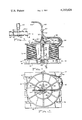
With reference to FIG. 1, a wire coil, such as of welding wire, generally indicated at 10 is mounted upon a conventional wood pallet 12. The coil 10 may weigh several hundred pounds, and is normally strapped or banded to the pallet for shipping purposes. The pallet includes a plurality of spaced parallel upper slats 14 nailed, screwed or otherwise affixed to three primary wood base members or elements 16 perpendicularly disposed to the slats 14. Such material handling pallets also usually include lower parallel slats 18 transversely disposed to base elements 16 and directly located below slats 14.
The dispenser includes a vertically extending column 20 of cylindrical configuration having an upper end 22 which is provided with exterior threads 24. The column lower end 26 includes a hook bracket 28 welded thereto, which will be later described in detail.
The column 20 includes a blind hole 30 coaxially bored therein rotatably receiving the guide support shaft 32.
A circular cover 34 rests upon the upper coils of coil 10 and the cover consists of a plurality of radially extending elements 36 affixed to a hub 38 and reinforced by a circular ring 40 and welded at their outer ends to circular rim 42 which extends slightly beyond the periphery of the wire coil. A nut 44 threaded upon threads 24 may be rotated by handles 46, and the washer 48 engaging the nut also engages the cover hub 38 wherein tightening of the nut 44 produces a downward force upon the cover 34.
The guide support shaft 32 supports a shaped conduit wire guide 50 which has an outlet at 52 coaxial with the shaft 32, and a wire inlet at 54 disposed adjacent the wire coil periphery. Bracing rod 56 extends toward the outer portion of the guide conduit 50 from the shaft 32, and a braking member 58 formed of friction material such as rubber, leather, or the like rotates with the guide and engages cover rim 42 to function as a brake to prevent overtravel of the guide as it is rotated during wire dispensing.
Hollow bearing structure generally indicated at 60 is located at the upper end of the guide conduit 50 at outlet 52 and supports the wire discharge conduit 62. Discharge conduit 62 is relatively stationary and dispenses the wire entering inlet 54 in the desired direction, such as toward the welding machine. The bearing structure 60 may take any conventional form, and it will be appreciated that as the wire 64 is pulled from the discharge conduit 62 the guide 50 will rotate about the axis of the column 20 and guide the wire being removed from the coil into the inlet 54.
The wire dispensing apparatus is mounted relative to the coil 10 and pallet 12 by the hook bracket 28 which is welded to the column lower end 26. The hook includes a vertically extending portion 66, and a substantially horizontally disposed portion 68 which extends below the central pallet base element 16. As will be appreciated from FIGS. 1 and 3, the vertical dimension of the hook portion 68 is no greater than the vertical dimension of the lower pallet slats 18 whereby the hook may be readily inserted under the central base element 16 even though the lower slats 18 are resting upon a solid floor. The hook 28 is of a width capable of being inserted between both the upper and lower slats 14 and 18, FIG. 3, and it will be appreciated that tightening of the nut 44 to force the cover 34 into engagement with the coil 10 also imposes an upward force on the hook to firmly engage the portion 68 with the associated base element 16. Thus, tightening of the nut 44 provides an effective mechanical interconnection between the wire dispensing column, cover, the wire coil and pallet.
The wire dispenser construction, and particularly the use of the hook bracket 28, permits the dispenser to be installed merely by lowering the column through the center of a strapped wire coil. The hook portion 68 may be inserted under the central base element 16 and the nut 44 tightened to firmly force the cover 34 against the coil. Thereupon, the banding straps binding the coil may be cut, if they have not already been severed, and the dispenser may be firmly installed prior to the coil being released from its transport banding.
The forces imposed upon the coiled wire by the cover 34 tend to maintain the coil configuration during use, and as many wire coils include an inner cylindrical spool or other similar member which defines the coil length the use of the cover aids in maintaining the coil configuration even until the coil is substantially depleted. Installation of the dispenser of the invention is readily accomplished by unskilled personnel, and the dispenser structure may be fabricated at relatively low cost.
It will be appreciated that various modifications to the inventive concept may be apparent to those skilled in the art without departing from the spirit and scope of the invention.

Claims (10)

I claim:
1. A dispenser for coiled welding wire supported upon a pallet having a plurality of spaced support slats affixed to a transversely disposed base element, comprising in combination, a column having a lower end and an upper end, a cover member mounted upon the column upper end adapted to engage and overlie the upper end of a coil of wire supported on the pallet, first connection means defined on said column upper end, second connection means cooperating with said first connection means axially displacing said cover on said column toward the pallet producing a vertical upward force on said column, rotatable wire guide means mounted on said column upper end for dispensing wire from the coil, and pallet attachment means defined upon said column lower end adapted to extend under pallet structure whereby operation of said first and second connection means fixes said column relative to the pallet and wire coil.
2. In a dispenser for coiled wire as in claim 1 wherein said pallet attachment means includes a hook adapted to extend under the pallet base element.
3. In a dispenser for coiled wire as in claim 2 wherein said hook includes a vertical portion disposed adjacent the pallet base element and a horizontal portion extending under the base element.
4. In a dispenser for coiled wire as in claim 3, said pallet having a plurality of lower spaced slats affixed to the underside of the base element, the vertical dimension of said hook horizontal portion being no greater than the vertical dimension of said lower spaced slats and said hook horizontal portion received between adjacent lower slats.
5. In a dispenser for coiled wire as in claim 1 wherein said first connection means comprises threads defined on said column upper end, and said second connection means comprises a threaded nut mounted upon said threads.
6. A dispenser for coiled welding wire supported upon a pallet having a plurality of spaced support slats affixed to a transversely disposed base element, the dispenser including a column having a lower end and an upper end, a cover member mounted upon the column adapted to engage and overlie the upper end of a coil wire, attachment means defined on said column upper end mounting said cover member thereon, and rotatable wire guide means mounted on the column upper end for dispensing wire from the coil, the improvement comprising pallet attachment means defined upon the column lower end adapted to attach directly to the pallet, said pallet attachment means comprising a bracket of a hook configuration having a substantially horizontal portion adapted to extend under the pallet base element, the pallet including a plurality of lower spaced slats affixed to the underside of the base element directly below the spaced support slats, the vertical dimension of said bracket horizontal portion being no greater than the vertical dimension of said lower spaced slats, said bracket including a vertical portion received between adjacent support slats.
7. Apparatus for dispensing a filamentary material from a stationary coil having a periphery and an axis, wherein the dispenser includes a guide support coaxially supported relative to the coil axis for rotation about the coil axis, the improvement comprising, a rotatable filament guide mounted upon the guide support for rotation therewith about the coil axis removing the filament from the coil, said guide including a hollow tubular member having a filament entrance end and a bearing supporting end concentric to the coil axis, a hollow bearing directly mounted upon said guide bearing supporting end concentric to the coil axis, and a relatively stationary tubular filament guide supported upon said bearing receiving filament from said rotatable guide and dispensing filament in a predetermined direction.
8. In an apparatus for dispensing a filamentary material as in claim 7, said rotatable guide comprising an elongated contoured tube, said guide filament entrance end being disposed adjacent the coil periphery.
9. Apparatus for dispensing a filamentary material from a stationary coil having an upper end, a lower end, a periphery and an axis wherein the coil lower end is supported upon a pallet, comprising, in combination, a column having an upper end and a lower end, coil engaging column support means mounted upon said column upper end, pallet engaging means defined upon said column lower end, a guide support rotatably mounted upon said column upper end, a tubular first guide mounted upon said guide support for rotation therewith having a filament entrance end and a bearing supporting end concentric to the coil axis, a hollow bearing mounted upon said guide bearing supporting end concentric to the coil axis, and a relatively stationary tubular filament guide supported upon said bearing receiving filament from said first guide and dispensing filament in a predetermined direction.
10. Apparatus for dispensing a filamentary material as in claim 9, said coil engaging column support means comprising a cover adapted to engage the coil upper end and force producing means for producing an upward axial force upon said column, said pallet engaging means including a hook member adapted to extend under a portion of the pallet.
US06/137,839 1980-04-07 1980-04-07 Welding wire dispenser Expired - Lifetime US4253624A (en)

Priority Applications (4)

Application Number Priority Date Filing Date Title
US06/137,839 US4253624A (en) 1980-04-07 1980-04-07 Welding wire dispenser
ZA00806617A ZA806617B (en) 1980-04-07 1980-10-28 Welding wire dispenser
DE8181300822T DE3173417D1 (en) 1980-04-07 1981-02-27 Dispenser for filamentary material, especially welding wire
EP81300822A EP0037632B1 (en) 1980-04-07 1981-02-27 Dispenser for filamentary material, especially welding wire

Applications Claiming Priority (1)

Application Number Priority Date Filing Date Title
US06/137,839 US4253624A (en) 1980-04-07 1980-04-07 Welding wire dispenser

Related Parent Applications (1)

Application Number Title Priority Date Filing Date
US06002231 Continuation 1979-01-10

Publications (1)

Publication Number Publication Date
US4253624A true US4253624A (en) 1981-03-03

Family

ID=22479253

Family Applications (1)

Application Number Title Priority Date Filing Date
US06/137,839 Expired - Lifetime US4253624A (en) 1980-04-07 1980-04-07 Welding wire dispenser

Country Status (4)

Country Link
US (1) US4253624A (en)
EP (1) EP0037632B1 (en)
DE (1) DE3173417D1 (en)
ZA (1) ZA806617B (en)

Cited By (25)

* Cited by examiner, † Cited by third party
Publication number Priority date Publication date Assignee Title
DE3203579A1 (en) * 1982-02-03 1983-08-18 Deutsche Gesellschaft für Wiederaufarbeitung von Kernbrennstoffen mbH, 3000 Hannover DEVICE FOR FEEDING A WIRE FROM A WIRE REEL TO A PROCESSING SITE
DE3417096A1 (en) * 1983-07-25 1985-02-07 National-Standard Co., Niles, Mich. WIRE SPOOL PACK
DE3501734A1 (en) * 1985-01-19 1986-07-24 Walter 7995 Neukirch Strauß Unwinding device for strand material present in roll form
US4657204A (en) * 1986-02-14 1987-04-14 Colbert Robert E Welding wire dispenser
US4660782A (en) * 1986-02-18 1987-04-28 Hegemann Kenneth J Portable reel for flexible conduits
US5120024A (en) * 1990-05-29 1992-06-09 The United States Of America As Represented By The Secretary Of The Navy Payout tension control system for reel mounted cable
US5465917A (en) * 1994-05-23 1995-11-14 Kosch; Delmar D. Welding wire dispenser with adjustable brake
US5634604A (en) * 1995-03-09 1997-06-03 Elco Enterprises, Inc. Wire dispenser with base anti-rotation lock
US5634610A (en) * 1995-06-23 1997-06-03 Walsh; Robert E. Portable wire dispenser
US5657935A (en) * 1995-12-07 1997-08-19 Elco Enterprises, Inc. Wire dispenser with adjustable base
US6439632B1 (en) 2001-01-02 2002-08-27 Jeff Webber Pallet lifting hook
US6550708B2 (en) * 2000-01-17 2003-04-22 Normand Messier Device for a wound wire that is relatively stiff
US20050258290A1 (en) * 2004-05-19 2005-11-24 Dieter Kuper System for handling welding wire and method of handling welding wire using the system
US20060226276A1 (en) * 2005-04-12 2006-10-12 Pierce Ronnie G Strand pack despooler
US20090057460A1 (en) * 2007-08-30 2009-03-05 Lincoln Global, Inc. Wire guide insert and method for drum package payoff
US20090057459A1 (en) * 2007-08-30 2009-03-05 Lincoln Global, Inc. Apparatus and method for tapered core drum package payoff
CN101903272B (en) * 2007-12-25 2012-07-18 住友轻金属工业株式会社 Unwinding method for level-wound coil
CN102648062A (en) * 2009-11-25 2012-08-22 美佐纸业股份有限公司 A device and a method for un-reeling of wire from a coil
WO2013074512A1 (en) * 2011-11-16 2013-05-23 Illinois Tool Works Inc. Floating dispensing mechanism for drum packed welding wire with a de-coil conduit
CN105947812A (en) * 2016-06-23 2016-09-21 浙江海洋大学 Marine cable winding frame
US10059561B2 (en) 2014-08-06 2018-08-28 Alcotec Wire Corporation Floating feed assist unit for the payoff of bulk packaged welding wire
CN109019141A (en) * 2018-06-13 2018-12-18 佛山舒宜添科技有限公司 A kind of optical fiber lifting laying apparatus
US10287129B2 (en) * 2016-10-10 2019-05-14 Caterpillar Inc. Spool holder and method of supporting spool of wire with spool holder
CN113213247A (en) * 2021-05-21 2021-08-06 菲翼汽车电气(上海)有限公司 Wire feeding mechanism and method and wire feeding equipment
US20220001431A1 (en) * 2017-12-14 2022-01-06 Ridge Tool Company Sectional drain cleaner cable system for clean use, storage, and transport

Families Citing this family (2)

* Cited by examiner, † Cited by third party
Publication number Priority date Publication date Assignee Title
EP1011091B1 (en) 1995-09-29 2004-04-28 Yamaha Corporation Musical tone-generating method and musical tone-generating apparatus
US6702997B2 (en) 2001-10-26 2004-03-09 Dey, L.P. Albuterol inhalation solution, system, kit and method for relieving symptoms of pediatric asthma

Citations (10)

* Cited by examiner, † Cited by third party
Publication number Priority date Publication date Assignee Title
US1159815A (en) * 1914-11-05 1915-11-09 Thomas J Conley Unwinding device for spools.
US1834159A (en) * 1928-10-12 1931-12-01 Gerrard Co Inc Wire holder
US1846524A (en) * 1929-10-14 1932-02-23 Lindsay Wire Weaving Co Bobbin
US2286460A (en) * 1941-02-05 1942-06-16 Roy W Brown Reel
US2319828A (en) * 1941-07-11 1943-05-25 United Shoe Machinery Corp Wire uncoiling apparatus
US2880305A (en) * 1958-04-24 1959-03-31 Union Carbide Corp Welding wire feed
GB836528A (en) * 1958-09-26 1960-06-01 Ericsson Telephones Ltd Improvements in means for paying out wire or the like in the winding of spools or bobbins
US3311320A (en) * 1964-03-24 1967-03-28 Jr William Taylor Dispensing device
US3618873A (en) * 1970-05-21 1971-11-09 United States Steel Corp Spinner-type wire uncoiling apparatus
US3648947A (en) * 1970-07-31 1972-03-14 R Leon Shelton Welding wire feeding mechanism

Family Cites Families (5)

* Cited by examiner, † Cited by third party
Publication number Priority date Publication date Assignee Title
US3298631A (en) * 1965-03-25 1967-01-17 Cf & I Steel Corp Apparatus for paying off wire from reel-less coils
BE662045A (en) * 1965-04-05 1965-08-02
FR2071007A5 (en) * 1969-12-15 1971-09-17 Commercy Trefileries Ate
DE2805346C2 (en) * 1978-02-09 1979-08-16 Kabel- Und Metallwerke Gutehoffnungshuette Ag, 3000 Hannover Device for overhead discharge of elongated material
DE2806292A1 (en) * 1978-02-15 1979-08-23 Kabel & Lackdrahtfab Gmbh Wire coil winding machine - has annular cover plate with metal tubes joining onto ring at free ends

Patent Citations (10)

* Cited by examiner, † Cited by third party
Publication number Priority date Publication date Assignee Title
US1159815A (en) * 1914-11-05 1915-11-09 Thomas J Conley Unwinding device for spools.
US1834159A (en) * 1928-10-12 1931-12-01 Gerrard Co Inc Wire holder
US1846524A (en) * 1929-10-14 1932-02-23 Lindsay Wire Weaving Co Bobbin
US2286460A (en) * 1941-02-05 1942-06-16 Roy W Brown Reel
US2319828A (en) * 1941-07-11 1943-05-25 United Shoe Machinery Corp Wire uncoiling apparatus
US2880305A (en) * 1958-04-24 1959-03-31 Union Carbide Corp Welding wire feed
GB836528A (en) * 1958-09-26 1960-06-01 Ericsson Telephones Ltd Improvements in means for paying out wire or the like in the winding of spools or bobbins
US3311320A (en) * 1964-03-24 1967-03-28 Jr William Taylor Dispensing device
US3618873A (en) * 1970-05-21 1971-11-09 United States Steel Corp Spinner-type wire uncoiling apparatus
US3648947A (en) * 1970-07-31 1972-03-14 R Leon Shelton Welding wire feeding mechanism

Cited By (30)

* Cited by examiner, † Cited by third party
Publication number Priority date Publication date Assignee Title
DE3203579A1 (en) * 1982-02-03 1983-08-18 Deutsche Gesellschaft für Wiederaufarbeitung von Kernbrennstoffen mbH, 3000 Hannover DEVICE FOR FEEDING A WIRE FROM A WIRE REEL TO A PROCESSING SITE
DE3417096A1 (en) * 1983-07-25 1985-02-07 National-Standard Co., Niles, Mich. WIRE SPOOL PACK
DE3501734A1 (en) * 1985-01-19 1986-07-24 Walter 7995 Neukirch Strauß Unwinding device for strand material present in roll form
US4657204A (en) * 1986-02-14 1987-04-14 Colbert Robert E Welding wire dispenser
US4660782A (en) * 1986-02-18 1987-04-28 Hegemann Kenneth J Portable reel for flexible conduits
US5120024A (en) * 1990-05-29 1992-06-09 The United States Of America As Represented By The Secretary Of The Navy Payout tension control system for reel mounted cable
US5465917A (en) * 1994-05-23 1995-11-14 Kosch; Delmar D. Welding wire dispenser with adjustable brake
US5634604A (en) * 1995-03-09 1997-06-03 Elco Enterprises, Inc. Wire dispenser with base anti-rotation lock
US5634610A (en) * 1995-06-23 1997-06-03 Walsh; Robert E. Portable wire dispenser
US5657935A (en) * 1995-12-07 1997-08-19 Elco Enterprises, Inc. Wire dispenser with adjustable base
US6550708B2 (en) * 2000-01-17 2003-04-22 Normand Messier Device for a wound wire that is relatively stiff
US6439632B1 (en) 2001-01-02 2002-08-27 Jeff Webber Pallet lifting hook
US7191968B2 (en) 2004-05-19 2007-03-20 National Standard Company System for handling welding wire and method of handling welding wire using the system
US20050258290A1 (en) * 2004-05-19 2005-11-24 Dieter Kuper System for handling welding wire and method of handling welding wire using the system
US20060226276A1 (en) * 2005-04-12 2006-10-12 Pierce Ronnie G Strand pack despooler
US20090057460A1 (en) * 2007-08-30 2009-03-05 Lincoln Global, Inc. Wire guide insert and method for drum package payoff
US20090057459A1 (en) * 2007-08-30 2009-03-05 Lincoln Global, Inc. Apparatus and method for tapered core drum package payoff
US7866586B2 (en) 2007-08-30 2011-01-11 Lincoln Global, Inc. Wire guide insert and method for drum package payoff
US7905439B2 (en) 2007-08-30 2011-03-15 Lincoln Global, Inc. Apparatus and method for tapered core drum package payoff
CN101903272B (en) * 2007-12-25 2012-07-18 住友轻金属工业株式会社 Unwinding method for level-wound coil
CN102648062A (en) * 2009-11-25 2012-08-22 美佐纸业股份有限公司 A device and a method for un-reeling of wire from a coil
WO2013074512A1 (en) * 2011-11-16 2013-05-23 Illinois Tool Works Inc. Floating dispensing mechanism for drum packed welding wire with a de-coil conduit
US8936210B2 (en) 2011-11-16 2015-01-20 Illinois Tool Works Inc. Floating dispensing mechanism for drum packed welding wire
US10059561B2 (en) 2014-08-06 2018-08-28 Alcotec Wire Corporation Floating feed assist unit for the payoff of bulk packaged welding wire
CN105947812A (en) * 2016-06-23 2016-09-21 浙江海洋大学 Marine cable winding frame
US10287129B2 (en) * 2016-10-10 2019-05-14 Caterpillar Inc. Spool holder and method of supporting spool of wire with spool holder
US20220001431A1 (en) * 2017-12-14 2022-01-06 Ridge Tool Company Sectional drain cleaner cable system for clean use, storage, and transport
CN109019141A (en) * 2018-06-13 2018-12-18 佛山舒宜添科技有限公司 A kind of optical fiber lifting laying apparatus
CN109019141B (en) * 2018-06-13 2021-03-16 重庆市恩帝特科技有限责任公司 Optical fiber hoisting and laying device
CN113213247A (en) * 2021-05-21 2021-08-06 菲翼汽车电气(上海)有限公司 Wire feeding mechanism and method and wire feeding equipment

Also Published As

Publication number Publication date
EP0037632A3 (en) 1982-01-13
EP0037632A2 (en) 1981-10-14
ZA806617B (en) 1981-10-28
DE3173417D1 (en) 1986-02-20
EP0037632B1 (en) 1986-01-08

Similar Documents

Publication Publication Date Title
US4253624A (en) Welding wire dispenser
US7124980B2 (en) Wire spool guide assembly
US4471921A (en) Reel wire dispenser
US3096951A (en) Wire package and reel therefor
US8936210B2 (en) Floating dispensing mechanism for drum packed welding wire
US8256701B2 (en) Cable dispenser
US3186659A (en) Device for coiling and storing wire rope and the like
US3298631A (en) Apparatus for paying off wire from reel-less coils
US3827650A (en) Truck mounted wrapper cable storage means
US2985404A (en) Means for dispensing coiled wire from a container
GB2085842A (en) Welding wire dispenser
US20070018031A1 (en) Wire cable dispenser
US6550708B2 (en) Device for a wound wire that is relatively stiff
US3258221A (en) Strap dispenser
US6676068B2 (en) Spool support apparatus and method of use of the same
US3371885A (en) Reinforcing wire dispenser
US3127127A (en) Wire carrier
CA1165739A (en) Welding wire dispenser
US3618873A (en) Spinner-type wire uncoiling apparatus
CA1165738A (en) Welding wire dispenser
US5657935A (en) Wire dispenser with adjustable base
US4456198A (en) Welding wire dispenser
GB2130610A (en) Apparatus for dispensing filamentary material from a stationary coil
US4026495A (en) Rotating tubing payoff system
US2963240A (en) Apparatus for unreeling wire

Legal Events

Date Code Title Description
AS Assignment

Owner name: NATIONAL-STANDARD COMPANY, NILES, MICH. A CORP. OF

Free format text: ASSIGNMENT OF ASSIGNORS INTEREST.;ASSIGNOR:COLBERT ROBERT E.;REEL/FRAME:003835/0771

Effective date: 19801125

PS Patent suit(s) filed
AS Assignment

Owner name: FOOTHILL CAPITAL CORPORATION, CALIFORNIA

Free format text: SECURITY INTEREST;ASSIGNOR:NATIONAL-STANDARD COMPANY;REEL/FRAME:007013/0659

Effective date: 19940524

AS Assignment

Owner name: NATIONAL STANDARD COMPANY, MICHIGAN

Free format text: RELEASE OF SECURITY INTEREST AND ASSIGNMENT;ASSIGNOR:FOOTHILL CAPITAL CORPORATION;REEL/FRAME:013403/0415

Effective date: 20020926