US424191A - Watch-case pendant - Google Patents
Watch-case pendant Download PDFInfo
- Publication number
- US424191A US424191A US424191DA US424191A US 424191 A US424191 A US 424191A US 424191D A US424191D A US 424191DA US 424191 A US424191 A US 424191A
- Authority
- US
- United States
- Prior art keywords
- crown
- pendant
- bow
- watch
- winding
- Prior art date
- Legal status (The legal status is an assumption and is not a legal conclusion. Google has not performed a legal analysis and makes no representation as to the accuracy of the status listed.)
- Expired - Lifetime
Links
- 238000004804 winding Methods 0.000 description 12
- 238000010276 construction Methods 0.000 description 4
- 230000004048 modification Effects 0.000 description 2
- 238000006011 modification reaction Methods 0.000 description 2
Images
Classifications
-
- G—PHYSICS
- G04—HOROLOGY
- G04B—MECHANICALLY-DRIVEN CLOCKS OR WATCHES; MECHANICAL PARTS OF CLOCKS OR WATCHES IN GENERAL; TIME PIECES USING THE POSITION OF THE SUN, MOON OR STARS
- G04B3/00—Normal winding of clockworks by hand or mechanically; Winding up several mainsprings or driving weights simultaneously
- G04B3/04—Rigidly-mounted keys, knobs or crowns
- G04B3/045—Storing the operating element, also bringing it out of storage
-
- G—PHYSICS
- G04—HOROLOGY
- G04B—MECHANICALLY-DRIVEN CLOCKS OR WATCHES; MECHANICAL PARTS OF CLOCKS OR WATCHES IN GENERAL; TIME PIECES USING THE POSITION OF THE SUN, MOON OR STARS
- G04B37/00—Cases
- G04B37/08—Hermetic sealing of openings, joints, passages or slits
- G04B37/10—Hermetic sealing of openings, joints, passages or slits of winding stems
Definitions
- the pull be made sufliciently hard to obviate the before-mentioned liability, it may be found diificult for persons having but-little strength in the fingers to pull sufficiently hard to move the crown outwardly, and thereby make the hands-setting mechanism operative.
- My invention has for its object to enable the winding-bar and crown to be secured or held by the pendant bow or ring in its windin g or inwardly-thrust position, and prevented thereby from being moved outwardly unless disengaged from the bow, so that the outward pull of the crown may be as easy as may be desired, the liability of accidental outward movement of the crown being prevented by the engagement'of the crown with the how.
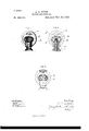
- Figure 1 represents a side elevation of a watch-pendant and its crown and bow, said crown and bow being engaged in accordance with my invention.
- Fig. 2 represents a sectional view of the same.
- Fig. 3 represents a sectional View of a modification.
- a represents a watch-case pendant, and 1) represents the crown attached to the longitudinally-movable winding-bar e.
- Z represents the bow, the ends of which are engaged with the sides of the pendant in the usual or any suitable manner, so that the bow can swing freely from side to side.
- the spring 1' is located between the crown and the end of the pendant, as shownin Fig. 2, the spring being a disk or strip curved to bear at its ends the pendant and the central portion on the hub of the crown, the spring having a central orifice, through which the reduced threaded end of the winding bar 0 passes.
- a stem setting and winding watch the combination, with the pendant and a bow pivoted therein, of a iongitudinally-movable winding and setting bar movable in or out, as the case may be, to wind or set the watch, having a crown with a concavity within which I 5 the end of the pendant fits, said bow and crown bein g formed to engage with each other to hold the crown and winding-stem in, and a disk spring located within the crown and interposed between the same and the end of the pendant for moving the crown and stem outward, substantially as described.
Description
(No Model.)
B. G. FITCH.
WATCH CASE PENDANT.
No. 424,191. Patented Mar. 25, 1890.
UNITED STATES PATENT OFFICE.
EZRA C. FITCH, OF NEWTON, MASSACHUSETTS.
WATCH-CASE PENDANT.
SPECIFICATION forming part of Letters Patent No. 424,191, dated March 25, 1890.
Application filed May 18, 1889. Serial No. 310,525. (No model.)
To all whom it may concern.-
Be it known that LEZRA O. FITCH, of Newton, in the county of Middlesex and State of Massachusetts, have invented certain new and useful Improvements in Safety Devices for Pendant-Setting Watches, of which the following is a specification.
Modern watches of the most approved form are so constructed that the hands can be moved by the pendant-crown, (which is used primarily for the purpose of winding the mainspring,) the engagement of operative parts with the dial-wheels being effected by giving an endwise motion to the winding-bar by pulling the crown outwardly from its winding position. While the extent of this outward motion of the crown is but slight, yet if the said movement or the pull be made easy there is a liability of the hands-setting mechanism being made operative by the watch-wearer in removing the watch from his pocket in case he should grasp the crown in so doing. If the pull be made sufliciently hard to obviate the before-mentioned liability, it may be found diificult for persons having but-little strength in the fingers to pull sufficiently hard to move the crown outwardly, and thereby make the hands-setting mechanism operative.
My invention has for its object to enable the winding-bar and crown to be secured or held by the pendant bow or ring in its windin g or inwardly-thrust position, and prevented thereby from being moved outwardly unless disengaged from the bow, so that the outward pull of the crown may be as easy as may be desired, the liability of accidental outward movement of the crown being prevented by the engagement'of the crown with the how.
To this end the invention consists in certain novel details of construction, to be hereinafter described and claimed.
Of the accompanying drawings, forming a part of this specification, Figure 1 represents a side elevation of a watch-pendant and its crown and bow, said crown and bow being engaged in accordance with my invention. Fig. 2 represents a sectional view of the same. Fig. 3 represents a sectional View of a modification.
The Same letters of reference indicate the same parts in all of the figures.
In the drawings, a represents a watch-case pendant, and 1) represents the crown attached to the longitudinally-movable winding-bar e. (Z represents the bow, the ends of which are engaged with the sides of the pendant in the usual or any suitable manner, so that the bow can swing freely from side to side.
In carrying out my invention I form the how (1 and crown 7) so that they can be interlocked in such manner that the bow will prevent outward movement of the crown. preferred construction whereby this result is produced is that shown in Figs. 1 and 2, in which the bow is shown with an inwardlyprojecting finger or stud e and the crown with a cavity or socket f, formed to receive said stud. It is obvious, however, that the projection can be formed on the crown and the receiving-cavity or socket in the bow, as shown in Fig. The said stud and socket are relatively arranged so that when they are in engagement with each other the crown and winding-bar cannot be moved outwardly to the hands-setting position.
To make the engagement of the crown with the bow sutiiciently fil'11l,I provide a spring'i, whereby the crown may be held with a yielding pressure against the bow, said spring pressing the crown outwardly to a sufficient extent to keep it in engagement with the bow and prevent it from falling away from the how by its own weight when the'pendant is in a vertical position. It is necessary that the crown and how be arranged so that a slight outward movement of the crown will be re quired to engage with the bow, in order that the crown and bow may be disengaged by an inward movement of the crown, said outward movement being, however, insufiicient to make the winding mechanism inoperative and the hands-setting mechanism operative.
The spring 1' is located between the crown and the end of the pendant, as shownin Fig. 2, the spring being a disk or strip curved to bear at its ends the pendant and the central portion on the hub of the crown, the spring having a central orifice, through which the reduced threaded end of the winding bar 0 passes. The advantages of this structure are apparent, in that the invention may be easily applied to watches now in. use without alter- The ing the pendant in the least, and the simplicity of the structure will at once recommend it to manufacturers.
It will be seen that when the bow and crown 5 are engaged outward movement of the crown beyond the point at which it is held by the bow is impossible.
I claim In a stem setting and winding watch, the combination, with the pendant and a bow pivoted therein, of a iongitudinally-movable winding and setting bar movable in or out, as the case may be, to wind or set the watch, having a crown with a concavity within which I 5 the end of the pendant fits, said bow and crown bein g formed to engage with each other to hold the crown and winding-stem in, and a disk spring located within the crown and interposed between the same and the end of the pendant for moving the crown and stem outward, substantially as described.
In testimony whereof I have signed my name to this specification, in the presence of two subscribing witnesses, this 7th day of May, A. D. 1889.
EZRA O. FITCH.
Witnesses:
E. A. MARSH, D. H. CHURCH.
Publications (1)
| Publication Number | Publication Date |
|---|---|
| US424191A true US424191A (en) | 1890-03-25 |
Family
ID=2493105
Family Applications (1)
| Application Number | Title | Priority Date | Filing Date |
|---|---|---|---|
| US424191D Expired - Lifetime US424191A (en) | Watch-case pendant |
Country Status (1)
| Country | Link |
|---|---|
| US (1) | US424191A (en) |
Cited By (2)
| Publication number | Priority date | Publication date | Assignee | Title |
|---|---|---|---|---|
| US2954665A (en) * | 1955-11-30 | 1960-10-04 | Panerai Maria | Tight seal device |
| WO1998043138A1 (en) * | 1997-03-21 | 1998-10-01 | Cartier International B.V. | An improvement in devices for leakproofing instrument-control buttons, particularly for the winding and time-setting buttons of watches |
-
0
- US US424191D patent/US424191A/en not_active Expired - Lifetime
Cited By (3)
| Publication number | Priority date | Publication date | Assignee | Title |
|---|---|---|---|---|
| US2954665A (en) * | 1955-11-30 | 1960-10-04 | Panerai Maria | Tight seal device |
| WO1998043138A1 (en) * | 1997-03-21 | 1998-10-01 | Cartier International B.V. | An improvement in devices for leakproofing instrument-control buttons, particularly for the winding and time-setting buttons of watches |
| US6210034B1 (en) | 1997-03-21 | 2001-04-03 | Cartier International B.V. | Devices for leakproofing instrument-control buttons, particularly for the winding and time-setting buttons of watches |
Similar Documents
| Publication | Publication Date | Title |
|---|---|---|
| US424191A (en) | Watch-case pendant | |
| US1037741A (en) | Balance-cock. | |
| US1085857A (en) | Crown-guard for bracelet-watches. | |
| US163161A (en) | Improvement in mainsprings for watches | |
| US477338A (en) | Watch-case pendant | |
| US243885A (en) | wilhelm gttlzow | |
| US753584A (en) | Watch-mainspring | |
| US420919A (en) | Johann rauschenbacii | |
| US357195A (en) | Watch-case pendant | |
| US441435A (en) | Watch-case pendant | |
| US273759A (en) | Theodore muellee | |
| US137437A (en) | Improvement in mainspring safety attachments for watches | |
| US397504A (en) | Mainspring for watches | |
| US334179A (en) | Iieney a | |
| US112657A (en) | Improvement in attaching the hair-springs of watches | |
| US346254A (en) | abbott | |
| US972520A (en) | Stop-watch. | |
| US347994A (en) | Watch-case pendant | |
| US705703A (en) | Stem-winding watch. | |
| US1206373A (en) | Eight-day alarm-clock. | |
| US437965A (en) | Key for time-pieces | |
| US51414A (en) | Improvement in watch-escapements | |
| US1202292A (en) | Winding mechanism. | |
| US290903A (en) | Stem winding and setting device for watches | |
| US86845A (en) | Improvement in safety-clock keys |