US4228770A - Internal combustion engine fuel supply system - Google Patents
Internal combustion engine fuel supply system Download PDFInfo
- Publication number
- US4228770A US4228770A US06/042,803 US4280379A US4228770A US 4228770 A US4228770 A US 4228770A US 4280379 A US4280379 A US 4280379A US 4228770 A US4228770 A US 4228770A
- Authority
- US
- United States
- Prior art keywords
- passage
- fuel
- region
- cross
- valve
- Prior art date
- Legal status (The legal status is an assumption and is not a legal conclusion. Google has not performed a legal analysis and makes no representation as to the accuracy of the status listed.)
- Expired - Lifetime
Links
Images

Classifications
-
- F—MECHANICAL ENGINEERING; LIGHTING; HEATING; WEAPONS; BLASTING
- F02—COMBUSTION ENGINES; HOT-GAS OR COMBUSTION-PRODUCT ENGINE PLANTS
- F02B—INTERNAL-COMBUSTION PISTON ENGINES; COMBUSTION ENGINES IN GENERAL
- F02B33/00—Engines characterised by provision of pumps for charging or scavenging
- F02B33/02—Engines with reciprocating-piston pumps; Engines with crankcase pumps
- F02B33/04—Engines with reciprocating-piston pumps; Engines with crankcase pumps with simple crankcase pumps, i.e. with the rear face of a non-stepped working piston acting as sole pumping member in co-operation with the crankcase
-
- F—MECHANICAL ENGINEERING; LIGHTING; HEATING; WEAPONS; BLASTING
- F01—MACHINES OR ENGINES IN GENERAL; ENGINE PLANTS IN GENERAL; STEAM ENGINES
- F01L—CYCLICALLY OPERATING VALVES FOR MACHINES OR ENGINES
- F01L3/00—Lift-valve, i.e. cut-off apparatus with closure members having at least a component of their opening and closing motion perpendicular to the closing faces; Parts or accessories thereof
- F01L3/20—Shapes or constructions of valve members, not provided for in preceding subgroups of this group
- F01L3/205—Reed valves
-
- F—MECHANICAL ENGINEERING; LIGHTING; HEATING; WEAPONS; BLASTING
- F02—COMBUSTION ENGINES; HOT-GAS OR COMBUSTION-PRODUCT ENGINE PLANTS
- F02B—INTERNAL-COMBUSTION PISTON ENGINES; COMBUSTION ENGINES IN GENERAL
- F02B33/00—Engines characterised by provision of pumps for charging or scavenging
- F02B33/02—Engines with reciprocating-piston pumps; Engines with crankcase pumps
- F02B33/28—Component parts, details or accessories of crankcase pumps, not provided for in, or of interest apart from, subgroups F02B33/02 - F02B33/26
- F02B33/30—Control of inlet or outlet ports
-
- F—MECHANICAL ENGINEERING; LIGHTING; HEATING; WEAPONS; BLASTING
- F16—ENGINEERING ELEMENTS AND UNITS; GENERAL MEASURES FOR PRODUCING AND MAINTAINING EFFECTIVE FUNCTIONING OF MACHINES OR INSTALLATIONS; THERMAL INSULATION IN GENERAL
- F16K—VALVES; TAPS; COCKS; ACTUATING-FLOATS; DEVICES FOR VENTING OR AERATING
- F16K15/00—Check valves
- F16K15/14—Check valves with flexible valve members
- F16K15/1401—Check valves with flexible valve members having a plurality of independent valve members
-
- F—MECHANICAL ENGINEERING; LIGHTING; HEATING; WEAPONS; BLASTING
- F16—ENGINEERING ELEMENTS AND UNITS; GENERAL MEASURES FOR PRODUCING AND MAINTAINING EFFECTIVE FUNCTIONING OF MACHINES OR INSTALLATIONS; THERMAL INSULATION IN GENERAL
- F16K—VALVES; TAPS; COCKS; ACTUATING-FLOATS; DEVICES FOR VENTING OR AERATING
- F16K15/00—Check valves
- F16K15/14—Check valves with flexible valve members
- F16K15/16—Check valves with flexible valve members with tongue-shaped laminae
-
- F—MECHANICAL ENGINEERING; LIGHTING; HEATING; WEAPONS; BLASTING
- F02—COMBUSTION ENGINES; HOT-GAS OR COMBUSTION-PRODUCT ENGINE PLANTS
- F02B—INTERNAL-COMBUSTION PISTON ENGINES; COMBUSTION ENGINES IN GENERAL
- F02B75/00—Other engines
- F02B75/02—Engines characterised by their cycles, e.g. six-stroke
- F02B2075/022—Engines characterised by their cycles, e.g. six-stroke having less than six strokes per cycle
- F02B2075/025—Engines characterised by their cycles, e.g. six-stroke having less than six strokes per cycle two
-
- Y—GENERAL TAGGING OF NEW TECHNOLOGICAL DEVELOPMENTS; GENERAL TAGGING OF CROSS-SECTIONAL TECHNOLOGIES SPANNING OVER SEVERAL SECTIONS OF THE IPC; TECHNICAL SUBJECTS COVERED BY FORMER USPC CROSS-REFERENCE ART COLLECTIONS [XRACs] AND DIGESTS
- Y10—TECHNICAL SUBJECTS COVERED BY FORMER USPC
- Y10T—TECHNICAL SUBJECTS COVERED BY FORMER US CLASSIFICATION
- Y10T137/00—Fluid handling
- Y10T137/7722—Line condition change responsive valves
- Y10T137/7837—Direct response valves [i.e., check valve type]
- Y10T137/7838—Plural
- Y10T137/7839—Dividing and recombining in a single flow path
-
- Y—GENERAL TAGGING OF NEW TECHNOLOGICAL DEVELOPMENTS; GENERAL TAGGING OF CROSS-SECTIONAL TECHNOLOGIES SPANNING OVER SEVERAL SECTIONS OF THE IPC; TECHNICAL SUBJECTS COVERED BY FORMER USPC CROSS-REFERENCE ART COLLECTIONS [XRACs] AND DIGESTS
- Y10—TECHNICAL SUBJECTS COVERED BY FORMER USPC
- Y10T—TECHNICAL SUBJECTS COVERED BY FORMER US CLASSIFICATION
- Y10T137/00—Fluid handling
- Y10T137/7722—Line condition change responsive valves
- Y10T137/7837—Direct response valves [i.e., check valve type]
- Y10T137/7879—Resilient material valve
- Y10T137/7888—With valve member flexing about securement
- Y10T137/7891—Flap or reed
Definitions
- This invention relates to internal combustion engines and is particularly concerned with a fuel supply system arranged to provide increased efficiency in the delivery of fuel to the engine.
- the invention is applicable to engines of various kinds having a combustion chamber and having fuel inlet porting for delivering fuel either directly or indirectly to the combustion chamber, and certain aspects of the invention are applicable to engines of a variety of types, including engines with cylinders and reciprocating pistons therein, and engines in which the combustion chamber accommodates a rotary type of piston.
- the invention is applicable to a broad range of reciprocating piston and cylinder types of engines, the invention is herein illustrated and described as applied to a two-cycle internal combustion engine of the kind commonly employed in motorcycles, power saws, lawn mowers and other appliances and devices.
- the invention may be employed in association with fuel intake and valving systems of various kinds, the invention is particularly applicable in engines in which reed valves are employed in the fuel intake system, and the invention is, therefore, herein illustrated and described in connection with two-cycle engines employing reed valves.
- fuel intake porting is provided and the fuel supply means includes passage walls defining a fuel passage communicating with the inlet porting and having valve means in the passage to control the flow of fuel in the passage.
- the portion of the fuel supply passage extending upstream to the carburetor or other means for introducing the fuel into the system commonly has a cross-sectional area considerably smaller than the cross-sectional area in the region of the reed valves. It is of advantage in connection with the operation of the carburetor to avoid having a fuel delivery passage of excessive cross-sectional area, because for a given quantity of fuel and air, the rate of flow would be retarded; and in the operation of carburetors generally, the quantity of air and fuel intermixed in the carburetor is more accurately and reliably established where the velocity of delivery of the mixture is relatively high. It is, therefore, of significance in the operation of the carburetor to employ a delivery passage of relatively small cross-sectional area.
- the present invention contemplates the provision of a means tending to equalize the fuel flow velocity in the supply passage, especially in the region of the valves where the passage walls ordinarily define a relatively large cross-sectional area.
- the foregoing objective is achieved by the positioning of a bar-shaped element within the supply passage just upstream of the valves, the bar-shaped element preferably being of airfoil or aerodynamic shape having a rounded leading edge presented upstream in the flow passage and having an angular trailing edge portion presented downstream.
- the cross-sectional area of said element in a plane transverse to the fuel supply passage be sufficient to substantially reduce the effective cross-sectional flow area in the region in which the passage walls would otherwise provide a relatively large cross-sectional flow area. In this way, the velocity of the fuel flow may be substantially maintained, with resultant improvement in efficiency and operating characteristics of the engine.
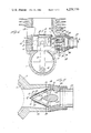
- FIG. 1 is a vertical sectional view through portions of a two-cycle internal combustion engine, in which the fuel supply system includes a plurality of reed valves arranged in association with a reed valve support or "cage" having its apex presented downstream of the fuel supply passage and in a position extended generally parallel to the axis of the cylinder;
- FIG. 2 is a fragmentary horizontal sectional view taken as indicated by the section line 2--2 on FIG. 1, FIG. 2 being on an enlarged scale, as compared with FIG. 1;
- FIG. 3 is a fragmentary view similar to FIG. 1 but illustrating another embodiment of the invention, in which the features of the invention are applied to a two-cycle internal combustion engine having a reed cage positioned with its axis extended generally transverse to the axis of the cylinder; and
- FIG. 4 is a horizontal sectional view taken as indicated by the section line 4--4 on FIG. 3, FIG. 4 being on a enlarged scale, as compared with FIG. 3.
- a cylinder is indicated at 5, the cylinder having a liner 6 and being associated with a crankcase 7.
- the top closure of the cylinder is not illustrated.
- the piston 8 reciprocates in the cylinder and is associated with a connecting rod 9 associated with the crank 10 in the crankcase.
- the crank 10 rotates about the crankshaft (not shown), which may also carry the counterweight 11, all as is well-known in this art.
- An intake port is indicated at 12, and the cylinder also has an exhaust port 13 and a transfer port 14 which communicates with the space below the piston by means of a transfer passage 15 formed in the wall of the cylinder.
- the fuel and air mixture is admitted into the space below the piston when the piston is in its upper position, and as the piston moves downwardly toward bottom dead center position (the position shown in FIG. 1), the fuel is compressed in the space below the piston, so that at the bottom dead center position, when the transfer port 14 has been opened, the compressed fuel will flow upwardly through the transfer passage 15 and into the cylinder through the transfer port 14.
- a reed valve cage of generally triangular cross section 16 is illustrated, this cage being formed of two valve seats positioned in planes which converge toward each other, i.e., toward the apex member 17, each of the valve seats 16 being provided with a series of valve ports 18 (four such ports being included in this embodiment) through which the fuel passes into the inlet port or porting 12, and thence either directly or indirectly into the combustion space in the cylinder for ultimate combustion to produce the downstroke of the piston.
- a flange 19 is provided which is adapted to be mounted against the extension 20 projecting from the cylinder in order to accommodate and mount the valve means in the fluid flow passage delivering fuel to the intake porting 12.
- each of the valve seats 16 reed valves are provided; and in the embodiment here illustrated, the reed valves associated with each port 18 include a primary reed 21 and a secondary reed 22.
- the reeds are secured in position by means of screws 23.
- each primary reed 21 is of sufficient size to overlie the entire area of the valve port 18 in the seat, and each such primary reed has a "vent" therein as indicated at 24, which vent is adapted to be covered by the secondary reed 22.
- the inlet porting 12 is of substantial dimension axially of the cylinder and is open to the space below the piston even when the piston is in bottom dead center position.
- a passage 25 extends upwardly from the porting 12 and communicates with the space above the piston in bottom dead center position through a port indicated at 26, such passage and port providing for supplemental transfer and fuel intake when the piston is in the bottom dead center position.
- the duct or connection 27, which is associated with the carburetor (not shown), is ordinarily of circular cross section; and as above indicated, is of substantially smaller internal cross-sectional area than the chamber within the extension 20 of the cylinder which accommodates the valve mechanism.
- a connecting part 28 Intervening between the duct 27 and the upstream edge of the reed valve cage, there is a connecting part 28 having diverging interior walls 29, this connecting part conveniently being formed of rubber or some composition material and adapted to be fastened at its downstream end to the cylinder through the reed cage flange 19 and adapted to be connected with the duct 27 in any suitable manner.
- the passage walls leading from the carburetor to the intake porting have an internal cross-sectional area which is relatively large in a region at the upstream side of the valve means, as compared with the region in the duct 27 leading to the carburetor; and in the absence of provision to the contrary, this variation in the cross-sectional area of the flow passage would result in substantial decrease in velocity of the fuel mixture in a region just upstream of the valves.
- the present invention contemplates the provision of means tending to equalize the velocity of the fuel flow through the various regions of the intake passage.
- the objective is achieved by the employment of an element 30 positioned within the region upstream of the valves where the cross-sectional area within the passage walls is relatively large, as compared with the upstream region extended to the carburetor.
- the element 30 preferably takes the form of a bar with its axis extended parallel to the planes of the valve seats 16 and parallel also to the apex member 17 of the reed cage.
- the bar may desirably be formed integrally with the end walls 31 of the reed cage itself although a portion of the bar projects upstream from the reed cage.
- the element 30 has an aerodynamic or airfoil contour with a rounded leading edge presented upstream and with an angled training edge presented downstream.
- the cross-sectional area of the bar 30 is advantageously sufficient to approximately equalize the effective cross-sectional area of flow passage in the region of the bar as compared with the region upstream in the duct 27 extended to the carburetor.
- the trailing edge surfaces in the downstream portion of the bar 30 should substantially parallel the valve seat walls 16. This aerodynamic shape effectively serves to minimize fluctuation in the velocity of the fuel flow, without substantial impedence of the flow. As seen in FIG.
- the apex member 17 of the reed cage also desirably has an aerodynamic cross-sectional shape, with the rounded leading edge presented upstream toward the trailing edge of the bar 30, and this further enhances the aerodynamic action in maximizing the flow of the fuel through the valve ports 18.
- the secondary reed In the absence of the aerodynamic bar, the secondary reed would be located in a region of lower fuel flow velocity; but with the presence of the aerodynamic bar, the opening of the secondary reeds is accelerated because of the increase in the fuel flow velocity in the region of the tip of each secondary reed.
- the intake porting 12 extends downwardly sufficiently to provide for communication with the space below the piston above the crankcase space, even when the piston is in bottom dead center position, and this provision, together with the supplemental port 25, is effective in maximizing fuel delivery into the combustion chamber above the piston.
- the space below the piston also communicates with the crankcase space.
- FIGS. 3 and 4 some of the parts are identified by the same reference characters as used in FIGS. 1 and 2, and the general arrangement of the cylinder, piston and crankcase will be apparent without repetitive description.
- a supplemental intake or transfer passage 25 is provided, but the intake porting 12 does not extend downwardly in the cylinder wall to a point below the piston. Instead of such opening, a port 32 is provided in the skirt of the piston, this port being positioned so that it will serve to extend the effective intake porting to provide for fuel intake throughout the entire stroke of the piston, as is the case in FIGS. 1 and 2, by virtue of the downward extension of the intake porting itself to the region below the piston skirt.
- the reed cage and reed valves comprise essentially the same components as described above with reference to FIGS. 1 and 2; but in FIGS. 3 and 4, the reed cage is positioned with its apex 17 extended transverse to the cylinder axis, instead of in a direction parallelling the cylinder axis, as in FIGS. 1 and 2.
- the reed cage is mounted by means of its base flange 19 on the outer edge of the extension 20a of the cylinder 5.
- the inside walls 29a of the connecting part 28a are, of course, extended in divergent planes which are somewhat differently arranged than in FIGS. 1 and 2, because of the different orientation of the parts.
- the aerodynamic bar 30a employed in the embodiment of FIGS. 3 and 4 is also somewhat differently shaped as may readily be seen in order to span the space between the inclined walls 29a in the connecting part 28a.
- the bar 30a is shown as being formed as a separate part from the reed cage, but is secured in the reed cage by means of screws 33, which are extended through the end walls 31 of the reed cage.
- the aerodynamic shape, positioning and proportioning of the element 30a in the arrangement of FIGS. 3 and 4, may be as described above in connection with the element 30 of FIGS. 1 and 2.
- the proportioning and positioning of the aerodynamic bar employed to equalize the fuel velocity in different portions of the intake tract may be varied according to the shape of the passages involved.
- somewhat different cross-sectional shapes may be employed for the element introduced in the fuel flow passage, but an aerodynamic cross-sectional shape is preferred because it is effective for the purpose of equalizing the velocity while at the same time, minimizing aerodynamic drag which would unnecessarily impede the flow of the fuel.
- Dynamometer testing of an arrangement as herein disclosed established that the arrangement of the invention not only improved the fuel intake and carburetor function at the low and mid-range of engine speeds, but also effected increase in power and decrease in fuel consumption at the high end of the speed range.
Landscapes
- Engineering & Computer Science (AREA)
- General Engineering & Computer Science (AREA)
- Mechanical Engineering (AREA)
- Chemical & Material Sciences (AREA)
- Combustion & Propulsion (AREA)
- Physics & Mathematics (AREA)
- Geometry (AREA)
- Check Valves (AREA)
- Supercharger (AREA)
Priority Applications (3)
| Application Number | Priority Date | Filing Date | Title |
|---|---|---|---|
| US06/042,803 US4228770A (en) | 1979-05-29 | 1979-05-29 | Internal combustion engine fuel supply system |
| CA352,247A CA1134223A (en) | 1979-05-29 | 1980-05-20 | Internal combustion engine fuel supply system |
| JP7021580A JPS55164766A (en) | 1979-05-29 | 1980-05-28 | Fuel feed system for internal combustion engine |
Applications Claiming Priority (1)
| Application Number | Priority Date | Filing Date | Title |
|---|---|---|---|
| US06/042,803 US4228770A (en) | 1979-05-29 | 1979-05-29 | Internal combustion engine fuel supply system |
Publications (1)
| Publication Number | Publication Date |
|---|---|
| US4228770A true US4228770A (en) | 1980-10-21 |
Family
ID=21923835
Family Applications (1)
| Application Number | Title | Priority Date | Filing Date |
|---|---|---|---|
| US06/042,803 Expired - Lifetime US4228770A (en) | 1979-05-29 | 1979-05-29 | Internal combustion engine fuel supply system |
Country Status (3)
| Country | Link |
|---|---|
| US (1) | US4228770A (ja) |
| JP (1) | JPS55164766A (ja) |
| CA (1) | CA1134223A (ja) |
Cited By (33)
| Publication number | Priority date | Publication date | Assignee | Title |
|---|---|---|---|---|
| JPS5779220A (en) * | 1980-11-05 | 1982-05-18 | Yamaha Motor Co Ltd | Two cycle engine |
| US4333425A (en) * | 1980-12-29 | 1982-06-08 | Brunswick Corporation | Fuel system for a two-cycle engine |
| FR2519076A1 (fr) * | 1981-12-28 | 1983-07-01 | Brunswick Corp | Systeme d'admission pour un moteur a deux temps a combustion interne |
| US4395978A (en) * | 1980-03-24 | 1983-08-02 | Performance Industries, Inc. | Fuel porting for two-cycle internal combustion engine |
| US4449242A (en) * | 1982-08-31 | 1984-05-15 | The United States Of America As Represented By The Secretary Of The Air Force | Flexible, resilient anti-contamination baffle |
| US4474145A (en) * | 1983-08-10 | 1984-10-02 | Performance Industries, Inc. | Fuel supply system for internal combustion engine |
| US4475487A (en) * | 1981-12-04 | 1984-10-09 | Kioritz Corporation | Joint-pipe for carburetor |
| US4542768A (en) * | 1984-03-12 | 1985-09-24 | Rotron, Inc. | Pressure relief valve |
| WO1986001859A1 (en) * | 1984-09-21 | 1986-03-27 | Lowi Alvin Jr | Supplemental fueling of compression ignition engines |
| US4643139A (en) * | 1983-07-20 | 1987-02-17 | Hargreaves Bernard J | Reed valves for internal combustion engines |
| US4696263A (en) * | 1985-07-12 | 1987-09-29 | Performance Industries, Inc. | Reed valves for internal combustion engines |
| EP0268339A2 (en) * | 1986-11-17 | 1988-05-25 | ADLER S.p.A. | Non-return reed valve for the delivery of fuel into internal combustion engines, with directed flow and maximum adjustable opening, with elastic resistance plates |
| EP0312255A2 (en) * | 1987-10-12 | 1989-04-19 | Suzuki Jidosha Kogyo Kabushiki Kaisha | V-type multiple cylinder two-cycle engine |
| US4836151A (en) * | 1988-03-31 | 1989-06-06 | Brunswick Corporation | Two cycle engine with turbulence generator at reed valves |
| US4858594A (en) * | 1988-03-28 | 1989-08-22 | K-S-H Canada Inc. | Solar heating panel with curvilinear passageway |
| US4879976A (en) * | 1987-09-09 | 1989-11-14 | Performance Industries, Inc. | Reed valve mechanism for engines |
| US4905638A (en) * | 1989-03-10 | 1990-03-06 | Brunswick Corporation | Two stage carburetor |
| EP0426223A1 (en) * | 1989-10-31 | 1991-05-08 | ADLER S.p.A. | Non-return valve of the flap type for flow concentration |
| US5065708A (en) * | 1989-11-03 | 1991-11-19 | Andreas Stihl | Internal combustion engine for a portable handheld work apparatus |
| US5097814A (en) * | 1990-09-17 | 1992-03-24 | Smith George C | Tuned air insert for internal combustion engines and related process |
| US5143027A (en) * | 1991-05-01 | 1992-09-01 | Land & Sea, Inc. | Reed valves for two stroke engines |
| US5245956A (en) * | 1993-01-11 | 1993-09-21 | Barry Davidson | Reed valve assembly |
| US5370088A (en) * | 1992-11-16 | 1994-12-06 | Sanshin Kogyo Kabushiki Kaisha | Two cycle engine |
| US5447129A (en) * | 1993-11-16 | 1995-09-05 | Kioritz Corporation | Intake insulator |
| US5636658A (en) * | 1995-01-24 | 1997-06-10 | Powell; William F. | High flow reed valve |
| US5992451A (en) * | 1998-03-09 | 1999-11-30 | Chang; Paul C. | Reed valve for pool cleaner |
| US20060102114A1 (en) * | 2004-11-01 | 2006-05-18 | Brad Holtorf | Motorcycle engine method & apparatus |
| US20100038805A1 (en) * | 2008-08-13 | 2010-02-18 | 3W-Modellmotoren Gmbh | Two-stroke engine and method for operating a two-stroke engine |
| US20110204162A1 (en) * | 2005-05-18 | 2011-08-25 | United Technologies Corporation | Arrangement for controlling fluid jets injected into a fluid stream |
| US8118574B1 (en) | 2008-10-03 | 2012-02-21 | Aci Services, Inc. | Radial suction valve assembly for a compressor |
| US20150159591A1 (en) * | 2012-07-04 | 2015-06-11 | Pierburg Gmbh | Non-return valve device for an internal combustion engine |
| US11378195B2 (en) * | 2020-04-06 | 2022-07-05 | Mikuni Corporation | Reed valve |
| US11454162B2 (en) * | 2020-03-12 | 2022-09-27 | Moto Tassinari, Inc. | Reed valve and reed valve airbox |
Citations (6)
| Publication number | Priority date | Publication date | Assignee | Title |
|---|---|---|---|---|
| US2332916A (en) * | 1942-08-26 | 1943-10-26 | Gen Electric | Internal combustion engine arrangement |
| US2442217A (en) * | 1945-08-13 | 1948-05-25 | Chris Craft Corp | Two-cycle crankcase compression engine, fuel distribution control |
| US2459594A (en) * | 1946-01-02 | 1949-01-18 | Chris Craft Corp | Manifold for two-cycle crankcase compression engines |
| US2639699A (en) * | 1951-09-01 | 1953-05-26 | Elmer C Kiekhaefer | Two-cycle engine and improved crankcase induction means therefor |
| US3008459A (en) * | 1960-05-25 | 1961-11-14 | Jacobsen Mfg Co | Fuel induction system for gasoline engine |
| US3905340A (en) * | 1972-08-22 | 1975-09-16 | Performance Industries | Engine valving and porting |
-
1979
- 1979-05-29 US US06/042,803 patent/US4228770A/en not_active Expired - Lifetime
-
1980
- 1980-05-20 CA CA352,247A patent/CA1134223A/en not_active Expired
- 1980-05-28 JP JP7021580A patent/JPS55164766A/ja active Granted
Patent Citations (6)
| Publication number | Priority date | Publication date | Assignee | Title |
|---|---|---|---|---|
| US2332916A (en) * | 1942-08-26 | 1943-10-26 | Gen Electric | Internal combustion engine arrangement |
| US2442217A (en) * | 1945-08-13 | 1948-05-25 | Chris Craft Corp | Two-cycle crankcase compression engine, fuel distribution control |
| US2459594A (en) * | 1946-01-02 | 1949-01-18 | Chris Craft Corp | Manifold for two-cycle crankcase compression engines |
| US2639699A (en) * | 1951-09-01 | 1953-05-26 | Elmer C Kiekhaefer | Two-cycle engine and improved crankcase induction means therefor |
| US3008459A (en) * | 1960-05-25 | 1961-11-14 | Jacobsen Mfg Co | Fuel induction system for gasoline engine |
| US3905340A (en) * | 1972-08-22 | 1975-09-16 | Performance Industries | Engine valving and porting |
Cited By (43)
| Publication number | Priority date | Publication date | Assignee | Title |
|---|---|---|---|---|
| US4395978A (en) * | 1980-03-24 | 1983-08-02 | Performance Industries, Inc. | Fuel porting for two-cycle internal combustion engine |
| JPS5779220A (en) * | 1980-11-05 | 1982-05-18 | Yamaha Motor Co Ltd | Two cycle engine |
| US4333425A (en) * | 1980-12-29 | 1982-06-08 | Brunswick Corporation | Fuel system for a two-cycle engine |
| US4475487A (en) * | 1981-12-04 | 1984-10-09 | Kioritz Corporation | Joint-pipe for carburetor |
| FR2519076A1 (fr) * | 1981-12-28 | 1983-07-01 | Brunswick Corp | Systeme d'admission pour un moteur a deux temps a combustion interne |
| DE3248361A1 (de) * | 1981-12-28 | 1983-07-28 | Brunswick Corp., 60077 Skokie, Ill. | Einlassanordnung fuer einen zweitaktmotor |
| US4449242A (en) * | 1982-08-31 | 1984-05-15 | The United States Of America As Represented By The Secretary Of The Air Force | Flexible, resilient anti-contamination baffle |
| US4643139A (en) * | 1983-07-20 | 1987-02-17 | Hargreaves Bernard J | Reed valves for internal combustion engines |
| US4474145A (en) * | 1983-08-10 | 1984-10-02 | Performance Industries, Inc. | Fuel supply system for internal combustion engine |
| US4542768A (en) * | 1984-03-12 | 1985-09-24 | Rotron, Inc. | Pressure relief valve |
| WO1986001859A1 (en) * | 1984-09-21 | 1986-03-27 | Lowi Alvin Jr | Supplemental fueling of compression ignition engines |
| US4694802A (en) * | 1984-09-21 | 1987-09-22 | Lowi Jr Alvin | Compression ignition engine fumigation system |
| AU584928B2 (en) * | 1984-09-21 | 1989-06-08 | Alvin Lowi Jr. | Supplemental fueling of compression ignition engines |
| US4696263A (en) * | 1985-07-12 | 1987-09-29 | Performance Industries, Inc. | Reed valves for internal combustion engines |
| EP0268339A2 (en) * | 1986-11-17 | 1988-05-25 | ADLER S.p.A. | Non-return reed valve for the delivery of fuel into internal combustion engines, with directed flow and maximum adjustable opening, with elastic resistance plates |
| EP0268339A3 (en) * | 1986-11-17 | 1989-08-09 | ADLER S.p.A. | Non-return reed valve for the delivery of fuel into internal combustion engines, with directed flow and maximum adjustable opening, with elastic resistance plates |
| US4879976A (en) * | 1987-09-09 | 1989-11-14 | Performance Industries, Inc. | Reed valve mechanism for engines |
| EP0312255A3 (en) * | 1987-10-12 | 1989-10-25 | Suzuki Jidosha Kogyo Kabushiki Kaisha | V-type multiple cylinder two-cycle engine |
| EP0312255A2 (en) * | 1987-10-12 | 1989-04-19 | Suzuki Jidosha Kogyo Kabushiki Kaisha | V-type multiple cylinder two-cycle engine |
| US4858594A (en) * | 1988-03-28 | 1989-08-22 | K-S-H Canada Inc. | Solar heating panel with curvilinear passageway |
| US4836151A (en) * | 1988-03-31 | 1989-06-06 | Brunswick Corporation | Two cycle engine with turbulence generator at reed valves |
| US4905638A (en) * | 1989-03-10 | 1990-03-06 | Brunswick Corporation | Two stage carburetor |
| EP0426223A1 (en) * | 1989-10-31 | 1991-05-08 | ADLER S.p.A. | Non-return valve of the flap type for flow concentration |
| US5027754A (en) * | 1989-10-31 | 1991-07-02 | Adler S.P.A. | Non-return valve of the flap type for flow concentration |
| US5065708A (en) * | 1989-11-03 | 1991-11-19 | Andreas Stihl | Internal combustion engine for a portable handheld work apparatus |
| US5097814A (en) * | 1990-09-17 | 1992-03-24 | Smith George C | Tuned air insert for internal combustion engines and related process |
| US5143027A (en) * | 1991-05-01 | 1992-09-01 | Land & Sea, Inc. | Reed valves for two stroke engines |
| US5370088A (en) * | 1992-11-16 | 1994-12-06 | Sanshin Kogyo Kabushiki Kaisha | Two cycle engine |
| US5245956A (en) * | 1993-01-11 | 1993-09-21 | Barry Davidson | Reed valve assembly |
| US5447129A (en) * | 1993-11-16 | 1995-09-05 | Kioritz Corporation | Intake insulator |
| US5636658A (en) * | 1995-01-24 | 1997-06-10 | Powell; William F. | High flow reed valve |
| US5992451A (en) * | 1998-03-09 | 1999-11-30 | Chang; Paul C. | Reed valve for pool cleaner |
| US20060102114A1 (en) * | 2004-11-01 | 2006-05-18 | Brad Holtorf | Motorcycle engine method & apparatus |
| US7458344B2 (en) * | 2004-11-01 | 2008-12-02 | Brad Holtorf | Motorcycle engine method and apparatus |
| US8683812B2 (en) * | 2005-05-18 | 2014-04-01 | United Technologies Corporation | Arrangement for controlling fluid jets injected into a fluid stream of a bleed air discharge nozzle |
| US20110204162A1 (en) * | 2005-05-18 | 2011-08-25 | United Technologies Corporation | Arrangement for controlling fluid jets injected into a fluid stream |
| US8038130B2 (en) * | 2008-08-13 | 2011-10-18 | 3W-Modellmotoren Gmbh | Two-stroke engine and method for operating a two-stroke engine |
| US20100038805A1 (en) * | 2008-08-13 | 2010-02-18 | 3W-Modellmotoren Gmbh | Two-stroke engine and method for operating a two-stroke engine |
| US8118574B1 (en) | 2008-10-03 | 2012-02-21 | Aci Services, Inc. | Radial suction valve assembly for a compressor |
| US20150159591A1 (en) * | 2012-07-04 | 2015-06-11 | Pierburg Gmbh | Non-return valve device for an internal combustion engine |
| US9624878B2 (en) * | 2012-07-04 | 2017-04-18 | Pierburg Gmbh | Non-return valve device for an internal combustion engine |
| US11454162B2 (en) * | 2020-03-12 | 2022-09-27 | Moto Tassinari, Inc. | Reed valve and reed valve airbox |
| US11378195B2 (en) * | 2020-04-06 | 2022-07-05 | Mikuni Corporation | Reed valve |
Also Published As
| Publication number | Publication date |
|---|---|
| CA1134223A (en) | 1982-10-26 |
| JPS55164766A (en) | 1980-12-22 |
| JPS6122127B2 (ja) | 1986-05-30 |
Similar Documents
| Publication | Publication Date | Title |
|---|---|---|
| US4228770A (en) | Internal combustion engine fuel supply system | |
| US4774919A (en) | Combustion chamber importing system for two-cycle diesel engine | |
| US3905340A (en) | Engine valving and porting | |
| US2459594A (en) | Manifold for two-cycle crankcase compression engines | |
| US4228772A (en) | Low throttled volume engine | |
| US4161163A (en) | Two cycle internal combustion engine | |
| US4000723A (en) | Engine valve means and porting | |
| US4051820A (en) | Engine valving and porting | |
| JPH01253526A (ja) | 可変面積式吸入系統を含む内燃機関 | |
| US2782777A (en) | Internal combustion engines | |
| US5487365A (en) | Induction system for engine | |
| US4235206A (en) | Two cycle internal combustion engine | |
| US5345897A (en) | Gas-exchanging process for two-stroke, internal combustion engines | |
| US4318380A (en) | Intake system for multi-cylinder internal combustion engine | |
| US2698613A (en) | Fuel-air mixture induction system for internal-combustion engines | |
| US4294202A (en) | Fuel porting for two cycle internal combustion engine | |
| US4389982A (en) | Internal combustion engine fuel supply system | |
| US4180042A (en) | Fuel-air mixture regulator for internal combustion engines | |
| US4004557A (en) | Piston-cylinder assembly | |
| US4408579A (en) | Induction system for a two-cycle engine | |
| US4181101A (en) | Two-cycle internal combustion engines with scavenger means | |
| US5829394A (en) | Exhaust controller for spark ignition type two stroke internal combustion engine | |
| US4202299A (en) | Two cycle internal combustion engine | |
| US5549088A (en) | Induction system for engine | |
| US20030217712A1 (en) | Port-controlled two-cycle engine having scavenging |