US422250A - pullin - Google Patents
pullin Download PDFInfo
- Publication number
- US422250A US422250A US422250DA US422250A US 422250 A US422250 A US 422250A US 422250D A US422250D A US 422250DA US 422250 A US422250 A US 422250A
- Authority
- US
- United States
- Prior art keywords
- plate
- nut
- clasps
- bolt
- projections
- Prior art date
- Legal status (The legal status is an assumption and is not a legal conclusion. Google has not performed a legal analysis and makes no representation as to the accuracy of the status listed.)
- Expired - Lifetime
Links
- 238000010168 coupling process Methods 0.000 description 3
- 238000005859 coupling reaction Methods 0.000 description 3
- 238000007373 indentation Methods 0.000 description 3
- 230000008878 coupling Effects 0.000 description 2
- 230000000694 effects Effects 0.000 description 2
- 238000010276 construction Methods 0.000 description 1
- 230000008602 contraction Effects 0.000 description 1
- 238000003780 insertion Methods 0.000 description 1
- 230000037431 insertion Effects 0.000 description 1
- 239000002023 wood Substances 0.000 description 1
Images
Classifications
-
- F—MECHANICAL ENGINEERING; LIGHTING; HEATING; WEAPONS; BLASTING
- F16—ENGINEERING ELEMENTS AND UNITS; GENERAL MEASURES FOR PRODUCING AND MAINTAINING EFFECTIVE FUNCTIONING OF MACHINES OR INSTALLATIONS; THERMAL INSULATION IN GENERAL
- F16B—DEVICES FOR FASTENING OR SECURING CONSTRUCTIONAL ELEMENTS OR MACHINE PARTS TOGETHER, e.g. NAILS, BOLTS, CIRCLIPS, CLAMPS, CLIPS OR WEDGES; JOINTS OR JOINTING
- F16B39/00—Locking of screws, bolts or nuts
- F16B39/22—Locking of screws, bolts or nuts in which the locking takes place during screwing down or tightening
- F16B39/24—Locking of screws, bolts or nuts in which the locking takes place during screwing down or tightening by means of washers, spring washers, or resilient plates that lock against the object
-
- Y—GENERAL TAGGING OF NEW TECHNOLOGICAL DEVELOPMENTS; GENERAL TAGGING OF CROSS-SECTIONAL TECHNOLOGIES SPANNING OVER SEVERAL SECTIONS OF THE IPC; TECHNICAL SUBJECTS COVERED BY FORMER USPC CROSS-REFERENCE ART COLLECTIONS [XRACs] AND DIGESTS
- Y10—TECHNICAL SUBJECTS COVERED BY FORMER USPC
- Y10S—TECHNICAL SUBJECTS COVERED BY FORMER USPC CROSS-REFERENCE ART COLLECTIONS [XRACs] AND DIGESTS
- Y10S411/00—Expanded, threaded, driven, headed, tool-deformed, or locked-threaded fastener
- Y10S411/924—Coupled nut and bolt
- Y10S411/943—Flexible washer
Definitions
- This invention relates to a nut-lock; and the invention consists in the combination of certain bolts, sliding latch-plates, or plates with clasps, and suitable nuts, and other combinations for making permanent or temporary but secure joints or fastenings, all of which will be hereinafter more particularly set forth and then claimed.
- clasp-provided plate is adapted to fit.
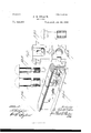
- Figure 1 is a perspective view of the contiguous ends of two rails which are coupled together by means of my improved railway-rail-joint fastening.
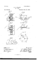
- Fig. 2 is a perspective view of the sliding latchplate having clasps adapted to be turned or bent into corresponding notches or concavities in a suitable nut, which is to be screwed against it when upon the bolt, and having a centrallydocated hole or perforation through which the bolt is to pass, that portion of the sliding latch occupied by the hole being wedged or beveled from above downward and from the fore backward, so that when it is passed over the threaded end of the bolt it can be wedged down into the neck of the same.
- FIG. 3 is a perspective view of one of the nuts employed in my invention, said nut having four notches or indentations, one on each side, which are adapted for the reception of the clasps on the sliding washers or plates.
- Fig. 4 is a view of one form of bolt employed in this invention, which is slightly flattened throughout its length on two opposite sides and is formed with a square or rounded neck locatedat the inner end of its threaded portion, into which neck the sliding latch or
- Fig. 5 is aview showing another form of bolt, which is rounded throughout and provided with a square neck.
- Fig. 6 isaview of another form of bolthaving a longer neck than that form shown in Figs. 4 and 5, so as to give more freedom for extensive expansion and contraction.
- Fig. 4 is a view of one form of bolt employed in this invention, which is slightly flattened throughout its length on two opposite sides and is formed with a square or rounded neck locatedat the inner end of its threaded portion, into which neck the sliding latch or
- FIG. 7 is a cross-section of a rail, the fish-plate, and the parts of my improvement.
- Fig. 8 is a longitudinal section of the same.
- Fig. 9 is a front view of one of the sliding latch-plates similar to that shown in Fig. 2, but provided with clasps fitted with springs and hinges, which operate upon the clasps in a manner similar to that of the spring of a peneknife upon its blade, so that the clasp may be locked or unlocked when desired.
- Fig. 10 is a cross-section-on line was of Fig. 9.
- Fig. 11 is a View of aplate, which may be of any shape or may have any number of holes and projections, said plate being used for splicings in connecting girders or other joints.
- Fig. 12 is a plan View of a circular plate with spring or plain clasps for securely fastening ends of cylinders, 820.
- Fig. 1 a portion of a tram or rail way line in connection with which my improved railway-rail-joint fastening or coup ling is arranged.
- AA denote the contiguous ends of two railway-rails
- B B represent the fish-plates located on the opposite sides of the rails, said fish-plates being provided with any suitable number ,of apertures or holes;
- the slidinglatchplate D (see Fig. 2) is then located upon the projecting end of the bolt 0 by passing it over the threaded end thereof and causing it to slide down and fit nicely within the neck a.
- This latch-plate will fit nicely between the fish-plate and the collar formed on the inner end of the threaded portion of the bolt, thereby securely locking the bolt, even without the assistance of a nut.
- the sliding latch-plate which fits into the neck a of the bolt, takes off a greater part of the strain generally and unavoidably put prevented from turning around from the fact of its being square at its base or foot, which causes it to fit nicely down upon the base or foot flange of the rail.
- Fig. 9 I have shown another form for a sliding latch-plate, which may be substituted for that shown in Fig. 2.
- the form shown in Fig. 9 is provided with hinged projections'or clasps d d, and also with flat springs d (1 which bear upon the hinged projections d in the same manner as the spring of a knife bears upon the knife-blade.
- Fig. 10 shows this clearly.
- Both the form of sliding latch-plate shown in Fig. 2andthat: form shown .in Fig. 9 are provided on their loweror base-edges with an indentation b for the insertion of the end of -a lever, whereby these latch-plates may be raised from out of the neck of the bolts after having turned back the clasps d d or d d whenever it may be desired to remove the latch-plates for anypurpose.
- Fig. 11- I have shown a portion of a plate G, having the. holes G. G, of which there may be any number, and having the projections or clasps g g, of whichthere may be any number, which plate maybe used for joining girders in bridge-work.
- Fig. 12 is shown a circular plate H, provided with projections h, which serveasclasps suitable for the ends of cylinders. H de-' notes the notchednut, which can .be also locked by the clasps h when they are turned down.
- These appliances canbe used for all kinds of machinery, railway, bridgework, or any construction in wood. andiron.
- the latch-plate having also clasping projections, and the nut having notches or indentations in its edges of .the latch-plate, substantially as described.
Landscapes
- Engineering & Computer Science (AREA)
- General Engineering & Computer Science (AREA)
- Mechanical Engineering (AREA)
- Connection Of Plates (AREA)
Description
No Model.) 2 Sheets-Sheet .1.
A. R. PULLIN.
NUT LOOK.
No. 422,250 Pat'entd Feb. 25, 1390.
1 i .muumu uu ilmlmullllll 274 72 tar 2 Sheets-Sheet 2.
(No Model.) I
A. R. PULLIN.
NUT LOCK j/ejator rf rr & g m a UNITED STATES PATENT OFFICE.
ALFRED ROBERTO PULLIN, OF SYDNEY, NEW SOUTH ALES.
NUT-LOCK.
SPECIFICATION forming part of Letters Patent No. 422,250, dated February 25,1890.
' Application filed May 15, 1889. Serial No. 310,830. (No model.)
To ctZZ whom, it may concern:
Beit known that I, ALFRED ROBERTO PUL- LIN, a subject of the Queen of GreatBritain, residing at Sydney, in New South Vales, Australia, have invented certain new and useful Improvements in Nut-Locks; and I do hereby declare the following to be a full, clear, and exact description of the invention, such as will enable others skilled in the art to which it appertains to make and use the same.
This invention relates to a nut-lock; and the invention consists in the combination of certain bolts, sliding latch-plates, or plates with clasps, and suitable nuts, and other combinations for making permanent or temporary but secure joints or fastenings, all of which will be hereinafter more particularly set forth and then claimed.
In order that my invention may be clearly understood, reference will be now made to clasp-provided plate is adapted to fit.
the drawings herewith, which illustrate an application of the invention to a tram or railway line-coupling.
In the drawings, Figure 1 is a perspective view of the contiguous ends of two rails which are coupled together by means of my improved railway-rail-joint fastening. Fig. 2 is a perspective view of the sliding latchplate having clasps adapted to be turned or bent into corresponding notches or concavities in a suitable nut, which is to be screwed against it when upon the bolt, and having a centrallydocated hole or perforation through which the bolt is to pass, that portion of the sliding latch occupied by the hole being wedged or beveled from above downward and from the fore backward, so that when it is passed over the threaded end of the bolt it can be wedged down into the neck of the same. Fig. 3 is a perspective view of one of the nuts employed in my invention, said nut having four notches or indentations, one on each side, which are adapted for the reception of the clasps on the sliding washers or plates. Fig. 4 is a view of one form of bolt employed in this invention, which is slightly flattened throughout its length on two opposite sides and is formed with a square or rounded neck locatedat the inner end of its threaded portion, into which neck the sliding latch or Fig. 5 is aview showing another form of bolt, which is rounded throughout and provided with a square neck. Fig. 6 isaview of another form of bolthaving a longer neck than that form shown in Figs. 4 and 5, so as to give more freedom for extensive expansion and contraction. Fig. 7 is a cross-section of a rail, the fish-plate, and the parts of my improvement. Fig. 8 is a longitudinal section of the same. Fig. 9 is a front view of one of the sliding latch-plates similar to that shown in Fig. 2, but provided with clasps fitted with springs and hinges, which operate upon the clasps in a manner similar to that of the spring of a peneknife upon its blade, so that the clasp may be locked or unlocked when desired. Fig. 10 is a cross-section-on line was of Fig. 9. Fig. 11 is a View of aplate, which may be of any shape or may have any number of holes and projections, said plate being used for splicings in connecting girders or other joints. Fig. 12 is a plan View of a circular plate with spring or plain clasps for securely fastening ends of cylinders, 820.
Similar letters of reference denote corresponding parts throughout all the different figures.
In Fig. 1 is shown a portion of a tram or rail way line in connection with which my improved railway-rail-joint fastening or coup ling is arranged. AA denote the contiguous ends of two railway-rails, and B B represent the fish-plates located on the opposite sides of the rails, said fish-plates being provided with any suitable number ,of apertures or holes;
In carrying my invention into practical effect I first adjust the fislrplates in proper position and bolt them together through two of the holes by using any ordinary bolts, the purpose of this bolting being simply to hold the rails and fish-plates in close contact while I am placing the several parts of my present invention in the proper location. I do not therefore represent these ordinary bolts in the drawings, as they form no part of the invention, and I simply allude to them here to show how my invention will be best applied practically for its purpose. Then one of the necked bolts which I use-as, for instance, the form shown in Fig. 4, or in Fig. 5, or in Fig. 6-is passed through one of the holes or perforations in the fish-plate B, then through the adjacent opening in the neck of the rail,
I sliding latch-pl ate.
and lastly through the opening in the other fish-plate B. (See Fig. 1.) The slidinglatchplate D (see Fig. 2) is then located upon the projecting end of the bolt 0 by passing it over the threaded end thereof and causing it to slide down and fit nicely within the neck a. This latch-plate will fit nicely between the fish-plate and the collar formed on the inner end of the threaded portion of the bolt, thereby securely locking the bolt, even without the assistance of a nut. After the sliding latch has been firmly wedged down, so that its lower edge rests upon the base or foot flange of the rail, the nut F (see Fig. 3) is screwed upon the bolt close up against the This nut F is provided "on each of its four sides with a notch or inremain in the condition hereinabove explained, with the nuts F pressing close upon the sliding latch-plates D, but not otherwise "connected thereto, until the line of rail has been subjected to the test of having a greater or less amount'of traffic pass thereon, so as to make sure that these nuts F have been screwed up tightly enough against the latchplates D. If this traffic result in loosening the nuts F, they canthen be screwed up more tightly. The projections d d on the sliding latch-plate (see Fig. 2) may now be hammered or inturned into the notches f f in the sides of the nut F. These notches f f, it may be stated, are preferably formed with convex bases, (see Fig. 3,) as it is thought that this form of notch will serve to enable .the projections (Z (Z to be bent over more upon ordinary nuts.
" effect.
neatly and tightlyinto thesaid notches. \Vhen these clasps or projections d d are bent over said convex bases and inwardly toward the central perforation of the nut, the nut willbe firmly locked and eifectually prevented from stripping or turning.
The sliding latch-plate, which fits into the neck a of the bolt, takes off a greater part of the strain generally and unavoidably put prevented from turning around from the fact of its being square at its base or foot, which causes it to fit nicely down upon the base or foot flange of the rail. I
It will be manifest that either one of the bolts shown in Figs. 4:, 5, and 6 may be employed to carry my invention into practical In some locations one form will be found preferable and in other locations another, and hence I donot desire to be restricted to any one of them, but reserve the 6 5 liberty of using whichever one appears best for the case in hand. The form in Fig. 5, be-
7 ing round throughout, will be found suitable The sliding latch is.
for drilled round holes, and is prevented from turning around by meansof its square neck, into which the sliding latch or plate fits.
In Fig. 9 I have shown another form for a sliding latch-plate, which may be substituted for that shown in Fig. 2. Instead of having the rigid projections or clasps d d, which are integral with the plate D, the form shown in Fig. 9 is provided with hinged projections'or clasps d d, and also with flat springs d (1 which bear upon the hinged projections d in the same manner as the spring of a knife bears upon the knife-blade. Fig. 10 shows this clearly. These hinged clasps are found very serviceable for use for couplings or joints that require to be unfastened occasionally.
Both the form of sliding latch-plate shown in Fig. 2andthat: form shown .in Fig. 9 are provided on their loweror base-edges with an indentation b for the insertion of the end of -a lever, whereby these latch-plates may be raised from out of the neck of the bolts after having turned back the clasps d d or d d whenever it may be desired to remove the latch-plates for anypurpose.
In Fig. 11- I have shown a portion of a plate G, having the. holes G. G, of which there may be any number, and having the projections or clasps g g, of whichthere may be any number, which plate maybe used for joining girders in bridge-work.
In Fig. 12 is shown a circular plate H, provided with projections h, which serveasclasps suitable for the ends of cylinders. H de-' notes the notchednut, which can .be also locked by the clasps h when they are turned down.
These appliances canbe used for all kinds of machinery, railway, bridgework, or any construction in wood. andiron.
Having thus described my invention, what I claim as new, and desire to secure by Letters Patent, is-- 1. In a nut-lock, the combination of a bolt having a transverse slot or shoulder, the sliding latch-plate having a central opening, whereby the plate engages the said slot, and
having also clasping projections, and the nut having notches or indentations in its edges of .the latch-plate, substantially as described.
2. In a nut-lock, the combination, with the notched bolt, of a nut having notches in the edge thereof, and a locking-plate D, having a central opening E and wedging-face c, and opposite projections 61 d, said projections being adapted .to enter the notches in the edges of the nut, substantially as described.
Publications (1)
| Publication Number | Publication Date |
|---|---|
| US422250A true US422250A (en) | 1890-02-25 |
Family
ID=2491167
Family Applications (1)
| Application Number | Title | Priority Date | Filing Date |
|---|---|---|---|
| US422250D Expired - Lifetime US422250A (en) | pullin |
Country Status (1)
| Country | Link |
|---|---|
| US (1) | US422250A (en) |
Cited By (2)
| Publication number | Priority date | Publication date | Assignee | Title |
|---|---|---|---|---|
| US2552066A (en) * | 1944-10-12 | 1951-05-08 | Glenn L Martin Co | Fastening device |
| US2697857A (en) * | 1946-10-11 | 1954-12-28 | Oliver C Eckel | Clip with locking plate |
-
0
- US US422250D patent/US422250A/en not_active Expired - Lifetime
Cited By (2)
| Publication number | Priority date | Publication date | Assignee | Title |
|---|---|---|---|---|
| US2552066A (en) * | 1944-10-12 | 1951-05-08 | Glenn L Martin Co | Fastening device |
| US2697857A (en) * | 1946-10-11 | 1954-12-28 | Oliver C Eckel | Clip with locking plate |
Similar Documents
| Publication | Publication Date | Title |
|---|---|---|
| US422250A (en) | pullin | |
| US794127A (en) | Nut-lock. | |
| US504296A (en) | Oren h | |
| US539692A (en) | Nicholas edwaed lister | |
| US245733A (en) | Nut-lock | |
| US312555A (en) | Nut-lock | |
| US542879A (en) | Julius evinof | |
| US880930A (en) | Nut-lock. | |
| US275898A (en) | John fobd | |
| US492722A (en) | Nut-lock | |
| US1708305A (en) | Nut lock | |
| US426270A (en) | Nut-lock | |
| US969655A (en) | Nut-lock. | |
| US1056605A (en) | Nut-lock. | |
| US1140272A (en) | Nut-lock. | |
| US1051861A (en) | Nut-lock. | |
| US452662A (en) | churchill | |
| US417417A (en) | Nut-lock | |
| US1160389A (en) | Nut-lock. | |
| US843119A (en) | Railway-joint. | |
| US210530A (en) | Improvement in nut-locks | |
| US444816A (en) | Nut-lock | |
| US403132A (en) | Bolt-logking device | |
| US958103A (en) | Rail-retainer. | |
| US907564A (en) | Combination rail-joint and nut-lock. |