US4218641A - Analog DC motor velocity control loop - Google Patents
Analog DC motor velocity control loop Download PDFInfo
- Publication number
- US4218641A US4218641A US05/961,321 US96132178A US4218641A US 4218641 A US4218641 A US 4218641A US 96132178 A US96132178 A US 96132178A US 4218641 A US4218641 A US 4218641A
- Authority
- US
- United States
- Prior art keywords
- motor
- velocity
- pulses
- feedback
- current
- Prior art date
- Legal status (The legal status is an assumption and is not a legal conclusion. Google has not performed a legal analysis and makes no representation as to the accuracy of the status listed.)
- Expired - Lifetime
Links
Images


Classifications
-
- H—ELECTRICITY
- H02—GENERATION; CONVERSION OR DISTRIBUTION OF ELECTRIC POWER
- H02P—CONTROL OR REGULATION OF ELECTRIC MOTORS, ELECTRIC GENERATORS OR DYNAMO-ELECTRIC CONVERTERS; CONTROLLING TRANSFORMERS, REACTORS OR CHOKE COILS
- H02P7/00—Arrangements for regulating or controlling the speed or torque of electric DC motors
- H02P7/06—Arrangements for regulating or controlling the speed or torque of electric DC motors for regulating or controlling an individual dc dynamo-electric motor by varying field or armature current
- H02P7/18—Arrangements for regulating or controlling the speed or torque of electric DC motors for regulating or controlling an individual dc dynamo-electric motor by varying field or armature current by master control with auxiliary power
- H02P7/24—Arrangements for regulating or controlling the speed or torque of electric DC motors for regulating or controlling an individual dc dynamo-electric motor by varying field or armature current by master control with auxiliary power using discharge tubes or semiconductor devices
- H02P7/28—Arrangements for regulating or controlling the speed or torque of electric DC motors for regulating or controlling an individual dc dynamo-electric motor by varying field or armature current by master control with auxiliary power using discharge tubes or semiconductor devices using semiconductor devices
- H02P7/285—Arrangements for regulating or controlling the speed or torque of electric DC motors for regulating or controlling an individual dc dynamo-electric motor by varying field or armature current by master control with auxiliary power using discharge tubes or semiconductor devices using semiconductor devices controlling armature supply only
- H02P7/29—Arrangements for regulating or controlling the speed or torque of electric DC motors for regulating or controlling an individual dc dynamo-electric motor by varying field or armature current by master control with auxiliary power using discharge tubes or semiconductor devices using semiconductor devices controlling armature supply only using pulse modulation
- H02P7/2913—Arrangements for regulating or controlling the speed or torque of electric DC motors for regulating or controlling an individual dc dynamo-electric motor by varying field or armature current by master control with auxiliary power using discharge tubes or semiconductor devices using semiconductor devices controlling armature supply only using pulse modulation whereby the speed is regulated by measuring the motor speed and comparing it with a given physical value
-
- Y—GENERAL TAGGING OF NEW TECHNOLOGICAL DEVELOPMENTS; GENERAL TAGGING OF CROSS-SECTIONAL TECHNOLOGIES SPANNING OVER SEVERAL SECTIONS OF THE IPC; TECHNICAL SUBJECTS COVERED BY FORMER USPC CROSS-REFERENCE ART COLLECTIONS [XRACs] AND DIGESTS
- Y10—TECHNICAL SUBJECTS COVERED BY FORMER USPC
- Y10S—TECHNICAL SUBJECTS COVERED BY FORMER USPC CROSS-REFERENCE ART COLLECTIONS [XRACs] AND DIGESTS
- Y10S388/00—Electricity: motor control systems
- Y10S388/907—Specific control circuit element or device
- Y10S388/91—Operational/differential amplifier
-
- Y—GENERAL TAGGING OF NEW TECHNOLOGICAL DEVELOPMENTS; GENERAL TAGGING OF CROSS-SECTIONAL TECHNOLOGIES SPANNING OVER SEVERAL SECTIONS OF THE IPC; TECHNICAL SUBJECTS COVERED BY FORMER USPC CROSS-REFERENCE ART COLLECTIONS [XRACs] AND DIGESTS
- Y10—TECHNICAL SUBJECTS COVERED BY FORMER USPC
- Y10S—TECHNICAL SUBJECTS COVERED BY FORMER USPC CROSS-REFERENCE ART COLLECTIONS [XRACs] AND DIGESTS
- Y10S388/00—Electricity: motor control systems
- Y10S388/907—Specific control circuit element or device
- Y10S388/915—Sawtooth or ramp waveform generator
Definitions
- This invention relates to the regulation of the velocity of electric motors and especially to a control system for operating a DC electric motor at a constant velocity under variable loading conditions.
- this invention achieves the above as well as other objects by using a means which derives a reference signal parameter directly from the feedback signal. In this manner the external signal generator is not required.
- an emitter is connected for operation by the DC motor to generate a continuous stream of time-varying pulses.
- the frequency rate of the time-varying pulses represents motor speed.
- the emitter pulses operate a single shot which switches a DC current source to generate a control signal whose on-time per cycle is always fixed but whose off-time cycle is variable in accordance with the speed of the motor.
- the DC control signal is then integrated to produce a motor drive signal having a pulse width modulated in accordance with the on-off time intervals of the control signal.
- the need for an external reference signal source is not required.
- correlation in the timing of the velocity signal source with the phase and/or amplitudes of the reference signal is not required.
- the direct conversion of the velocity dependent time-varying signal to produce a fixed on-time interval has greatly simplified the manner of producing the reference base for controlling the motor velocity.
- the use of current sources and single shots readily afford implementation using integrated circuit devices which can be manufactured and configured at relatively small cost.
- FIG. 1 is a schematic circuit diagram showing the feedback loop and motor control elements which incorporate the features of the invention in its preferred embodiment.
- FIG. 2 is a detail circuit diagram of the control signal integrator and power source portions of the schematic diagram of FIG. 1.
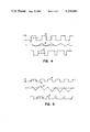
- FIGS. 3-5 are timing charts showing the various control and motor drive signals generated by the elements of the velocity control system described in FIGS. 1 and 2.
- the DC motor 10 is operated by driver circuits 11 connected in well-known manner to the armature of the motor. Details of the driver circuits are not shown since various circuit drivers using transistors are well-known. One such arrangement would utilize PNP and NPN transistors arranged in a bridge configuration which would function to apply current to the armature through various combinations of the transistors in the bridge circuit to control direction as well as speed.
- the drive pulses for energizing the driver circuits 11 for operating motor 10 are obtained from a power source such as comparator 12 whose specific function is to apply voltage pulses of fixed amplitude but of controlled width for drive signal pulses such as shown by curve 77 of FIG. 3.
- the generation of the drive pulses 77 is regulated by a feedback loop which includes optical emitter 13 operatively connected to be driven by the rotation of the drive shaft of motor 10. While an optical emitter is specified, other emitters could be used which operate to produce a uniformly varying timing signal which has a frequency which is proportional the motor velocity. Feedback signals from optical emitter 13 are fed through a divide by N circuit 14 which in effect counts a predetermined number of pulses from optical emitter 13. When the desired number of pulses have been received by circuit 14, an output control pulse signal is applied to single shot 15.
- the standard or reference signal for determining a deviation from a desired velocity is derived directly from the feedback signal without regard to an external reference source and notwithstanding the fact that the feedback signal is also generated at the frequency proportional to the actual velocity of motor 10.
- the output of the divide by N circuit 14 is connected to a monostable circuit device such as single shot 15.
- a pulse from circuit 14 operates to turn ON single shot 15 which then remains ON for a precisely-timed fixed interval which is independent of the frequency of the pulses from emitter 13 and circuit 14.
- the ON time interval of single shot 15 is fixed for each operating cycle of the timing pulses generated by emitter 13 and divide by N circuit 14.
- the OFF time interval of single shot 15 during the period of motor operation is a variable which is dependent on the frequency rate of the timing pulses from circuit 14 and emitter 13.
- ON time interval of the single shot 15 is the fixed reference interval
- the OFF time portion could be fixed and alternatively could be used as the reference interval. Therefore, it will be understood in the description and claims that the term ON time interval includes the converse.
- the ON time interval in accordance with the preferred embodiment for practicing of the invention has a length set at a fixed fraction of the period of the pulses from divide by N circuit 14 when the motor is operated at the desired constant velocity. While the ON time interval of single shot 15 selected can be various, the preferred length is approximately half the period of the pulses from circuit 14 when the motor is operated at the desired constant velocity.
- the output signal from single shot 15 is applied to a switchable current source 16 which is connected at junction 34 with a reference current source 19 to the input of operational amplifier 18 which in conjunction with capacitor 20 form at integrator 17 for the currents I FB and I REF .
- Capacitor 21 and resistor 22 provide a zero-pole for loop compensation which guarantees loop stabilization.
- a voltage signal V 0 from the integrator 17 is applied to a comparator circuit 12 which in turn generates the drive signal curve 77 of FIG. 3.
- a specific circuit design for the motor control of FIG. 1 is shown in FIG. 2.
- Blocks 29 & 30 are connected to provide a reference for the PNP & NPN current sources in order to track equally for power supply variations.
- transistors 31 and 32 make up the switchable current source 16 which when gated on by transistor 33 produces a DC current I FB at junction 34.
- Transistor 33 receives pulses at terminal 35 from single shot 15 (see FIG. 1) of the type shown by curve 69 in FIG. 3.
- Transistor 36 serves as the negative current source 19 which produces the DC current I REF at junction 34.
- Operational amplifier 18 of integrator 17 comprises transistors 37, 38, 39 and 40 connected in the configuration of a Darlington differential amplifier. Transistors 41, 42, 43, 44 and 45 provide the desired biasing current sources. In the preferred embodiment this operational amplifier stage is biased at 10 times that of I REF or I FB so that the offset of the stage is minimized. Diodes 46, 47 and 48 are provided to keep integrator 17 linear and out of saturation or cutoff.
- Transistors 49 and 50 form a differential amplifier front end for the comparator 12 which converts the ripple signal on line 51 from integrator 17 to pulse width modulated drive signals to motor 10 (see FIG. 1) at terminal 56.
- Transistors 52, 53 and 54 serve as current sources to bias comparator 12 and transistor 55 provides the logic output to the motor driver circuits 11 (FIG. 1) at terminal 56.
- Transistors 57 and 58 form a differential amplifier 59 which along with the biasing current sources of transistors 60, 61 and 62 form a motor reset stage.
- reset transistor 63 gates a RESET pulse at terminal 64 to supply current in opposition to I REF .
- the feedback loop is open, for example, by holding the divide by N counter 14 (see FIG. 1) reset which applies a pulse to terminal 35 of gate transistor 33.
- differential amplifier 59 is turned ON by a RESET pulse at terminal 64 to transistor 63.
- Diode 65 permits the motor reset stage to provide current in only one direction into integrator 17 which is equal and opposite to I REF .
- the motor control system operates as follows:
- Emitter 13 connected to the shaft of motor 10 generates feedback timing signals at a frequency which is a function of the actual velocity of the motor. These feedback timing signals are converted by the divide by N circuit 14 to produce a train of binary control pulses 67 as shown in FIG. 3.
- the binary voltage pulses 67 from divide by N circuit 14 are applied to a single shot 15 which is turned on by each leading edge 68 of pulses 67.
- the ON time interval T 1 of pulses 69 from single shot 15 is fixed regardless of the period T of pulses 67.
- This ON time interval T 1 is selected to be a fixed fraction, i.e. approximately one-half of the period of the single shot pulses 69 occurring at the desired motor velocity.
- the period of the train of pulses 69 from single shot 15 is the same as the period of the pulses 67 from the divide by N circuit 14. Since the ON time interval T 1 is fixed, the OFF time interval for single shot 15 will vary dependent on the period T of the pulses from divide by N circuit 14 which are a function of the speed of motor 10.
- Feedback pulses 69 from single shot 15 are applied to the switchable current source 16 to produce analog current control pulses I FB 70.
- T 1 is shown in the preferred embodiment to be approximately 1/2 T, T 1 could be a fraction greater or less than 1/2 T.
- the selection of T 1 is largely a matter of choice determined according to the following expression ##EQU1##
- a practical range for T 1 is represented by the following expression
- the analog current control pulses 70 occur at the same frequency as the binary feedback pulses of single shot 15.
- the current control pulses 70 are positive pulses with an ON time interval T 1 applicable to the input of the integrator 7 at terminal 34 which is also connected to a DC current source 19 which produces a negative I REF 71 of constant value.
- the input control signal to integrator 17 at junction 34 consists of a positive current pulse 72 for time T 1 and a negative pulse 73 for the remainder of the period of single shot 15.
- the current control pulses 72 & 73 occur at a frequency which is a function of the actual velocity of the motor 10; however, the positive ON time T 1 is always fixed and serves as the reference interval which is a function of motor speed at the desired velocity.
- Integrator 17 converts current control pulses 72 and 73 to a ramping output voltage 74 having a positive going ramp 75 when negative current control pulse 73 is ON and a negative going ramp 76 when the positive current control pulse 72 is ON.
- Comparator 12 converts the ramping voltage output 74 from integrator 17 to pulse width modulated drive pulses 77.
- the width T X of the drive pulses 77 produced by comparator 12 is determined by the time between the points of cross-over of ramp 75 and 76 relative to an analog reference voltage, for example, zero volts.
- Comparator 12 converts the output ramping voltage 74 into an output pulse 77 which has a pulse width T X proportional to its average value.
- Curves 78, 79 and 80 of FIG. 4 show the current control pulses, integrator ramp output voltage, and the drive pulses respectively for the increased load condition such that TX varies until the increased load is corrected to the actual desired motor velocity. If the motor speed is too high i.e. the load decreases, feedback current pulses I FB cancel out I REF to a greater degree and the average value of the integrator ramping voltage drops negative thereby decreasing the pulse width T X .
- Curves 81, 82 and 83 in FIG. 5 show the current control pulses, the integrator ramp output voltage and the drive pulses respectively where motor speed increases upon decreased load and is returned to desired speed.
- a motor control system for maintaining a DC motor at a constant velocity which eliminates the need for an independent reference signal source against which signals generated in a feedback system by the operation of the motor is eliminated.
- the feedback signals are themselves converted to a control signal which includes a reference interval of fixed time duration which is the standard or reference for determining changes in the motor velocity and for making the necessary speed corrections to maintain the velocity constant under varying load conditions.
Landscapes
- Engineering & Computer Science (AREA)
- Power Engineering (AREA)
- Control Of Direct Current Motors (AREA)
- Control Of Multiple Motors (AREA)
Priority Applications (6)
| Application Number | Priority Date | Filing Date | Title |
|---|---|---|---|
| US05/961,321 US4218641A (en) | 1978-11-16 | 1978-11-16 | Analog DC motor velocity control loop |
| JP10416979A JPS5568893A (en) | 1978-11-16 | 1979-08-17 | Dc motor speed controller |
| CA000335624A CA1143785A (en) | 1978-11-16 | 1979-09-14 | Analog dc motor velocity control loop |
| FR7926313A FR2441950A1 (fr) | 1978-11-16 | 1979-10-16 | Boucle de commande analogique de la vitesse d'un moteur a courant continu |
| GB7937564A GB2037019B (en) | 1978-11-16 | 1979-10-30 | Systems for controlling the rotational speed of dc motors |
| DE19792945697 DE2945697A1 (de) | 1978-11-16 | 1979-11-13 | Regelungsschaltung zur konstanthaltung der geschwindigkeit eines gleichstrommotors |
Applications Claiming Priority (1)
| Application Number | Priority Date | Filing Date | Title |
|---|---|---|---|
| US05/961,321 US4218641A (en) | 1978-11-16 | 1978-11-16 | Analog DC motor velocity control loop |
Publications (1)
| Publication Number | Publication Date |
|---|---|
| US4218641A true US4218641A (en) | 1980-08-19 |
Family
ID=25504324
Family Applications (1)
| Application Number | Title | Priority Date | Filing Date |
|---|---|---|---|
| US05/961,321 Expired - Lifetime US4218641A (en) | 1978-11-16 | 1978-11-16 | Analog DC motor velocity control loop |
Country Status (6)
| Country | Link |
|---|---|
| US (1) | US4218641A (de) |
| JP (1) | JPS5568893A (de) |
| CA (1) | CA1143785A (de) |
| DE (1) | DE2945697A1 (de) |
| FR (1) | FR2441950A1 (de) |
| GB (1) | GB2037019B (de) |
Cited By (7)
| Publication number | Priority date | Publication date | Assignee | Title |
|---|---|---|---|---|
| US4355268A (en) * | 1980-02-20 | 1982-10-19 | Mobil Oil Corporation | Motor control apparatus |
| US4386302A (en) * | 1979-11-12 | 1983-05-31 | Olympus Optical Co., Ltd. | Control device for a multispeed motor |
| US4422023A (en) * | 1980-07-17 | 1983-12-20 | Olympus Optical Co., Ltd. | Starting circuit for electronically controlled motor apparatus |
| US4516060A (en) * | 1982-11-19 | 1985-05-07 | Nahum Guzik | Digital motor speed control |
| US4638339A (en) * | 1985-11-04 | 1987-01-20 | Kcr Technology, Inc. | Electrographic charge deposition apparatus |
| US4829218A (en) * | 1986-12-18 | 1989-05-09 | Braun Aktiengesellschaft | Direct current adjusting device |
| US5202951A (en) * | 1991-06-05 | 1993-04-13 | Gas Research Institute | Mass flow rate control system and method |
Citations (7)
| Publication number | Priority date | Publication date | Assignee | Title |
|---|---|---|---|---|
| US3241023A (en) * | 1962-03-16 | 1966-03-15 | Fifth Dimension Inc | Motor speed control |
| US3409814A (en) * | 1965-03-17 | 1968-11-05 | Fujitsu Ltd | Variable pulse system for controlling dc motor speed by variation of supplied current |
| US3531704A (en) * | 1965-11-26 | 1970-09-29 | Sony Corp | Speed control system for dc motors |
| US3596162A (en) * | 1968-05-13 | 1971-07-27 | Sony Corp | Speed control system with comparison of a sawtooth wave with a reference level |
| US3740633A (en) * | 1971-03-03 | 1973-06-19 | Honeywell Inf Systems | Frequency-to-voltage converter device |
| US3753067A (en) * | 1972-05-17 | 1973-08-14 | Peripheral Systems Corp | Motor speed regulation system |
| US4024445A (en) * | 1974-07-11 | 1977-05-17 | Nippon Electric Company, Ltd. | Circuit for producing for a feedback motor speed control loop an error signal immune to a change in the source voltage |
Family Cites Families (2)
| Publication number | Priority date | Publication date | Assignee | Title |
|---|---|---|---|---|
| FR1471672A (fr) * | 1965-03-17 | 1967-03-03 | Fujitsu Ltd | Dispositif de réglage de la vitesse |
| JPS5136173U (de) * | 1974-09-10 | 1976-03-17 |
-
1978
- 1978-11-16 US US05/961,321 patent/US4218641A/en not_active Expired - Lifetime
-
1979
- 1979-08-17 JP JP10416979A patent/JPS5568893A/ja active Pending
- 1979-09-14 CA CA000335624A patent/CA1143785A/en not_active Expired
- 1979-10-16 FR FR7926313A patent/FR2441950A1/fr active Granted
- 1979-10-30 GB GB7937564A patent/GB2037019B/en not_active Expired
- 1979-11-13 DE DE19792945697 patent/DE2945697A1/de not_active Withdrawn
Patent Citations (7)
| Publication number | Priority date | Publication date | Assignee | Title |
|---|---|---|---|---|
| US3241023A (en) * | 1962-03-16 | 1966-03-15 | Fifth Dimension Inc | Motor speed control |
| US3409814A (en) * | 1965-03-17 | 1968-11-05 | Fujitsu Ltd | Variable pulse system for controlling dc motor speed by variation of supplied current |
| US3531704A (en) * | 1965-11-26 | 1970-09-29 | Sony Corp | Speed control system for dc motors |
| US3596162A (en) * | 1968-05-13 | 1971-07-27 | Sony Corp | Speed control system with comparison of a sawtooth wave with a reference level |
| US3740633A (en) * | 1971-03-03 | 1973-06-19 | Honeywell Inf Systems | Frequency-to-voltage converter device |
| US3753067A (en) * | 1972-05-17 | 1973-08-14 | Peripheral Systems Corp | Motor speed regulation system |
| US4024445A (en) * | 1974-07-11 | 1977-05-17 | Nippon Electric Company, Ltd. | Circuit for producing for a feedback motor speed control loop an error signal immune to a change in the source voltage |
Cited By (7)
| Publication number | Priority date | Publication date | Assignee | Title |
|---|---|---|---|---|
| US4386302A (en) * | 1979-11-12 | 1983-05-31 | Olympus Optical Co., Ltd. | Control device for a multispeed motor |
| US4355268A (en) * | 1980-02-20 | 1982-10-19 | Mobil Oil Corporation | Motor control apparatus |
| US4422023A (en) * | 1980-07-17 | 1983-12-20 | Olympus Optical Co., Ltd. | Starting circuit for electronically controlled motor apparatus |
| US4516060A (en) * | 1982-11-19 | 1985-05-07 | Nahum Guzik | Digital motor speed control |
| US4638339A (en) * | 1985-11-04 | 1987-01-20 | Kcr Technology, Inc. | Electrographic charge deposition apparatus |
| US4829218A (en) * | 1986-12-18 | 1989-05-09 | Braun Aktiengesellschaft | Direct current adjusting device |
| US5202951A (en) * | 1991-06-05 | 1993-04-13 | Gas Research Institute | Mass flow rate control system and method |
Also Published As
| Publication number | Publication date |
|---|---|
| FR2441950A1 (fr) | 1980-06-13 |
| CA1143785A (en) | 1983-03-29 |
| FR2441950B1 (de) | 1984-06-08 |
| DE2945697A1 (de) | 1980-05-29 |
| GB2037019A (en) | 1980-07-02 |
| GB2037019B (en) | 1983-02-16 |
| JPS5568893A (en) | 1980-05-23 |
Similar Documents
| Publication | Publication Date | Title |
|---|---|---|
| US4468597A (en) | Method for regulating the power supply to a direct-current motor and a device for the application of said method | |
| EP0497432B1 (de) | Apparat zum Betrieb einer Halbleiterlaservorrichtung | |
| US4835780A (en) | Semiconductor laser output control circuit | |
| US4490796A (en) | Print head motor control system using analog and digital feedback | |
| US4460968A (en) | Print head motor control with stop distance compensation | |
| US3989992A (en) | Pulse width modulated control system | |
| US3952236A (en) | Vehicle speed regulation system | |
| US4218641A (en) | Analog DC motor velocity control loop | |
| US4441068A (en) | Bipolar linear current source driver amplifier for switching loads | |
| US3596162A (en) | Speed control system with comparison of a sawtooth wave with a reference level | |
| US4121141A (en) | D.C. motor speed control circuitry | |
| US5703473A (en) | Programmable PWM output voltage independent of supply | |
| US4105935A (en) | Motor speed control apparatus | |
| US4015180A (en) | Speed regulating devices for rotary machines or the like | |
| US3970909A (en) | Constant speed regulator for DC motor | |
| JP2685979B2 (ja) | 電源装置 | |
| US4151448A (en) | Pulse motor driving system | |
| JPS6395886A (ja) | パルス幅変調信号による負荷駆動回路 | |
| EP0051974B1 (de) | Regelschaltung für einen Gleichstrommotor mit Permanentmagnet | |
| JP3060585B2 (ja) | パルス幅変調回路 | |
| KR970031218A (ko) | 토크 하락을 보상하기 위한 전자적으로 정류되는 DC모터용 모터 제어기(Motor controller for electronically commutated DC motors in order to compensate for torque drops) | |
| JPS634434B2 (de) | ||
| JPS567489A (en) | System for controlling photo-output | |
| JPS5927191B2 (ja) | 電動機の速度制御装置 | |
| JPH0121431Y2 (de) |